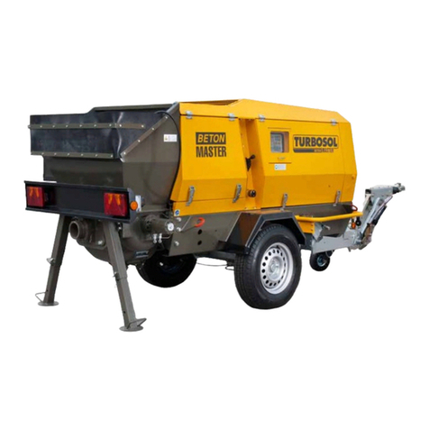
Turbosol BM 30 User manual

Serial number
READ THIS MANUAL CAREFULLY BEFORE USING THE MACHINE.
THIS MANUAL IS AN INTEGRAL PART OF THE MACHINE AND MUST BE KEPT FOR FUTURE REFERENCE
UNTIL THE MACHINE IS DISPOSED OF
USE AND MAINTENANCE MANUAL
BM 30
IS13/02 - 561291
EN IT
ORIGINALI

THIS MANUAL IS PROPERTY OF - ANY TOTAL OR PARTIAL REPRODUCTION IS STRICTLY FORBIDDEN

INDEX
THIS MANUAL IS PROPERTY OF - ANY TOTAL OR PARTIAL REPRODUCTION IS STRICTLY FORBIDDEN
1 CE DECLARATION .................................................................................................................................................1
1.1 CE DECLARATION OF CONFORMITY...........................................................................................................1
2 GENERAL INFORMATION......................................................................................................................................1
2.1 IMPORTANCE OF THE MANUAL....................................................................................................................1
2.2 ABBREVIATIONS ............................................................................................................................................1
2.3 NOTES.............................................................................................................................................................1
2.4 DESCRIPTION OF THE SYMBOLS.................................................................................................................1
2.5 "MACHINE OFF" STATE..................................................................................................................................1
2.6 MAIN INFORMATION AND CONTACTS .........................................................................................................2
3 TECHNICAL DESCRIPTION...................................................................................................................................1
3.1 MACHINE NAME..............................................................................................................................................1
3.2 MACHINE DIMENSIONS.................................................................................................................................2
3.3 TECHNICAL DATA ..........................................................................................................................................2
3.4 DESTINATION OF USE...................................................................................................................................2
3.5 PRODUCTS USED FOR PROCESSING.........................................................................................................2
3.6 NAME OF COMPONENTS...............................................................................................................................3
4 TRANSPORT AND HANDLING...............................................................................................................................1
4.1 MACHINE TRANSPORT AS ROAD TRAILER.................................................................................................1
4.2 LIFTING ...........................................................................................................................................................3
5 INSTALLATION.......................................................................................................................................................1
5.1 PLACEMENT ...................................................................................................................................................1
5.2 PIPING.............................................................................................................................................................1
5.2.1 Piping line layout...........................................................................................................................................2
- Horizontal pumping..............................................................................................................................................2
- Vertical pumping..................................................................................................................................................2
- Downward pumping .............................................................................................................................................2
5.3 CONCRETE PIPING FITTINGS.......................................................................................................................3
5.4 CONNECTIONS...............................................................................................................................................3
5.4.1 Remote control..............................................................................................................................................3
5.4.2 Radio control \(optional\)...............................................................................................................................4
6 SAFETY...................................................................................................................................................................1
6.1 MAIN RULES ...................................................................................................................................................1
6.1.1 Correct use....................................................................................................................................................1
6.1.2 Incorrect use .................................................................................................................................................1
6.1.3 Emergency stop............................................................................................................................................1
6.1.4 Emergency button re-arm .............................................................................................................................2
6.2 SAFETY DEVICES...........................................................................................................................................3
6.3 SAFETY SIGNALS...........................................................................................................................................4
6.4 PERSONAL PROTECTIVE EQUIPMENT........................................................................................................6

INDEX
THIS MANUAL IS PROPERTY OF - ANY TOTAL OR PARTIAL REPRODUCTION IS STRICTLY FORBIDDEN
6.5 RESIDUE RISKS..............................................................................................................................................6
7 USE AND OPERATION...........................................................................................................................................1
7.1 OPERATION PRINCIPLE ................................................................................................................................1
7.2 PUMPABLE MATERIALS.................................................................................................................................1
7.3 CHECKS BEFORE SWITCH-ON.....................................................................................................................2
7.4 CONTROLS .....................................................................................................................................................4
7.5 MACHINE SWITCH-ON...................................................................................................................................6
7.6 Additive pump parameters settings..................................................................................................................7
7.7 CLEANING AT END OF WORK.....................................................................................................................10
7.7.1 Cleaning the machine .................................................................................................................................10
7.7.2 Using the high pressure water jet machine.................................................................................................10
7.7.3 Cleaning the pipes ......................................................................................................................................11
- Cleaning with water............................................................................................................................................12
- Water-suction cleaning......................................................................................................................................12
7.8 IMPORTANT WARNINGS .............................................................................................................................12
8 MAINTENANCE.......................................................................................................................................................1
8.1 MAIN WARNINGS ...........................................................................................................................................1
8.1.1 Environmental protection ..............................................................................................................................1
8.1.2 Maintenance instructions ..............................................................................................................................1
8.2 OPERATOR RESPONSIBILITY.......................................................................................................................2
8.2.1 Replacing lubrication water...........................................................................................................................2
8.2.2 Engine cooling liquid check...........................................................................................................................2
8.2.3 Engine oil check............................................................................................................................................2
8.2.4 Engine air filter check....................................................................................................................................3
8.2.5 Diesel oil level check.....................................................................................................................................3
8.2.6 Hydraulic oil level check................................................................................................................................3
8.2.7 At end of work...............................................................................................................................................4
8.3 PUMPING PISTONS REPLACEMENT............................................................................................................4
8.4 S VALVE ADJUSTMENT .................................................................................................................................7
8.5 WEAR PLATE, WEAR DISC REPLACEMENT................................................................................................8
8.6 I OIL FILTER REPLACEMENT ........................................................................................................................9
8.7 II OIL FILTER REPLACEMENT .....................................................................................................................10
8.8 Replacing the additive metering pump...........................................................................................................11
8.8.1 Greasing dosing pump................................................................................................................................11
8.9 ROAD TOW MAINTENANCE.........................................................................................................................12
8.10 ENABLED PERSONNEL RESPONSIBILITY...............................................................................................14
8.10.1 Maintenance coupon at 50 hours..............................................................................................................14
8.10.2 Monthly check or every 125 hours ............................................................................................................14
8.10.3 Check every 250 hours.............................................................................................................................15
8.10.4 Six-monthly check or every 500 hours......................................................................................................15
8.10.5 Annually check or every 1000 hours.........................................................................................................15
8.10.6 Check every 2500 hours...........................................................................................................................15

INDEX
THIS MANUAL IS PROPERTY OF - ANY TOTAL OR PARTIAL REPRODUCTION IS STRICTLY FORBIDDEN
9 DEMOLITION...........................................................................................................................................................1
9.1 MAIN WARNINGS ...........................................................................................................................................1
10 TROUBLESHOOTING.............................................................................................................................................1
10.1 FAULTY ELECTRONIC BOARD....................................................................................................................1
10.2 PUMPING SYNCHRONISM RESET..............................................................................................................1
10.3 OPERATOR INTERVENTION........................................................................................................................2
11 OPERATOR RESPONSIBILITY ..............................................................................................................................1
11.1 RESPONSIBILITY..........................................................................................................................................1
11.2 WARRANTY...................................................................................................................................................1

EN BM 30 IS13/02 - 561291 1 - CE DECLARATION
Cap. 1 - Pag. 1/1
THIS MANUAL IS PROPERTY OF - ANY TOTAL OR PARTIAL REPRODUCTION IS STRICTLY FORBIDDEN
1.1 CE DECLARATION OF CONFORMITY
The original CE Declaration of conformity is provided separately from the manual.

EN BM 30 IS13/02 - 561291 2 - GENERAL INFORMATION
Cap. 2 - Pag. 1/2
THIS MANUAL IS PROPERTY OF - ANY TOTAL OR PARTIAL REPRODUCTION IS STRICTLY FORBIDDEN
2.1 IMPORTANCE OF THE MANUAL
This "Use and maintenance instructions" technical manual is drawn up as indicated in the European Directives, in
order to guarantee an easy and correct understanding of the subject therein by the operators authorised to use and
service the machine in question. In the event the operators do not understand this manual, despite the manufacturer's
efforts during its drawing up, please immediately request clarifications and further information from the manufacturer,
to avoid personal interpretations that might jeopardise safety. The authorised operators must read and undersanding
this "Use and maintenance instructions" technical manual and strictly comply with the standards therein before using
the machine in question, in order to guarantee their and others safety, obtain the best machine performances and
assure maximum efficiency and duration of its components. This manual must be available to the authorised
operators at any moment and be well kept and preserved near the machine.
The machine's use and maintenance are the sole duty of the trained and enabled personnel.
The accident-prevention instructions and current rules (in own country/state) on safety at work must be respected. The
manufacturer is not liable for any damages due to arbitrarily made changes and/or tampering with the machine. We
recommend making a note of the machine's serial number that must always be provided whenever requesting assistance or
spare parts, to facilitate the work of personnel in charge. This manual reflects the state of the art at time of marketing the
machine and cannot be considered inadequate because subsequently updated due to newly acquired experience.
Any reprint or reproduction, even partial, of this manual must be authorised by us in writing.
THE MANUFACTURER DECLINES EVERY LIABILITY FOR INJURIES TO PERSONS, DAMAGES TO ANIMALS OR
PROPERTY DUE TO THE NON-COMPLIANCE WITH THESE STANDARDS AND WARNINGS.
2.2 ABBREVIATIONS
ca. around min minutes
cap. chapter N. number
DPI device of individual protection pag. page
DX right par. paragraph
h times pos. position
EN European Norm RIF. reference
Es. example s second
FIG. figure SX left
max. maximum TAB. table
min. minimum v. see
TAB.01
2.3 NOTES
Bold:
Highlights significant phrases in the text.
2.4 DESCRIPTION OF THE SYMBOLS
The following symbols will be used in the manual to highlight particularly important indications and warnings:
ATTENTION: this symbol indicates the operator's accident-prevention standards.
PRECAUTION: this symbol indicates the possibility of damaging the machine and/or its components.
DANGER: this symbol indicates the presence of electric energy.
IMPORTANT NOTE: this symbol provides useful information.
2.5 "MACHINE OFF" STATE
The motor must be switched off using the ON/OFF button before performing any maintenance and/or adjustment operation.

EN BM 30 IS13/02 - 561291 2 - GENERAL INFORMATION
2- Pag. 2/2
THIS MANUAL IS PROPERTY OF - ANY TOTAL OR PARTIAL REPRODUCTION IS STRICTLY FORBIDDEN
Cap.
2.6 MAIN INFORMATION AND CONTACTS
The BM 30 concrete pump can be supplied with different accessories. Therefore, not all components described in this manual
are necessarily assembled on your machine.
Turbosol Produzione S.p.A. customer service is at your complete disposal for any further information.
Turbosol Produzione S.p.A.
Via Volta, 1
31030 Pero di Breda di Piave (TV) - ITALIA
Tel. +39 - 0422 - 90.2.51
Fax +39 - 0422 - 90.44.08
website: www.turbosol.it
e-mail: [email protected]
THE TURBOSOL MACHINES
Are the result of years of experience and continuous development. The "know-how" in this way acquired constitutes an
essential guarantee, together with the high level of attention to quality, for the manufacture of long-lasting, greatly reliable
machines and handling costs reduction.
MAINTENANCE AND CARE
Maintenance and care are significantly important for the machine's operation to correspond to expectations. Therefore, in order
to maintain the warranty valid, it is essential to respect the prescribed maintenance intervals and accurately perform the
necessary maintenance.
SAFETY
Service personnel must also be informed on the safety standards The general standards on safety and accident-prevention
foreseen by local legislation, must also be observed.
TRAINING
The operator must be specifically trained to correctly execute the operation.
TURBOSOL SERVICE
Contact the Turbosol dealer for any machine problem or need for spare parts.

EN BM 30 IS13/02 - 561291 3 - TECHNICAL DESCRIPTION
Cap. 3 - Pag. 1/3
THIS MANUAL IS PROPERTY OF - ANY TOTAL OR PARTIAL REPRODUCTION IS STRICTLY FORBIDDEN
3.1 MACHINE NAME
Manufacturer plate
123
kg k
FIG.01
The series (1), the machine model (2) and the machine's serial number (3) and the power data are engraved on the plate.
Below is the meaning of the used symbols.
(1) = Machine series.
(2) = Machine model.
(3) = Machine's serial number.
/T = With road approved tow.
Manufacturer plate position
As the figure shows, the manufacturer plate (FIG.02-REF.1) is fixed to the base of the machine.
Machine's serail number and road tow plate position
The machine's serial number (FIG.02-REF.2) is punched on the machine's base and on the manufacturer's plate.
The vehicle's identification number (FIG.02-REF.3) is punched and an approval identification data plate (FIG.02-REF.4) is
present in the versions fitted with road approved tow.
1
2
3
4
FIG.02

EN BM 30 IS13/02 - 561291 3 - TECHNICAL DESCRIPTION
3- Pag. 2/3
THIS MANUAL IS PROPERTY OF - ANY TOTAL OR PARTIAL REPRODUCTION IS STRICTLY FORBIDDEN
Cap.
3.2 MACHINE DIMENSIONS
We give the machine's maximum dimensinos and gross weight (ready to operate).
BM 30 D/T
LENGTH WIDTH HEIGHT WEIGHT*
4820
mm
1610
mm
1660
mm
2100
kg
TAB.03
*Weight with full diesel oil and hydraulic oil tank, without optional components.
3.3 TECHNICAL DATA
Fow rate* m3/h 30
Maximum pressure on concrete bar 80
Maximum number of cycles per minute - 26
Pumping cylinders (diameter x run) mm 180 x 700
Installed power kW 37.3
Electric control system power supply V 12 AC
Main hydraulic circuit maximum pressure bar 320
Auxiliary hydraulic circuit maximum pressure bar 180
Maximum pumping granulometry** mm 25÷30
Maximum serviced distance*** m 150÷200
Maximum serviced height*** m 100÷120
Delivery manifold inches 5.5
Hopper capacity litres 300
Diesel oil tank capacity litres 40
Oil tank capacity (hydraulic system) litres 75
Hydraulic oil (recommended) TOTAL AZOLLA HZS 46
Maximum height A.S.L. of installation place without sensitive power loss m 1000
Admitted environmental temperature °C -
Sound power level Lw dB 104
Equivalent continuous A Lp-weighted sound pressure level dB 92
Endothermic engine: PERKINS 404D-22
Power kW 37.3
minimum 1550
Engine rpm maximum (vacuum) rpm 2900
Engine oil (recommended) TOTAL RUBIA TDI 15W40
TAB.04
* Theoretical.
** Maximum granulometry 30 mm if aggregate obtained for crushing, maximum granulometry 35 mm if spheroidal aggregate.
*** Maximum values not simultaneously obtainable.
3.4 DESTINATION OF USE
The machine is designed and manufactured for the following use destination:
FIELD OF USE: building sector
INTENDED USE: pumping of concrete and spritzbeton.
3.5 PRODUCTS USED FOR PROCESSING
- Concrete with maximum granulometry of 30 mm if aggregate obtained for crushing, maximum granulometry of 35 mm if
spheroidal aggregate.
- Spritzbeton (shotcrete).

EN BM 30 IS13/02 - 561291 3 - TECHNICAL DESCRIPTION
Cap. 3 - Pag. 3/3
THIS MANUAL IS PROPERTY OF - ANY TOTAL OR PARTIAL REPRODUCTION IS STRICTLY FORBIDDEN
3.6 NAME OF COMPONENTS
1
3
2
7
4
6
811
12
13 14
15 16
17
18
9
10
FIG.03
The road tow is shown in the figure.
KEY
FIG.03-REF.1 - Bodywork
FIG.03-REF.2 - Upper hopper
FIG.03-REF.3 - Grid
FIG.03-REF.4 - Vibrator
FIG.03-REF.6 - Control board
FIG.03-REF.7 - Tow
FIG.03-REF.8 - Exchanger
FIG.03-REF.9 - Engine
FIG.03-REF.10 - Hydraulic pump unit
FIG.03-REF.11 - Mixer
FIG.03-REF.12 - Lower hopper
FIG.03-REF.13 - Delivery flange
FIG.03-REF.14 - S Valve
FIG.03-REF.15 - S Valve exchange jack
FIG.03-REF.16 - Pumping barrel
FIG.03-REF.17 - Water tank
FIG.03-REF.18 - Hydraulic pumping cylinder

EN BM 30 IS13/02 - 561291 4 - TRANSPORT AND HANDLING
Cap. 4 - Pag. 1/3
THIS MANUAL IS PROPERTY OF - ANY TOTAL OR PARTIAL REPRODUCTION IS STRICTLY FORBIDDEN
4.1 MACHINE TRANSPORT AS ROAD TRAILER
Only machines fitted with frame in road towing version can travel on public roads.
Respect the highway code when towing the machine.
The machine cannot be used for transporting any load, not even the accessories foreseen for machine
operation (piping, fittings, gaskets, etc.).
Obligations before towing the machine
- Check the diesel engine is off.
- Remove all connected piping from machine (e.g.: concrete pipes, additive pipe).
- Close and block the mobile bodywork checking the hooks are properly closed.
- After having lowered the wheel lift the parking feet to support the machine weight (FIG.04).
- Correctly assemble and fix the lighting bar. Connect and check correct operation of the lighting bar cable.
- Introduce the pull cable in the appropriate cable guide eyelet (FIG.06 and FIG.07).
- Remove the wheels' parking wedges and place them in their housing.
- Release the wheels' parking brake.
Safety prescriptions
- Adjust the drawbar's height only using the handle (FIG.05-REF.03).
- Pull the trailer's parking brake during parking or stop.
- Fix the trailer with two wedges after having released it.
Repulsion brake adjustment
- Remove the split pin (FIG.05-REF.01).
- Loosen the handle (FIG.05-REF.02) and turn it until it stops.
- Adjust the coupling element upwards (50°) or downwards (10°) by means of the repulsion brake handle until it stops.
- Fasten and fix the handle hitting it with a mallet (hard rubber mallet). Insert the split pin.
- Fasten the handle again after about 50 km.
Parking
Pull the hand brake: forcely fasten the hand brake beyond the dead centre.
In start
Loosen the hand brake: place the hand brake lever back to initial position. The dead centre is easily detectable.
The side parts of the towing bar may loosen if not used for a prolonged period of time, due to sudden side or
upward movements.
Pay attention and check the cable is sufficiently long for journeys with bends. An excessively extended cable
may accidentally activate the brake. House the cable around the towing hook's stem if without appropriate drive
eyelet, and hook the snap hook on the cable itself (FIG.07). The cable activates the parking brake (emergency
brake) should the trailer accidentally detach from the drive. The cable must be correctly introduced inside the
cable guide ring to guarantee excellent emergency brake operation.

EN BM 30 IS13/02 - 561291 4 - TRANSPORT AND HANDLING
4- Pag. 2/3
THIS MANUAL IS PROPERTY OF - ANY TOTAL OR PARTIAL REPRODUCTION IS STRICTLY FORBIDDEN
Cap.
4
2
5
1
3
FIG.04 FIG.05
FIG.06 FIG.07
Releasing the machine from the towing vehicle
- Lower and block the wheel.
- Activate the parking brake.
- Release the machine from the towing vehicle.
Always block the machine using the parking brake and supplied wedges to avoid any movement when releasing
the machine on a slope.
BM 30 can be transported on motor gearbox vehicles; the machine's load, arrangement and transport on a
vehicle must respect the current highway code. If having to load BM 30 onto the vehicle using listing means,
consult paragraph 4.2 LIFTING.

EN BM 30 IS13/02 - 561291 4 - TRANSPORT AND HANDLING
Cap. 4 - Pag. 3/3
THIS MANUAL IS PROPERTY OF - ANY TOTAL OR PARTIAL REPRODUCTION IS STRICTLY FORBIDDEN
4.2 LIFTING
The machine has four lifting points and a lifting beam (FIG.08).
Hook the ropes to the lifting beam (FIG.08-REF.1) and to the four lifting points, ensuring to connect the shortest ropes to hooks
(FIG.08-REF.2) and the longer ones to hooks (FIG.08-REF.3).
Use the lifting beam to lift BM 30 only.
Do not use the lifting beam to lift any other load.
Check the lifting beam's integrity before using it, and replace it if required.
1
2
3
FIG.08
Lifting must happen fully respecting all lifting standards in force, equally the used means must be conform with
current standards and perfectly preserved. Personnel in charge of the lifting mean must be adequately trained
and enabled for its use.
Use approved hooks and ropes for lifting 2,000 kg.
Ensure no one is too close to the machine before lifting it.
Do not stand underneath the suspended load.
Avoid damaging the components by not lifting or lowering the machine with sudden movements.
Do not alter the connection point for the lifting hook.
Move the machine on flat surfaces only, avoid any slope to prevent danger of running over or crushing between
machine and fixed obstacles.

EN BM 30 IS13/02 - 561291 5 - INSTALLATION
Cap. 5 - Pag. 1/4
THIS MANUAL IS PROPERTY OF - ANY TOTAL OR PARTIAL REPRODUCTION IS STRICTLY FORBIDDEN
5.1 PLACEMENT
Place the machine horizontally; the maximum admitted longitudinal and transversal slope is 5° (FIG.09).
140 cm 140 cm
120 cm
120 cm
FIG.09 FIG.10
- Place the machine in the most suitable point on site for best use of the piping's action range.
- Brake the machine and block the wheels using appropriate parking wedges.
- Ensure the machine rests on the side stabilising feet.
Clear passages (FIG.10) from any encumbrance and a floor surface without holes or dangerous projections must
be present around the machine.
Do not use the wheel as support during work: the machine must rest on the side stabilising feet and the
wheels, and this position must be stable.
5.2 PIPING
Lay piping limiting their length as much as possible (transport and wear times are reduced), checking it is in good condition.
Use flexible rubber hoses only in the last piping section and with length of not more than 4 m; the use of
rubber hoses in other position along the piping, jeopardises pumping (water separation from concrete) and
increases risk of clogging.
Use only TURBOSOL PRODUZIONE S.p.A. original piping and fittings or those from companies expressly
authorised by them. TURBOSOL PRODUZIONE S.p.A. will not, in any event, answer for any injuries to people or
damages to property
determined by the use of non-original piping or fittings.
Ensure the internal surface of the used flexible hose end is not torn or deteriorated, before pumping. Deforming
of the internal surface may cause dangerous cloggings.

EN BM 30 IS13/02 - 561291 5 - INSTALLATION
5- Pag. 2/4
THIS MANUAL IS PROPERTY OF - ANY TOTAL OR PARTIAL REPRODUCTION IS STRICTLY FORBIDDEN
Cap.
5.2.1 Piping line layout
BM 30 can pump horizontally, upwards and downwards. Below are some general rules for the different types of layouts.
1
FIG.11 FIG.12
- Horizontal pumping
Lay piping as wanted and connect it to the first section shown in FIG.11 to pump material horizontally.
- Vertical pumping
The vertical piping section must be fixed and supported using the appropriate collars (FIG.12-REF.1).
- Downward pumping
The downward piping section must be fixed and supported using the appropriate collars (FIG.13-REF.1).
Arrangements must be made to stop the concrete fall in the downward section (e.g. assemble a bend or S-bend - as in FIG.13
or make tilted sections). For this type of layout, we recommend lubricating pipes with grout as follows:
- introduce two wash sponges in the piping's initial section (FIG.14).
- Pump the grout. The entire internal surface of the downward section will, in this way, be lubricated. Introduce more sponges
and more grout if the downward section is particularly long.
1
2
BOIACCA
SPUGNE
DI LAVAGGIO
FIG.13 FIG.14

EN BM 30 IS13/02 - 561291 5 - INSTALLATION
Cap. 5 - Pag. 3/4
THIS MANUAL IS PROPERTY OF - ANY TOTAL OR PARTIAL REPRODUCTION IS STRICTLY FORBIDDEN
5.3 CONCRETE PIPING FITTINGS
Check fittings are always effective and clean.
Check the rubber gasket (FIG.15-REF.1) is present and fully fasten the levers (FIG.15-REF.2) when connecting the piping
segments.
1
2
FIG.15
5.4 CONNECTIONS
- Connect the electric vibrator's plug (FIG.16-REF.1) to th emachine socket (FIG.16-REF.2) located on the hydraulic tank.
Close the door after connection.
1
2
3
FIG.16
5.4.1 Remote control
The machine is given a remote control via cable;
- Insert the plug (FIG.17-REF.1) in the connector's socket (FIG.17-REF.2) located on the machine's bodywork.
- Activate the mortar pump by placing the selector switch (FIG.17-REF.3) at 1, at 0 to stop pumping and at 2 to reverse rotation
direction.

EN BM 30 IS13/02 - 561291 5 - INSTALLATION
5- Pag. 4/4
THIS MANUAL IS PROPERTY OF - ANY TOTAL OR PARTIAL REPRODUCTION IS STRICTLY FORBIDDEN
Cap.
1
2
3
FIG.17
5.4.2 Radio control (optional)
- Connect the plug (FIG.18-REF.1) to the connector's socket (FIG.18-REF.2).
- Use the button (FIG.18-REF.3) to switch the transmitter on and off.
- Start pumping by pressing the button (FIG.18-REF.4); press again to stop pumping.
- Reverse pumping (mix intake from hopper piping) with button (FIG.18-REF.4) at ON, press the button (FIG.18-REF.5) for as
long as required.
24
5
3
1
FIG.18

EN BM 30 IS13/02 - 561291 6 - SAFETY
Cap. 6 - Pag. 1/6
THIS MANUAL IS PROPERTY OF - ANY TOTAL OR PARTIAL REPRODUCTION IS STRICTLY FORBIDDEN
6.1 MAIN RULES
The machine was designed and built to satisfy the essential safety requirements under the CE certificate standards.
The manufacturer has taken all necessary measures to eliminate most of the dangers related to the machine's use conditions,
both foreseen and reasonably predictable.
The manufacturer recommend carefully following this Manual's instructions, procedures and recommendations to safely use
the machine, and also recommends complying with the current safety at work legislation.
Only qualified and purposely trained personnel can use the machine.
Only use the machine in perfect conditions, conform with its destination. Observe the safety and prevention
standards. Comply with this use and maintenance manual dispositions.
The operator must request, know and apply all safety prescriptions applicable to the work environment.
The operator must follow this Use and maintenance manual instructions.
The manual must always be carefully kept on the machine. Immediately request a copy from TURBOSOL
PRODUZIONE SPA or your dealer, if no longer legible.
The operator must be in perfect physical and psychological conditions to perform his work. The operator must
not be occasional, but have gained experience with the machine.
It is forbidden to use the machine to convey loads.
It is forbidden to use the machine for lifting loads and/or persons.
6.1.1 Correct use
The machine is designed for transporting concrete. Machine use is limited to the work place where pumping occurs. Maximum
pressure must not exceed the technical data limit in this manual. Correct use also means respecting this manual's instructions.
6.1.2 Incorrect use
Incorrect use means all that is not intended as correct use. TURBOSOL declines every responsibility for damages caused by
incorrectly using the machine and considers the machine's warranty void.
6.1.3 Emergency stop
The emergency button is the red mushroom-shaped button located on the control column (FIG.19-REF.1).
The emergency system must be used to protect the operator's safety and that of persons near the danger area or the machine
itself, when the normal stop procedure requires an excessively long time.

EN BM 30 IS13/02 - 561291 6 - SAFETY
6- Pag. 2/6
THIS MANUAL IS PROPERTY OF - ANY TOTAL OR PARTIAL REPRODUCTION IS STRICTLY FORBIDDEN
Cap.
1
FIG.19
6.1.4 Emergency button re-arm
Remove the causes that have entailed using the device, before re-activating the machine from the emergency
condition.
The emergency conditions remains such until re-arm, to avoid accidental re-start.
Proceed as follows to re-arm:
- Turn the red "button" in the direction of the engraved arrows.
- The button re-arms and the machine is ready for start procedure.
Table of contents
Other Turbosol Construction Equipment manuals

Turbosol
Turbosol GIOTTO MONO User manual

Turbosol
Turbosol UNI 30 E User manual

Turbosol
Turbosol GIOTTO User manual

Turbosol
Turbosol MINI AVANT User manual

Turbosol
Turbosol TSR 7 User manual

Turbosol
Turbosol Beton Master User manual

Turbosol
Turbosol Beton Master User manual

Turbosol
Turbosol PRO H CL Specification sheet

Turbosol
Turbosol POLI T Specification sheet