Apex Digital SGS User manual

Solar Geyser System (SGS)
TECHNICAL MANUAL
Document Number: SGSP100
20 February 2023

2Solar Geyser System Manual
1.1 Contents Of The Box
1.2 Device Documentation
1.3 About This Manual
1. Introduction
3.1 Symbols
3.2 Purpose
3.3 Transport Damage Check
3.5 Special Hazards
3.6 Installation Place
3.7 Alterations
3.8 Cleaning And Maintenance
3.9 General Hazards Resulting From
Non-Compliance With Safety Standards
3.10 General Safety Requirements
3.11 Local Requirements
3.12 Other Considerations
4.1 Overview And Description
4.2 Electrical Interfaces
5.1 Safety
5.2 Installation Of The SGS
5.3 Electrical Installation
5.4 Powering Up The SGS
6.1 Commissioning
6.2 Operating Modes
6.4 LED Status Indicators
6.5 Fault Finding
6.6 Other Errors
6.7 Service, Support And Repairs
6.8 Warranty
7.1 App Introduction
7.2 Connectivity
7.3 Installer’s Remote Monitoring
7.4 User’s Remote Monitoring
2. Technical Specifications
3. Safety Instructions
4. Device Description
5. Installation
6. Operation
7. Mobile Applications & Wi-Fi Connectivity
8. Contact Us
Table of contents
03
03
03
03
04
06
06
06
06
06
07
07
07
07
07
07
07
06
08
08
08
08
09
09
09
11
09
12
12
12
13
13
14
14
14
12
15
15
16
17
15
18
Solar Geyser System Manual 3
Inside the box you should nd:
• 1 x Apex SGS system
• 1 x mounting bracket
• 1 x securing screw
• 1 x temperature probe
• 1 x pair MC4 connectors
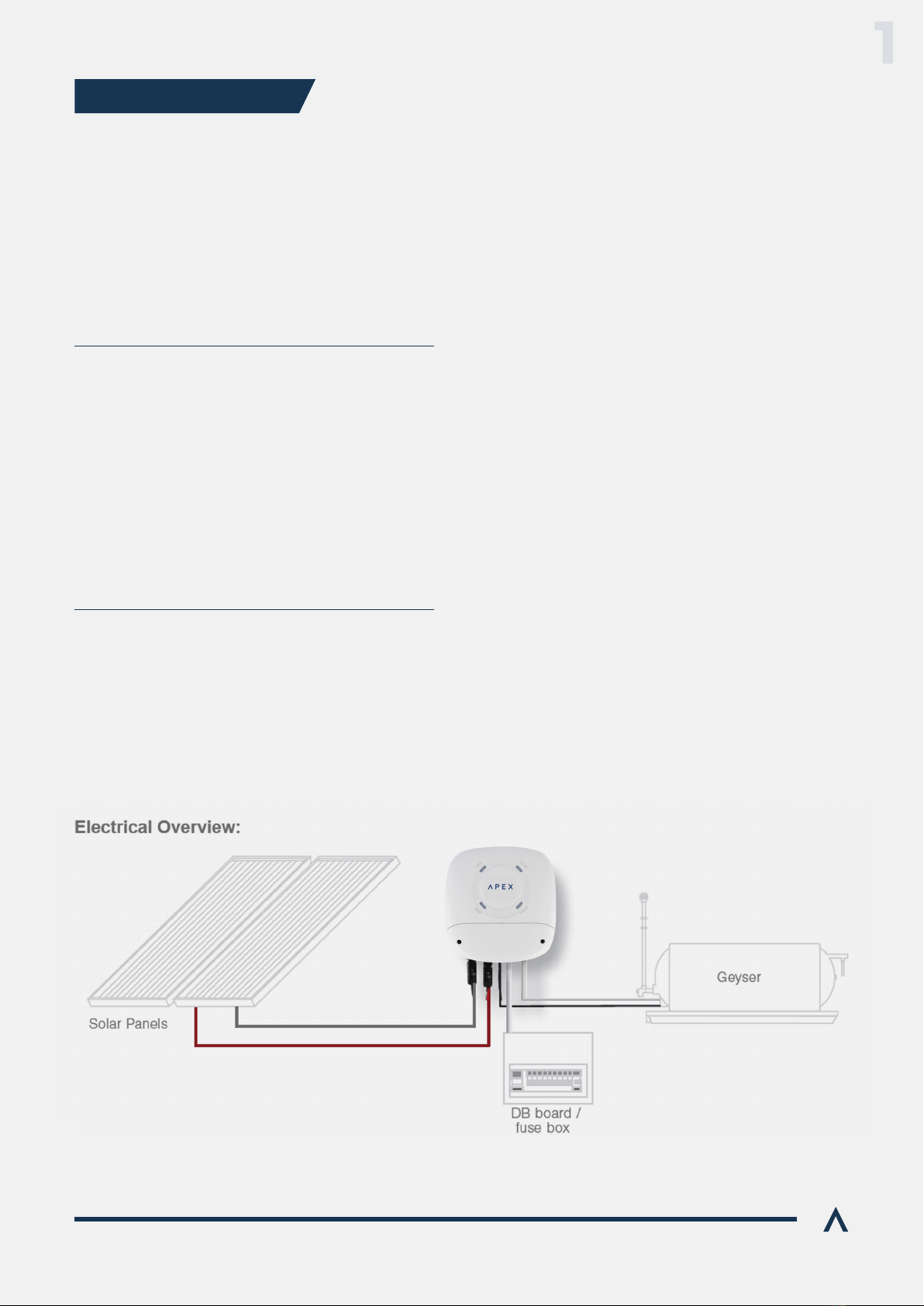
The Apex SGS is the heart of a water heating system –
intelligently heating water in a standard electric geyser
from the sun’s energy. The SGS controls and manages
the system, providing historical and up to the minute
information on status and performance via its web app.
Through considering factors beyond just temperature,
the system makes intelligent decisions – ensuring that
minimal grid power is used. When both grid and solar
power sources are available, the system favours solar
as its power source, ensuring maximum savings.
Figure 1, below, shows a typical installation.
• Monitor and control your Apex SGS on any
compatible browser
• Fully customizable according to your hot water needs.
Apex SGS documentation includes this manual and its
datasheet sheet.
All latest version documents can be downloaded from
www.ApexSolar.Tech.
This manual describes the correct use and features of
the Apex SGS. It includes technical data as well as user
about its correct functioning.
This document is subject to regular updates.
The contents of this manual might change partially or
completely, and it is the responsibility of the user to make
sure that they are using the latest version which is
available at www.ApexSolar.Tech.
Apex reserves the right to modify the manual without
prior notice.
1.1 CONTENTS OF THE BOX
1.2 DEVICE DOCUMENTATION
1.3 ABOUT THIS MANUAL
Figure 1. SGS PV geyser system overview
Optimise your hot water generation with the
latest technology.
1. INTRODUCTION
1
4
Solar Geyser System
Solar Geyser System Manual
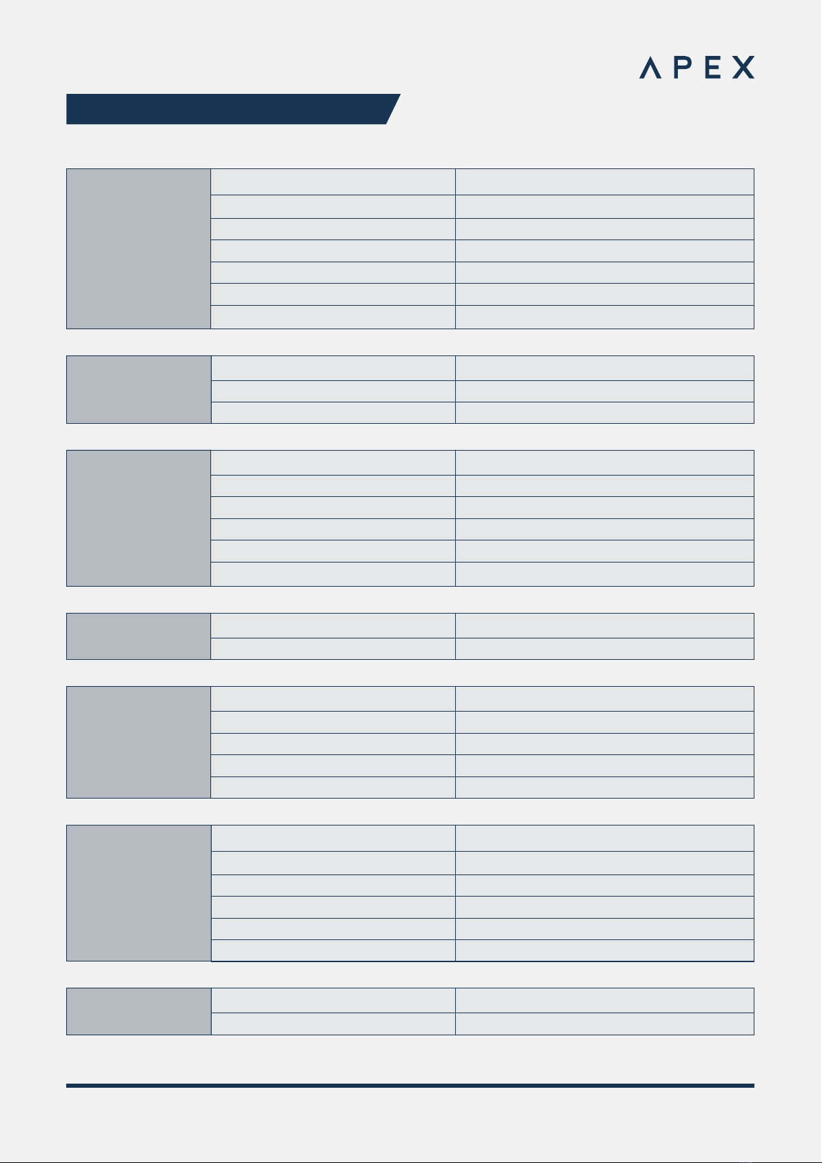
ELECTRICAL SPECIFICATIONS:
AC Input:
Description Specication
Voltage
Frequency
Current
Connection
Installation Pre-requisites
AC Detection
230V AC
50 Hz
15A
3 x 4mm2Screw Terminals
Yes
Voltage
Frequency
Current
230V AC
50 Hz
15A
AC Mode Output:
Solar Input:
Input Voltage Range
Maximum Input Current
Maximum Power Input
MPPT Range
Connection
Installation Pre-requisites
110 - 230VDC
15A
1500W
125 - 230VDC
MC4 Solar Connectors
External AC and PV Isolators
Solar Mode Output: Voltage
Max Current
40-230Vrms Modulated DC
15A
Description Specication
Temperature Sensor:
Measurement Range
Accuracy
Type
Cable Length
Connector
10°C to 85°C
+-2°C
10m
Communications: Wi-Fi
802.11 b/g/n
Geyser Element:
Max Voltage
Power
Element Resistance
Connection at Device
Connection at Element
230V
2000W - 3000W
17Ω– 27Ω
3 x 4mm2 Screw Terminals
2 + Earth
2. TECHNICAL SPECIFICATIONS

5
Solar Geyser System
Solar Geyser System Manual
Mechanical
specications:
Description Specication
Cooling
Cable Strain Relief
Ingress Protection
Terminal Access
210mm x 225mm x 84mm
Natural Convection
Integrated for AC cables and thermal probe
IP2X
Removable cover
Installation
specications:
Mounting
Environment
Fasteners
Vertical only
Indoor Use only. Not for in-roof installation.
Wall plugs with pozi screws
Environmental
Conditions:
Maximum Ambient Temperature
Relative Humidity
Operating Altitude
0°C to +30°C full output, limited output up to +50°C
0 % - 80%
0…..2000m
Device safety
features:
Device Over-Temperature Shutdown
Over Current Protection
Solar Reverse Polarity Protection
Grid feedback safety
75°C
No
Relay based power path management
Certication and
compliance:
RF
EMC
ICASA
NRCS
Safety
EN 300-328, Designed to IEC 60730
EN 301489-1, Designed to IEC 60730
RF approved
RCC 2112093
IEC 60950-1 Electrical Safety
IEC 60730-1 Automated electrical controls
User safety features: Earth Leakage detection Residual Current Detection
User Interface:
On Device
Remote
RGB Digital LED x 4 + local access point
Web browser
Solar Geyser System Manual 6
Please read and follow all the below safety instructions and precautions before installation and use
of the Apex SGS.
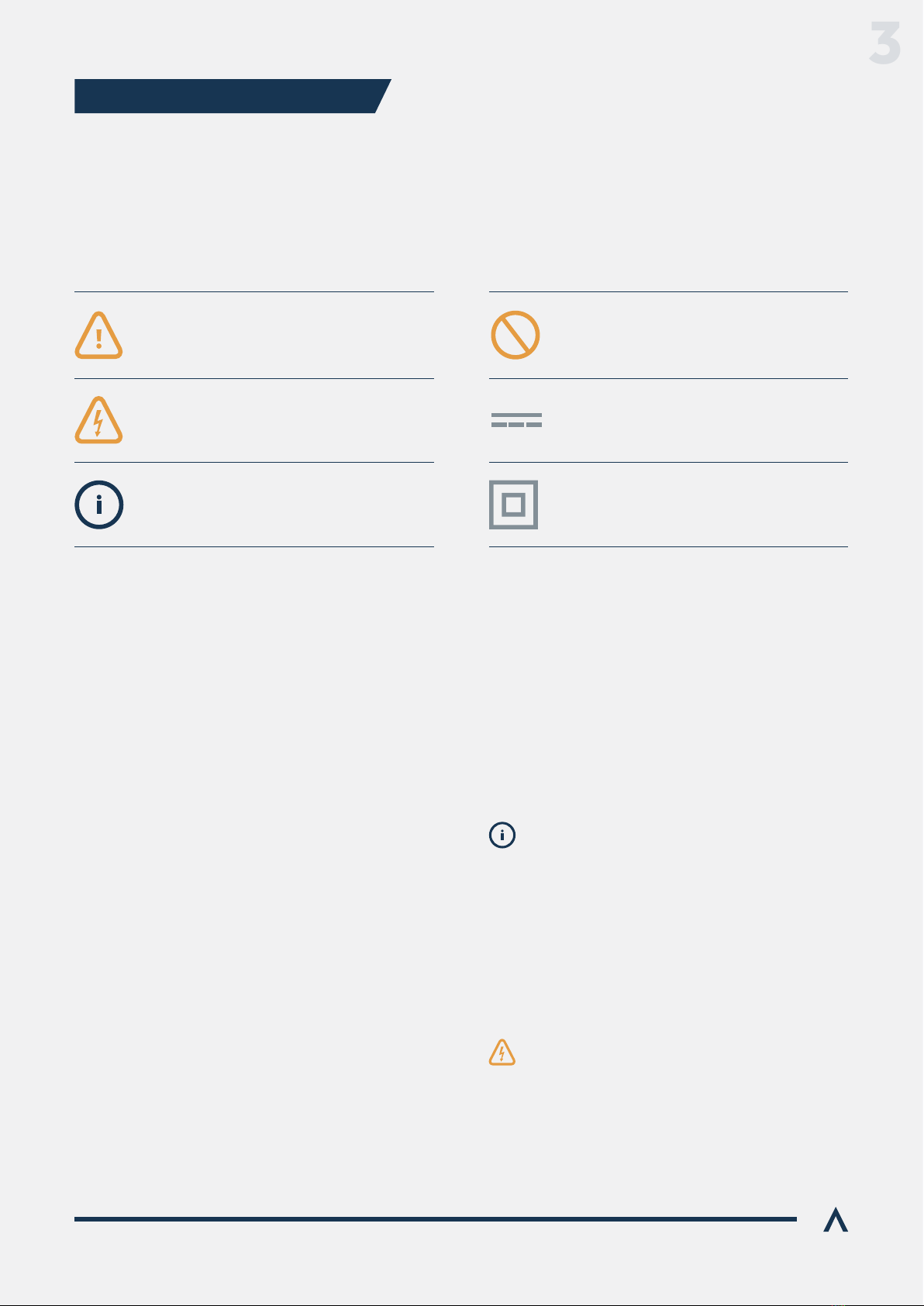
The following symbols are used in this manual to highlight and emphasise important information.
The general meanings of the symbols used in the manual, and those present on the device, are as follows:
These safety instructions are intended to highlight risks and dangers of improper installation, commissioning and use
of the SGS device.
Immediately after receiving the package, make sure that the packaging and the device have no signs of damage.
If the packaging shows any sign of damage or impact, damage of the SGS should be suspected and it should not be
installed. If this occurs, please contact Apex customer service.
This system should be installed, handled
meet all the safety-related standards, regulations
and legislation applicable to the installation and
operation of this system in the country concerned.
The responsibility to select qualied sta lies with
the company that the sta work for. It is also the
responsibility of the company to assess the ability
of the worker to carry out any kind of work and
ensure their safety. Sta must comply with
workplace health and safety regulations. It is the
responsibility of the company to provide their sta
with the training necessary for handling electrical
devices and to make sure that they familiarize
themselves with the contents of this user manual.
General Caution Prohibited
Direct Current
Reinforced Insulation
General Electrical Hazard
Information
3.1 SYMBOLS
3.2 PURPOSE
3.3 TRANSPORT DAMAGE CHECK
3.4 STAFF
The Apex SGS is designed to form part of a domestic
electrical installation. Applicable safety measures must be
observed, and any additional safety requirements should
3.5 SPECIAL HAZARDS
Dangerous voltages may be present in the system
and any physical contact could cause serious injury
or death. Please ensure that all covers are securely
fastened and that only qualied sta service the
Apex SGS. Ensure that the system is switched o
or disconnected during handling.
3. SAFETY INSTRUCTIONS
3
Solar Geyser System Manual 7
3.6 INSTALLATION LOCATION
The Apex SGS may only be installed indoors, vertically
excessive dust, corrosion and humidity. It should never be
installed directly below a geyser or in any location where
a potential water leak could occur.
See section 5 for more info.
3.7 ALTERATIONS
It is strictly prohibited to carry out any alteration
or modication to the Apex SGS or any of its
accessories.
Cleaning and maintenance should only be carried out with
the Apex SGS disconnected from the grid and PV supplies.
Before taking any action, make sure that the system has
been correctly disconnected by deactivating the circuit
breakers and or isolators that power it. To clean the SGS,
the SGS to dissipate heat generated.
3.8 CLEANING AND MAINTENANCE
Do not try to repair the device yourself in case of
any malfunction. If the need arises, contact Apex
customer service. The system does not require
any special maintenance, except for standard
physical cleaning to ensure good air ow and the
maintenance required by any electrical device
connected with screws and terminals that need
to be tightened.
The technology employed in the manufacturing of the
Apex SGS ensures safe handling and operation.
Nonetheless, the system might pose hazards if it is used by
this user manual.
Any person in charge of the installation, commissioning,
read and understand this user manual, especially the
safety recommendations and shall be trained to do so.
3.9 GENERAL HAZARDS RESULTING FROM
NON-COMPLIANCE WITH SAFETY STANDARDS
3.10 GENERAL SAFETY REQUIREMENTS
Operator
The person in charge of handling the electrical
device is responsible for the safety of persons
and property.
Insulate all the system’s power conducting
components which could cause injuries while
carrying out the work. Conrm that dangerous
areas are clearly marked and access is restricted.
Determine conclusively, using a voltmeter, that
there is no voltage in the system before
commencing work. Check all the terminals to
make sure that there is no voltage in the system,
on both AC and DC power interfaces.
Avoid accidental re-connection of the system
using signs, isolating locks and closing or blocking
the work site. Accidental reconnection may cause
serious injuries or death.
In all cases, local regulations shall be followed and take
preference over this manual or other documents related
to the Apex SGS. No part of this manual shall supersede
any local laws, bylaws or other regulations. These include
local electrical isolation requirements and so on.
3.11 LOCAL REQUIREMENTS
This device is exclusively designed to manage a hot water
geyser, to be powered by either the grid, a solar array or
The Apex SGS should only be used for this purpose. Apex
is not liable for any damages caused by inappropriate
installation, use or maintenance of the system.
To ensure safe use, the Apex SGS must only be used in
compliance with the instructions in this manual.
Legal and safety regulations must also be adhered to,
to ensure correct use.
3.12 OTHER CONSIDERATIONS
3

Solar Geyser System Manual 8
Figure 2 shows the front of the Apex SGS which has the
following features:
The SGS’s front fascia consists of 4 state indicating
multicolour LEDs. Below the LEDs is the cover over the
terminal chamber where all the cables terminate, which
is secured with 2 Philips head screws.
components.
It is designed to be mounted to the supplied bracket
This is the electrical interface to the grid supply.
geyser being supplied. The SGS can supply up to a 3KW
element, up to 15A at 230V AC.
This is the interface to which the geyser connects and is
marked “L” and “N“ on the main PCB.
The SGS accepts a single string of PV modules between
110 and 230VDC with a maximum Isc of 15A and is
connected with “MC4” connectors. The SGS will not
convert more than 1500W of PV power.
This is the temperature sensor which the SGS uses to
regulate the temperature of the geyser.
LEDs:
The front cover of the SGS features a set of multicolour
LEDs which are designed to indicate the state of operation
or errors.
GRID:
Indicates the status of the grid connection.
SOLAR:
Indicates the status of the PV / Solar connection.
STATUS:
Indicates the overall system status of the SGS itself.
TEMP:
Indicates the temperature status of the geyser.
FRONT:
REAR:
4.1 OVERVIEW AND DESCRIPTION
4.2 ELECTRICAL INTERFACES
Figure 2. SGS PV geyser system
The terminal chamber cover should only be
removed by electricians and accredited
installers who have correctly isolated the
system as described in the “Installation”
section of this manual.
The SGS has 4 electrical interfaces:
Grid
Geyser Element
PV
Temperature Sensor
when the device is in hotspot mode.
4.3 IDENTIFICATION
4. DEVICE DESCRIPTION
4
Solar Geyser System Manual 9
To install the SGS, follow these steps:
Not directly below the Geyser where it may be splashed by
any geyser leak event or in the case of maintenance work.
Begin by making sure that the AC supply is fully
isolated, either at the main breaker, RCD or
dedicated isolation device. Then ensure that the
DC PV supply is also fully isolated. Ensure that
supplies are locked out to prevent accidental
reconnection, as necessary.
5.1 SAFETY AND ISOLATION 5.3 ELECTRICAL INSTALLATION
As the SGS is installed into a building’s electrical
infrastructure and has both AC and DC power
supplies, it is necessary to ensure that the
installation area is secured and safe before
beginning the installation.
The SGS may not be mounted horizontally or at
an oblique angle. It must be mounted with the
terminal chamber at the boom of the font cover
(ie: correctly rotated)
The SGS may not be installed within the ceiling or
roof cavity.
hooks and sliding it downwards. There should be a small
gap between the bracket and the rear surface of the SGS’s
Note that the SGS will generate some heat and it is
necessary to take that into consideration when choosing
your installation location.
To begin your SGS installation, locate a suitable position
5.2 INSTALLATION OF THE SGS
• A rm, even vertical surface
• A location that is fully indoors
• Free from excessive dust and moisture
• Has free airow and at least 300mm clearance all around
• Is not subjected to heat generated by another device
• It may not be mounted inside a cupboard or other place
without free air ow.
• It may not be mounted inside a cupboard or other
place without free air ow.
• Is within reach of the 10m temperature probe’s
maximum length.
Note that the SGS can be used ogrid, without
an AC supply. In this case, ignore instructions
relating to the AC supply below, leaving the AC
Supply terminals open.
Note that, depending on where the SGS is
mounted, the following steps may dier.
Depending on whether this is a new or existing geyser
installation, follower either the steps labelled “Existing
installations” or “New installations” below.
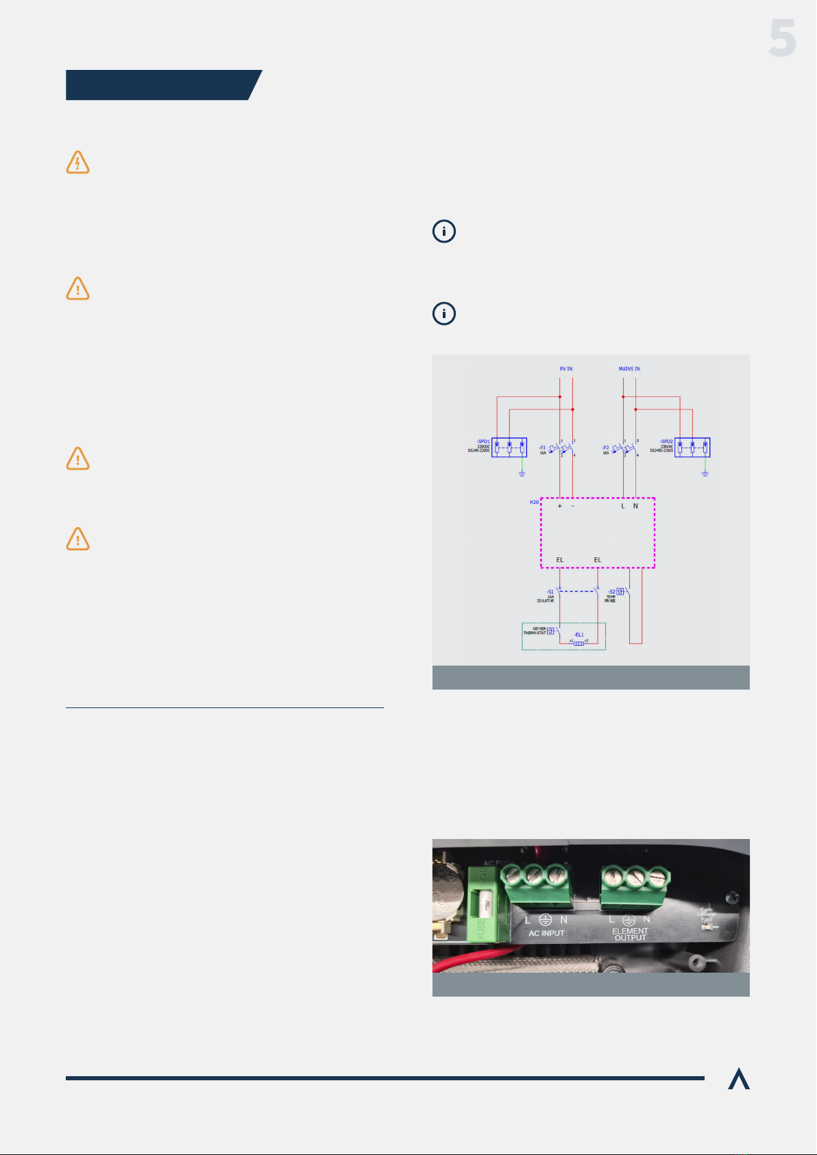
Figure 3. SGS Electrical Installation Overview
Figure 3. SGS Electrical Installation Overview
The SGS shall be installed with all the relevant electrical
protection and isolation. In particular, AC and DC protection
and local isolation is required, as well as AC and DC surge
protection.
Figure 3 shows a typical electrical layout.
5. INSTALLATION
5
Solar Geyser System Manual 10
Remove the power cable feeding the existing geyser from
the terminations inside the geyser’s terminal chamber or
local isolator at the geyser, according to local regulations.
This cable then becomes the power supply to the SGS
terminals on the PC board. Ensure that the Live, Neutral
and Earth conductors are all connected securely and
according to the labels.
Run a new cable of suitable cross section from the 2
terminal of the SGS’s PC board to the location where the
chamber or the local isolator, depending on local
regulations. Ensure that the Live, Neutral and Earth
conductors are all connected securely and according
to the labels on the Apex SGS and the Geyser.
Connect a supply from a suitably sized dedicated circuit
breaker in the distribution board with a suitable cross
section cable to the SGS. This cable is the power supply to
the SGS and is terminated at the “L”, “N” and earth (AC
Neutral and Earth conductors are all connected securely
and according to the labels on the PC board.
Run a cable of suitable cross section from the terminals
SGS’s PC board to the Geyser’s terminal chamber or the
local isolator, depending on local regulations. Ensure that
the Live, Neutral and Earth conductors are all connected
securely and according to the labels on the SGS and
the Geyser.
Ensure that the Geyser is fully earthed, according
to local regulations.
Ensure that the geyser’s thermostat is
correctly connected into the circuit, as per the
manufacturer’s instructions. This is an important
safety device and may not be omied.
AC Supply to SGS
DC PV Supply:
AC Supply to SGS
SGS to Geyser Supply
SGS to Geyser Supply
EXISTING INSTALLATIONS
NEW INSTALLATIONS
The DC supply shall be isolatable locally at the SGS for
both safety and convenience. This can be done either with
a suitably rated double-pole DC circuit breaker or isolator,
with a rating of at least 250V and 16A DC.
The Apex SGS should only be connected to a single, series
more than 15A. 2 parallel strings of panels are only allowed
when they are of the “High voltage” type, with a short
circuit current of less than 7A per string.
Before connection, check the polarity of the incoming PV
supply with a suitable DC test instrument to ensure that
the Apex SGS is not exposed to reverse polarity. Then,
with the PV Array exposed to full sunlight, check that the
PV voltage is within the allowable limits of 120 – 230V DC.
Ensure that the DC cables are correctly terminated into
original Staubli MC4 connectors only.
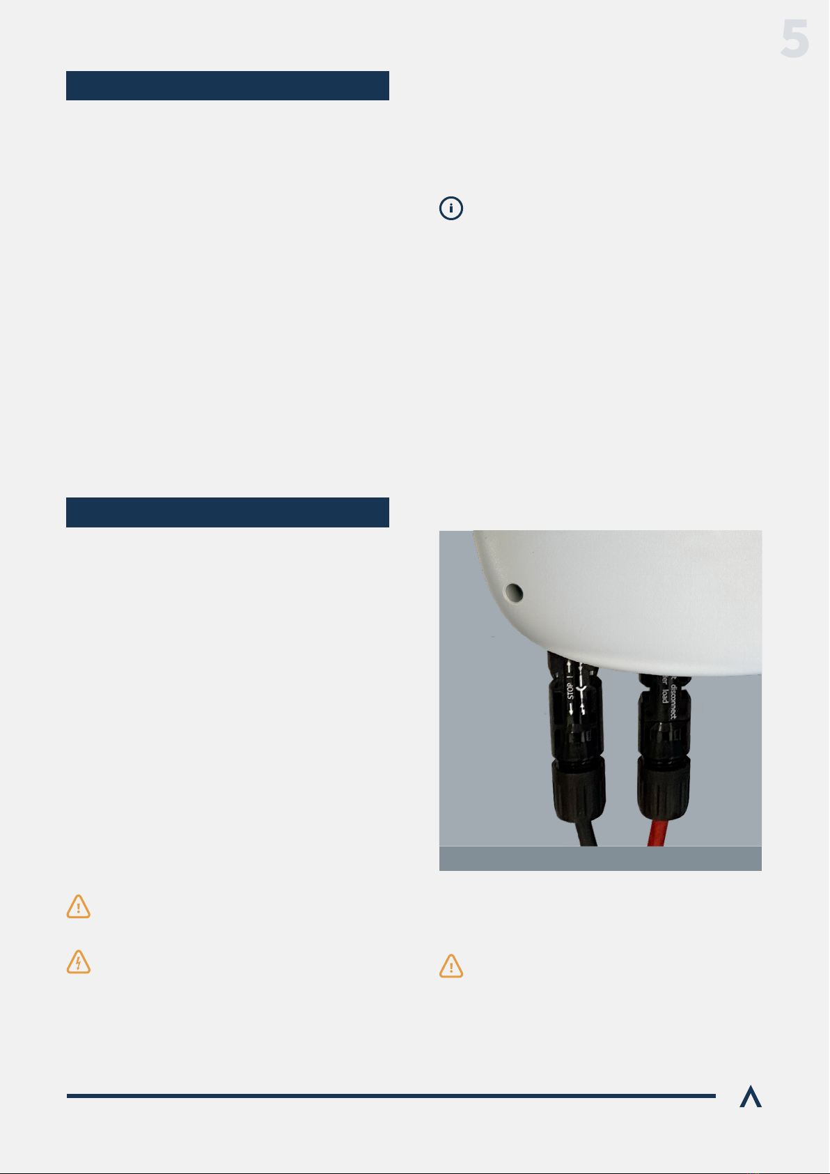
Now connect the DC PV power supply to the MC4
Note that if a DC breaker is used in this location, it
is not possible for it to trip on over-current events,
since the PV string cannot generate enough current
beyond its operational curve to do so.
Ensure that the SGS is protected with Surge
Protection Devices (SPD’s) on both the AC and
DC supply interfaces.
Figure 5. SGS DC input
5

Solar Geyser System Manual 11
The SGS is supplied with a temperature sensor designed
the existing thermostat.
The probe is made from industrial grade K-type
thermocouple wire with our patented, proprietary
temperature sensor. It consists of k-type wire leading
-
ducting heat to the junction.
Installing the collar is an easy process. Start at the geyser
and work towards the SGS. With the power to the geyser
feed the copper strip into the thermostat pocket, all the
way up to the collar.
Then feed the geyser thermostat through the centre of the
probe collar into the geyser pocket and push it all the way
in until the current carrying contacts of the thermostat
mate with the geyser.
Be careful not to damage the probe or its insulation as
you push the thermostat into place. It is important that
the temperature probe is correctly installed so that it
cannot be accidentally removed, thus causing an incorrect
temperature reading.
From there, the probe wire can be fed to the SGS,
avoiding other cables as far as possible to minimise
electrical noise being induced.
Set the geyser thermostat to maximum (usually 70
and the thermostat now only acts as a fail safe.
The SGS can heat water to scalding temperatures.
Depending on the installation, a mixing valve may
be required to regulate the temperature to safe
levels at the points of use. Consult local regulations.
Temperature Sensor
terminal. Push the temperature probe wires into that
terminal in the order that follows from left to right:
Red, Yellow
Figure 6. Temperature
sensor installation
Figure 7. Temperature sensor’s
connections to the SGS PCB
Now connect the other end of the probe’s cable to the
SGS’s PCB as shown in Figure 7.
The supplied temperature probe is 10m long.
Longer (or shorter) lengths can be manufactured
to order but need to be carefully routed to avoid
electrical noise being induced. Always take care
how you route the cable away from other cables
and electrical devices. Should spurious readings
occur, check your routing and move it away from
all other cables. In general, the shorter the cable
the beer the reliability of the reading.
Note that if the SGS does not power up from the
PV interface alone it is possible that the PV supply
polarity is not correct or that there is insuicient
power available on the panels.
Begin with the geyser switched on at its local isolator.
Since the SGS can be run on either power supply, its
power-up sequence is not critical. However, powering
The lights on the front of the SGS should illuminate if
correct. Now power up the AC interface.
5.4 POWERING UP THE SGS
5
Solar Geyser System Manual 12
set point using the power sources available to it.
In general, the PV interface is prioritised, and the SGS will
6.2 OPERATING MODES
Never power up a geyser without water in it.
When only the AC connection is on
– SGS will be on and will heat from grid.
When the AC connection is on and suicient solar power
is available
- SGS will be on and will heat from solar.
When the AC connection is on, but insuicient solar
power is available
- SGS will be on and will heat from grid.
When the AC connection is o and suicient solar power
is available
- SGS will be on and will heat from solar.
When AC connection is o and insuicient solar power
is available
- SGS system will shut down.
When suicient solar power is available
- SGS will be on and can heat.
When insuicient solar power is available
A generator may also be used on the input, in which case
the SGS will behave as described in the On-grid use case.
The SGS is designed to assume temperature control
of the geyser to which it is connected and operates
autonomously. However, the original thermal cut-out
device shall remain in place to ensure that, in the
unlikely event of a failure of the SGS, the system will
remain below dangerous temperature levels.
To do this, set the original mechanical thermostat to the
local regulations which may determine the maximum
allowable temperatures. Fit a mixing valve to ensure
that the water is a safe temperature at the point of use.
6.1 COMMISSIONING
BASIC USE CASES
BASIC USE CASES
The SGS can work directly out of the box with no further
be changes by connecting the SGS to a mobile device
Note: it is recommended that an internet connection
is used and commissioned as it enables full diagnostics
and conguration of the device. Alternatively, the local
hotspot’s web page can also be used to monitor and
control the device (see section 7.2)
AC setpoint
Solar setpoint
Boost setpoint
50°C
70°C
60°C
6.3 DEFAULT SETTINGS
6. COMMISSIONING & OPERATION
6

Solar Geyser System Manual 13
The SGS uses the front panel LEDs to indicate its status.
4 multicolour indicators are used and their colours designate the following possible statuses:
If the SGS does not work correctly or displays a fault is present with the Status LED, it is necessary to correct an abnormal
on both PV and AC together.
The following table shows monitored faults which can occur and possible solutions:
contact our Support department.
6.4 LED STATUS INDICATORS
6.5 FAULT FINDING
Temp LED
Heating
At setpoint
Cooling
Solar heating
Grid mode
Solar o
Grid heating
Solar mode
Grid o
AP mode
Wi-Fi connected
AP mode
Wi-Fi connected
Solar LED Grid LED Status LED (2 colour ash)
No Error0
PV over voltage2
Water over temp4
No temp probe detected5
Temperature error6
Safety cut out activated7
Thermal cut out8
NTC fault
Relay fault
9
10
Leakage detected3
System normal
DC input voltage too high
Over max Temperature detected
Temperature probe is not connected
Implausible temperature reading
Temp or RCM safety active
Max temperature limit reached
SGS Internal over-temperature
Relay fault detected in SGS
RCD has detected leakage current
N/A
Too many PV panels in series
Return for repair
Connect probe
Check probe installation
Check for faults
Check system
System too hot, check operating
environment
Return for repair
Check for electrical faults,
particularly at the geyser element.
Error Name Description Action
Normal
Normal
Error
Error
6
Solar Geyser System Manual 14
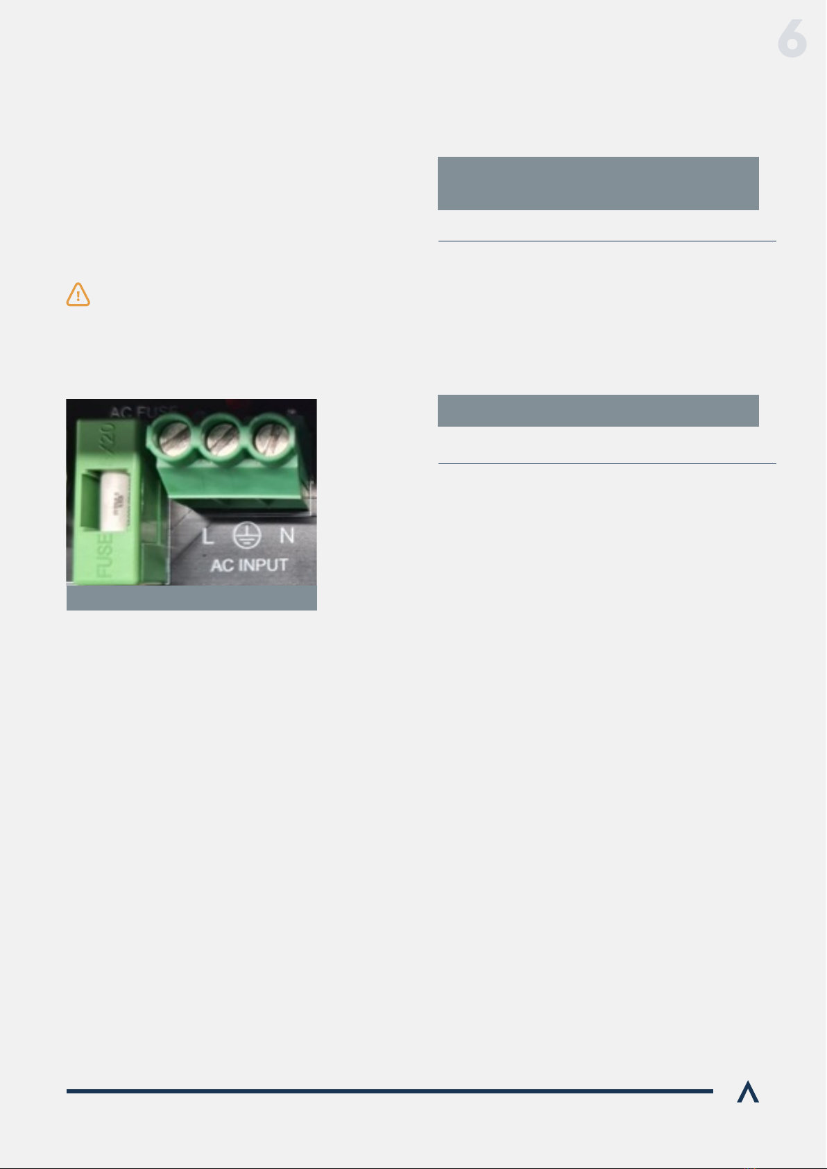
6.6 OTHER ERRORS
The Apex SGS has 2 fuses inside, 1 each for the AC and DC
supplies. Should either supply fail to correctly power
up the unit, check these 2 fuses on the main board.
Due to the nature of the probe, it is important that it is
very carefully handled, installed and well routed. In
and that it is not too tight or too loose. If the probe is
damaged, the Apex SGS will enter an error state which
of the probe’s PCB connector.
If this LED illuminates, it is likely that the probe is
damaged. Remove the probe and inspect it for insulation
damage and, if necessary, replace it.
It is designed to detect current leakage on the output
above 30mA, and it will shut the Apex SGS down into a
safe state. In such circumstances, the DC array, geyser
and AC supply should be treated with great care and
the fault located and corrected urgently.
Fuses:
Temperature Probe:
Leakage Current:
Fuses should only be replaced with the
original size / specication devices.
Failure to do so could result in dangerous
electrical failure and will invalidate any
warranty claim.
If the SGS is damaged, becomes faulty or in any way fails
to work correctly, it will require repairs by Apex.
The Apex SGS is warranted to be free from defects
for a period of 1 year from purchase, subject to Apex’s
Warranty terms and conditions, a copy of which is
available at:
6.7 SERVICE, SUPPORT AND REPAIRS
6.8 WARRANTY
To request support or an RMA number please go to
www.ApexSolar.Tech
www.ApexSolar.Tech
errors may also occur:
Figure 8. AC Fuse
6

Solar Geyser System Manual 15
7.1 APP INTRODUCTION
included cloud application, which works on Android, iOS
and desktop computers. The applications can be viewed
as web pages or installed and work just as any other app.
After opening the provided link in a mobile device’s web
browser, depending on your browser / device, you can
install the Web app to your home screen, just like any other
app. The process for this varies from browser to browser,
but the general idea is the same. Here are the instructions
for popular web browsers.
After loading the link in the browser:
Installing the Apex SGS’s App:
is the “Add to Home screen” icon. Tapping this will show a
adding the app to the Home screen.
Note that in Android 8 and higher an “Add to Home
Safari browser supports web apps. To add a web app to
opens the sharing panel. Among the options is the “Add
to Home Screen” option. Choosing “Add to Home Screen”
that the user wants to add the app to the home screen
and lets them customize its name.
Tap “Add” and the app is now included on the home screen.
You’ll see a circular icon with a downward facing arrow
next to the address bar. Tapping the icon will show a
app to your home screen.
You’ll see an install banner pop up asking whether you
want to add this app to your Home screen. If you choose
not to add it to your Home screen at this point, you can do
so later using the “Add to Home Screen” icon in the main
Chrome menu.
Using the 3 dot drop-down, tap “Install app” in the
menu list.
It can be found at
www.ApexSolar.Tech
ANDROID DEVICES
IOS DEVICES
Firefox
Samsung Internet
Chrome for Android
Other Browsers
A new Apex SGS will start up with its own Wi-Fi hotspot
active and this is indicated by the Status LED on the SGS
colour, about once per second.
hotspots with a mobile device and searching for one with a
name that contains “SGS” and the SGS’s MAC address,
For example SGS_aa94bc5633.
Select the hotspot that corresponds to that name; the
password is 123456789. Once you have joined that
The username and password are “guest” and “guest”.
Once in the webpage, the dashboard is the default page
from which one can see geyser temperature and a few
pieces of live telemetry.
You can also control the device, set new temperature
7.2 CONNECTIVITY
7. MOBILE APPLICATIONS & WIFI CONNECTIVITY
7
Solar Geyser System Manual 16
7.2.1 WEB APP AND REMOTE ACCESS
The Apex SGS needs to be connected to a local Wi-Fi
network with internet access for the Web App to work.
In the side bar, navigate to “Wi-Fi Connection”. From
there, click on Scan networks to allow the device to be
connected to the Wi-Fi. Select the chosen Wi-Fi network
and type in its password and click save.
and the colour corresponding to its status to indicate that
it has successfully joined the hotspot. You can now use the
Web App and you are now connected to the cloud (but not
tab. The local portal will now also be available at the IP
address shown on your page. Please note that the IP
address does change from time to time unless you set
a static IP address.
To start using the Web app, navigate to
hps://Monitor.ApexSolar.Tech and sign in
The same web app is used for installers and users, though
with varying permissions. All functions detailed in the users
remote monitoring section in the following chapter apply
to the installers remote monitoring.
An Installer needs to have an account registered on
SGS’s server once they have been accredited, with a
username and password.
via support@rubiconsa.com
Once accredited, an installer can enrol a site by logging in
with the credentials you were supplied.
7.3 INSTALLERS REMOTE MONITORING
Once the installers account has been created, the installer
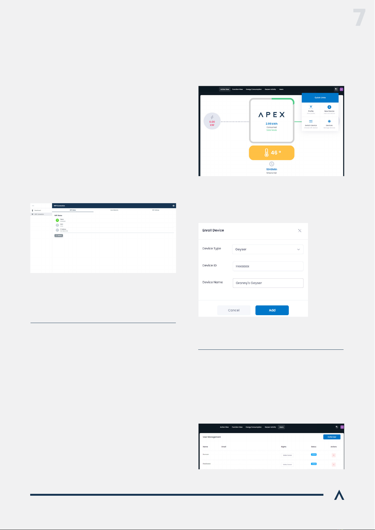
can sign in and is able to enrol a new device. At the top
then click New Device.
The enrolment information can be entered into the form
as shown. The device ID is found on the local portal of the
Device Type, Device ID and a meaningful Device Name.
Once the device has been successfully added, you’ll be
able to view its live and historical telemetry.
7.3.1 ENROLLING A DEVICE
Once enrolled, a device can be shared with a user by
navigating to the Users page. By clicking Invite User, you
will be able to enter the user’s email address and send an
invite to them. They will receive a welcome email which
they can follow to set up an account and view the site.
7.3.2 INVITING A USER
7

Solar Geyser System Manual 17
Apex SGS is managed, monitored and controlled with the
SGS web app.
The Application requires an Apex SGS’s user to have been
with them before they can view the site. Please contact
your installer or Apex’s Support if you have not yet been
enrolled. Once they have been enrolled, a new Apex SGS
owner’s installer can share this link and they can then open
it with their mobile device’s browser.
7.4 USER’S REMOTE MONITORING
The primary view of your Apex SGS is the “Active View”.
This gives an overview of the status of the device,
including current active power sources, geyser
temperature and overall status. The Active View is
shown below. In the centre, there is an energy counter in
kWh that shows the total energy used to heat the geyser
that day. The green/grey pie graph around the centre
depicts the quantity of that energy derived from solar
The Function View is where you can interact with your
Apex SGS.
hps://Monitor.ApexSolar.Tech
Menu: Function View
This view allows you to visualise your energy usage
period. To view the graph, select a start and end date
and then tap Get Data. It is also possible to view the last
7 days’ history in bar graph format by tapping the Seven
Days tab.
The Geyser Activity view enables the user to view the
geyser’s temperature and heating cycles by source
graphically over a period.
To create a graph, select start and end dates and then tap
Get Data. Once the graph is displayed, you can turn each
or solar icons.
Boost
Turn Grid O:
Away:
Notications:
Seings:
Support:
The Apex SGS will heat the water to the Boost setpoint in
the shortest possible time, which will use AC power. Tap
again to deactivate Boost.
This disables the use of grid power for heating your water,
even if it is available. Tap again to deactivate.
This will stop heating your water from all sources until
deselected and the SGS is in standby. Tap again to
deactivate Away mode.
You can change the temperature setpoints for Grid, Solar
and Boost modes here.
Contact Apex for support from here.
Menu: Geyser Activity
Menu: Active Menu
Menu: Energy Consumption
7

18Solar Geyser System Manual
www.ApexSolar.Tech
For more or updated information, new products and technical support please visit:
8. Contact us
This manual suits for next models
1
Table of contents
Popular Water Heater manuals by other brands

Sunerg Solar Energy
Sunerg Solar Energy Calor Top 200D Installation & owner's manual

Rinnai
Rinnai HD28E Operation & installation manual

STIEBEL ELTRON
STIEBEL ELTRON CF 12 KW Operation and installation

Webasto
Webasto Thermo 50 operating instructions

Noritz
Noritz GQ-C3257WX US owner's guide

Zip
Zip DEX Installation, maintenance and user instructions


