Aphex FM Pro 2020 Instruction and safety manual

Web Version
Model 2020 FM Pro Audio Processor Page C-1
Aphex Model 2020
FM Pro
Operating & Service Manual
Manufactured By
Aphex Systems Ltd.
11068 Randall St.
Sun Valley, California 91352
U. S. A.
5,424,488
5,422,602
5,359,665
5,334,947
5,155,769
5,930,374
5,898,395
5,896,458
5,848,167
5,737,432
5,612,612
5,485,077
5,483,600
5,463,695
5,450,034
5,115,471
4,939,471
4,843,626
4,633,501
4,578,648
The Model 2020 is protected under one or more of the following U. S. Patents:
Copyright 1995-2000 Aphex Systems Ltd. All rights reserved.
All Aphex product names are trademarks or registered trademarks of Aphex Systems Ltd. Other brand and
product names mentioned within the manual are trademarks of their respective owners.
Updates to this manual and other important information about the Model 2020 may be found at:
http://www.aphex.com

Web Version
Model 2020 FM Pro Audio Processor Page C-2
Once the unit is installed, here’s the proce-
dure to get your FM Pro operating properly
using a factory preset. You can later create
your own presets if you wish.
Step 1, Understanding The Menus. The
escape key backs you out of menus and
commitments. It continuously takes you back-
wards towards the Main menu. The enter key
selects menu items and makes commitments
such as save and recall. The up and down
cursers generally move the menu pointer while
the left and right cursors generally flip through
multiple menu pages. The Spin dial acts
as an adjustment control to set menu values.
FM Pro Quick Setup Guide
All menus branch from the Main menu. Each
menu may have one or more sub menus. The
menu tree is so logical and easy to discover
that within a few minutes you will be very
comfortable with it.
Step, Setting Up Globals. Go to the process-
ing menu, and, by navigating through the
submenus, set up the "Global Parameters" to
match your system’s operating requirements.
The menus will state that a feature is unavail-
able if the associated option is not installed
in the FM Pro.
Important: Once the Globals are set, save to
the Global preset, U01, by going to the “Save
Preset” menu.
Step 3, Select A Preset. There are
8 factory presets designed for various
programming formats. Chose one that
approximately matches your station’s
format. If you are not sure, chose “Big
Country” as a moderately aggressive
starter. If you want to really risk it,
chose “CHR” and get a very loud and
intense air sound.
Step 4, Adjust The Output Level.
While sending program audio to the
FM Pro, adjust the analog line output
(Input/Output menu) for the required
peak output level. If you are using
the PPDM multiplex option, adjust the
multiplex output level (back panel trim)
for 100% peak modulation of your
transmitter.
The Global Parameters
A. Processing Menu, Input/Output Menu pages 1,2,3
Input reference level
Peak output level
Unit bypass on/off
20Hz High Pass Filter on/off
16.5kHz Low Pass Filter on/off
Spectral Phase Refractor (SPR) on/off
Stereo Insert on/off
Input Source: A or D
Output: A, D, or A&D
B. Processing Menu, Pre-emphasis Limiter Menu
Pre-emphasis filter, 50 or 75 microsecond
De-emphasis on/off
C. Processing Menu, Stereo Generator Menu pages 1,2
Pilot Mix percentage
Pilot on/off
Input mode: Stereo, Mono (L, R or L+R)
Mono Mode 90% or 100%
D. Processing Menu, AES Status
Transmit rate: Slave, 32, 44.1, or 48kHz
Notice
Following this guide will get you up and running but without much understanding of what
you are doing. We highly recommend at least a minimal study of the manual. It is written
for fast and easy reading.
That’s It!

Model 2020 FM Pro Audio Processor Page 1-1
Web Version
1.0 Table of Contents
2.0 Product Description
2.1 The FM Pro Story
2.2 Description
2.3 Applications
2.4 Table of Options
2.5 Feature List
3.0 The User Interface
3.1 Metering and Status
3.1.1 Input Meter
3.1.2 Leveling Meter
3.1.3 Multiband Compressor
3.1.4 Limiter
3.1.5 Status Indicators
3.1.5.1 16.5 KHz Lowpass Filter
3.1.5.2 20Hz Highpass Filter
3.1.5.3 75 uSec Indicator
3.1.5.4 SPR
3.1.5.5- HF Limiter
3.1.5.6 Analog In
3.1.5.7 Digital In (Optional)
3.1.5.8 Data Present
3.1.5.9 DVG
3.1.5.10 Sil. Gate (Silence Gate)
3.1.5.11 Lvl. Stic. (Sticky Leveler)
3.1.6 Multiband Coupling
3.1.6.1 L><R Hard
3.1.6.2 L><R Elast. (L><R Elastic)
3.1.6.3 1><2
3.1.6.4 2><3
3.1.6.5 3><4
3.1.7 Output Status LEDs
3.1.7.1 Analog
3.1.7.2 Digital
3.1.7.3 Bypass
3.1.8 LCD Display
3.2 Front Panel Controls
3.2.1 Spin Dial
3.2.2 Navigation (Cursor) Buttons
3.2.3 Esc (No), Enter (Yes)
3.2.4 Input, Output Monitor
4.0 Navigating The Menus
4.1 Introduction To The Menu Display
4.2 Menu Display Features
4.2.1 Header
4.2.2 Menu Selections
4.2.3 Footer
4.3 Display Sleeping Mode

Model 2020 FM Pro Audio Processor
1.0 Table Of Contents
Page 1-2
Web Version
4.4 Password Security Page
4.5 Main Menu Page 1 of 2
4.5.1 Password Menu
4.5.1.1 Edit Password
4.5.1.2 View Password
4.5.1.3 Log in
4.5.1.4 Log out
4.5.2 Presets
4.5.2.1 Recall Preset
4.5.2.2 Save Preset
4.5.2.3 View list
4.5.2.4 Day Parting
4.5.2.4.1 Edit Day Parting
4.5.2.4.2 View parting
4.5.3 Processing
4.5.3.1 Processing Menu Page One
4.5.3.1.1 Input/Output Menu
4.5.3.1.2 Leveler/Gate Menu
4.5.3.1.3 Multiband Compressor Menu
4.5.3.1.4 Limiter/Bass Menu
4.5.3.2 Processing Menu Page Two
4.5.3.2.1 Preemp-Limiter Menu
4.5.3.2.2 Stereo Generator Menu
4.5.3.2.3 AES Status Menu
4.5.3.2.4 More or Less! Menu
4.5.4 Remote Link
4.6 Main Menu Page 2 of 2
4.6.1 Set Unit Time Menu
4.6.2 Display Mode Menu
4.6.3 Options Page
4.6.4 Unit Info Page
5.0 Detailed Audio Processing Description
5.1 Processing Overview
5.2 Generalized Processing Structure
5.3.1 Input Selection
5.3.2 Filters
5.3.2.1 20Hz Highpass Filter
5.3.2.2 16.5KHz Lowpass Filter
5.2.2.3 Spectral Phase Refractor (SPR)
5.3.2.4 Pre-emphasis Assist Equalizer
5.4 Frequency Discriminate Leveler (FDL)
5.4.1 Silence Gate
5.4.2 Dynamic Verification Gate DVG
5.4.3 Sticky Leveling
5.4.4 Jump Ahead
5.4.5 Attenuation Lock
5.4.6 Gain Lock
5.4.7 Leveling Rate Control
5.4.8 Frequency Discrimination
5.5 Insert Loop

Model 2020 FM Pro Audio Processor
1.0 Table Of Contents
Page 1-3
Web Version
1.0 Table Of Contents
5.6 The Multiband Compressor
5.6.1 Post Crossover Method
5.6.2 Wave Dependent Compression (WDC)
5.6.3 Peak Accelerated Compression (PAC)
5.6.4 Adjustable Crossovers (Band Filters)
5.6.5 Output Mixing
5.6.6 Adjustable Release Timing
5.6.7 Band Coupling
5.6.8 Stereo Coupling
5.6.9 The VCA Technology
5.7 Split Band Bass Processor/Limiter
5.7.1 Warm Bass Equalizer
5.7.2 Sub Bass Equalizer
5.7.3 Phase Coherent Crossover
5.7.4 Split Band Clipper (SBC)
5.8 Brightness Processor
5.9 Pre-emphasis Limiter
5.10 PPDM Stereo Generator
5.11 Digital I/O Module
6.0 Setting Up Processing
6.1 Steps In Setting Up
6.2 Targeting Processing Goals
6.3 Create the Global Preset
6.4 Select A Factory Preset
6.5 Adjusting the Processing
6.6 Leveling
6.6.1 Control Locks
6.6.2 DVG
6.6.3 Sticky Leveler
6.6.4 Silence Gate
6.6.5 Leveling Rate
6.7 Multiband Compression
6.7.1 Crossovers
6.7.2 Multiband Drive
6.7.3 Band Release
6.7.4 Band Mix
6.7.5 Band Coupling
6.8 Peak Limiting
6.9 Bass Enhancement
6.10 Brightness Enhancement
6.11 Pre-emphasis Limiting
6.12 Save Your Preset
6.13 Tutorial: A “HOW TO” Experience
7.0 All About Presets
7.1 What Are Presets?

Model 2020 FM Pro Audio Processor
1.0 Table Of Contents
Page 1-4
Web Version
7.2 What You Can Do With Presets
7.2.1 Recalling Presets
7.2.2 Saving Presets
7.2.3 Viewing Presets
7.2.4 Day-Part Scheduling
7.3 The Auto Save Feature
7.4 Do I Really Need To Create Presets?
7.5 Classes Of Presets
7.5.1 Factory Presets
7.5.2 User Presets
7.5.3 Global Preset
7.6 Tutorial--Building And Using Presets
7.6.1 Menu Navigation
7.6.2 Recalling A Preset
7.6.3 Saving A Preset (and making the global preset)
7.6.4 Day Parting (F4)
7.7 Summary
8.0 Password Security System
8.1 Why A Security System?
8.2 Log-in Access
8.3 Logging Out
8.3.1 Manual Log Out
8.3.2 Auto Lock Out
8.4 Auto Save
8.5 Password Enabling
8.5.1 Software Password Enabling
8.5.2 Hardware Password Enabling
8.6 Access With Lost Password
8.6.1 Clearing The Password Memory
8.7 Setting The Password
8.8 Clearing The Password
9.0 Using Digital Audio
9.1 Connecting AES/EBU Lines
9.1.1 Cable Pinout
9.2 AES/EBU Synchronization
9.3 Digital-To-Analog Conversion
9.4 Auto Source
9.5 Digital Output
9.6 Facts About Digital Audio, Bit Rate Reduction and Dynamics Processing
10.0 Using Multiplex
10.1 Stereo Generator Option
10.2 The Stereo Generator Menus

Model 2020 FM Pro Audio Processor
1.0 Table Of Contents
Page 1-5
Web Version
10.3 Presets Memory
10.4 Mode Settings
10.4.1 Mono Modes
10.4.2 Stereo Mode
10.5 Pilot Function
10.6 Multiplex Output
10.7 Multiplex Cable Connections
10.8 Modulation Overshoot Problems
10.8.1 STL Problems
10.8.2 FM Exciter Problems
10.8.3 Composite Clippers
10.9 Using RDS Encoders
11. Remote Operation
11.1 Hardware Requirements
11.2 Software Installation
11.3 Cable Wiring
11.3.1 Direct Connection
11.3.2 Modem Connections
11.3.2.1 Modem To FM Pro
11.3.2.2 PC To Modem
11.4 Operation By Modem
11.4.1 Usable Modem Types
11.4.2 Modem In The Windows Operating System
11.4.3 Modem Installation Procedure
11.4.4 Troubleshooting The Modem
11.4.5 Compatibility Issues
11.5 The PC Remote Control Main Form
11.5.1 Link Status
11.5.2 Transmit Speed
11.5.3 Receive Speed
11.6 Port Direct Linking
11.6.1 A Note On Day Parting
11.7 Modem Linking
11.8 Using The Remote Control Panel
11.9 Dealing With Presets
11.9.1 Recall Preset
11.9.2 Save Preset
11.10 The View Menu
12. Product Specifications
12.1 Getting Meaningful Numbers
12.2 FM Pro Setup
12.3 Test Equipment Connections
12.4 The Specifications
12.4.1 General Analog
12.4.2 Analog Input

Model 2020 FM Pro Audio Processor
1.0 Table Of Contents
Page 1-6
Web Version
12.4.3 Analog Line Outputs
12.4.4 Digital Inlut
12.4.5 Digital Output
12.4.6 Composite Baseband Output
12.4.7 Remote Control Interface
12.4.9 Physical
12.4.10 Environmental
13. Test & Calibration
14. Installation Instructions
14.1 Unpacking
14.2 Damage & Claims
14.3 Mains Voltage and Fuses
14.4 Power Cord
14.6 Mounting In A Rack
14.6 Proper Ventillation
14.7 Safety Considerations
14.8 Analog Balanced I/O
14.8.1 Standard Wiring
14.8.2 Main Input Wiring
14.8.3 Main Output Wiring
14.8.4 Insert Loop I/O Connections
14.9 Digital Audio I/O
14.10 Multiplex Output
14.11 RS-232 Connector
14.12 Summary
15. Schematics
16. Parts List
17. Service & Warranty Information
17.1 Obtaining Service For The FM Pro
17.2 Warranty Claims
17.3 What Is Covered
18. Web Broadcasting Applications
18.1 Why Process the Audio?
18.2 Basics of Processing
18.2.1 Leveling
18.2.2 Peak Limiting
18.2.3 Designing the Sound
18.3 Getting the Best Processing

Model 2020 FM Pro Audio Processor
1.0 Table Of Contents
Page 1-7
Web Version
18.4 Digital Versus Analog Processing
18.5 How to Use the Model 2020
18.5.1 Set the Input Level
18.5.2 Set the Output Level
18.5.3 Set Up the Processing
18.6 Bit Rate Effects

Model 2020 FM Pro Audio Processor Page 2-1
Web Version
2.1 The FM Pro Story
Aphex entered the world of broadcast audio pro-
cessing with the Type II Aural Exciter in 1981.
Since then Aphex has continued developing lead-
ing broadcast audio products. The Compellor
became and remains the world standard automatic
level controller. The Dominator became the world
standard multiband peak limiter. The Digicoder,
the only patented stereo generator technology, took
its place as the world’s best stereo generator.
Together the Compellor, Dominator, Aural Exciter,
and Digicoder comprise the Aphex Audiophile Air
Chain which has gained worldwide recognition
as the premiere FM audio processing system for
transparent, lifelike transmission of sound. World-
wide, many leading broadcast institutions have
adopted these Aphex products as their technical
standard and continue to employ them exclusively
in high grade radio and television network sys-
tems.
As proud as we are of the Audiophile Air Chain
and what it achieves in its sonic purity, we realize
many broadcast applications demand something
else. For example, a need exists to literally design
the sound of a radio station, i.e., to generate a
unique and competitive air sound intentionally
modified in certain ways. Also, the processor
may be required to operate directly within a
digital audio path. Furthermore, there is a demand
for programmability, remote control, and day-part
automation. We developed the FM Pro to fulfill
all these needs and more. Naturally, we borrowed
upon many of the proven and exclusive Aphex
patented circuits to achieve a technically excellent
design, but while we were at it we invented at least
six additional new and innovative audio process-
ing concepts giving the FM Pro truly advanced
capabilities and performance.
2.2 Description
The FM Pro is not just a boxed-up combination
of prior Aphex products. It is a totally new
and advanced audio processing system tailored
especially to the demands of FM broadcasting.
Competition ready, the FM Pro is completely
adjustable from detailed and neutral to heavy and
loud. Thanks to the numerous design innovations,
even at extreme settings exceptional audio quality
is maintained. Unlike the competing digital or
analog audio processors which afford relatively
little flexibility, the FM Pro is a virtually sound
2.0 Product Description
designer’s palette allowing you to paint a truly
unique and competitive on-air sound. Don’t be
misled, however, the FM Pro can just as well be set
up to sound as neutral and transparent as desired.
Modular design makes the FM Pro space-saving
and cost efficient compared to other processors.
Plug-in options are easily field installed and can
be shipped to specification. Sixteen recallable user
presets are provided for manual selection or day-
part automation. For convenience, eight factory
presets covering a variety of formats are built-in
to get you up and running quickly. Day-part
automation is completely self-contained and driven
by an accurate internal clock/calendar timer. Front
panel operation is made easy and intuitive through
the logical menu tree. An RS232 port permits
remote control and monitoring of the FM Pro from
almost any location through the use of a standard
personal computer and a serial cable or modem.
A simple but effective supervised password system
can be engaged to maintain security over the FM
Pro’s operation. Fail-safe operation is assured
by a power-off internal relay bypass of both the
analog and digital audio I/O circuits. Power-up fast
recovery gets the FM Pro back on line with all
programmable parameters set correctly and operat-
ing in just a few tenths of a second. The front panel
displays are more than token indicators. They
indicate the actual operation of all major process
functions in real time.
2.3 Applications
The flexibility of the Aphex FM Pro makes it
suitable for nearly every FM broadcasting entity
from government owned to purely commercial.
Whether your audio system contains analog, digital
or both formats, the FM Pro can be configured to fit
in perfectly. Fully adjustable parameters allow you
to optimize the FM Pro for any program format:
classical music, talk, even heavy metal. Automated
transformation of processing parameters by the day,
hour, and minute allow radio stations with varying
formats to tailor the FM Pro exactly as required for
each day-part. Although the FM Pro is intended
mainly for FM broadcasting, it will find many
interesting applications in other fields where abso-
lute audio control and flexible sound tailoring are
desired. Digital and analog mastering, recording,
satellite uplinks, and amplified sound are just a
few examples.

Model 2020 FM Pro Audio Processor
2.0 Product Description
Page 2-2
Web Version
Analog
Stereo
Input
Analog
Stereo
Output
AES/EBU
I/O
PPDM
MPX
Output
Pre-Emp
Limiter
2.4 FM Pro OPTIONS
Basic X X
Option 1 X X X
Option 2 X X X
Option 3 X X XX
1. Analog and Digital Stereo Inputs
2. Input processing functions
a. 20Hz Highpass Filter
b. 16.5KHz lowpass filter
c. SPR process
d. Selectable external processing loop patch
3. Frequency Discriminate Leveler
a. Improved parametric controls
b. New “sticky” leveling feature
c. Selectable patented “DVG”
d. Selectable silence gate
e. Adjustable silence gate threshold
f. Adjustable AGC upper and lower control limits
4. Multiband compressor
a. 4-bands
b. adjustable crossover frequencies
c. Easyrider compression
d. “Peak Accelerated Compression” (PAC) algorithm
e. Band-by-band stereo elastic coupling
f. Band-to-band forward elastic coupling
g. Adjustable compression drive
h. Separate adjustable release time per band
i. Selectable stereo hard coupling
j. Compression drive control
k. Output band mixing facility
l. New “post crossover” multiband technique
m. High or Low selectable ratio
5. Bass Processor
a. Distortion canceled bass clipper
b. “Warm bass” equalizer
c. “Sub Bass” equalizer
d. Total “Bass Mix” control
6. Peak Limiter
a. Bass interactive to reduce intermod distortion
b. Instant processing, i.e., no pumping
c. Zero overshoot
d. Master drive control configures loudness factors
7. Optional pre-emphasis processor
a. Special 50 or 75 microsecond pre-emphasis filter
b. Digicoder type pre-emphasis limiter
c. Digicoder type non-overshoot final lowpass filters
d. Output ready for any stereo generator
8. Optional digital I/O module
a. AES/EBU format up to 20 bits
b. Selectable output sample rate: 32K, 44.1K, 48K
c. Auto “lock on” for input rates of 32K, 44.1K or 48K
d. Input and output sample rates separately selectable
9. Optional Digicoder stereo generator module
a. Digicoder type PPDM stereo generator
b. Analog multiplex output
c. stereo/mono mode switching
d. Pilot on/off
e. trimmable multiplex output level
10. Digital remote control
a. RS232 digital interface
b. Windows 3.1 or 95 virtual control panel software
c. Complete operating capabilities
d. Complete visual real time meter displays
e. Password security options
11. Front panel user interface
a. LCD graphics panel display
b. Password security features
c. Rotary encoder knob
d. Up/Down, L/R cursor buttons
e. Menu selection system
f. Real time LED bargraph meters for:
1. Leveling
2. 4-band compression
3. Limiting
4. Stereo input VU
g. Real time LED indicators for:
1. 16.5KHz Lowpass
2. 20Hz Highpass
3. 50/75uS Pre-emphasis
4. SPR
5. Analog In selected
6. Digital in selected
7. Digital data presence
8. DVG
9. Sticky on/off
10. Silence gate
11. L><R hard couple
12. L><R elastic couple
13. 1><2 couple
14. 2><3 couple
15. 3><4 couple
16. Analog output presence
17. Digital output presence
18. Bypass on/off
h. Headphone monitor selector
1. Monitor input signal & volume
2. Monitor output signal & volume
2.5 FUNCTIONS AND FEATURES

Model 2020 FM Pro Audio Processor Page 3-1
Web Version
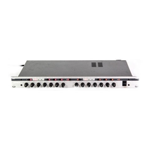
Figure 3-1 illustrates the front panel features of the
FM Pro. You may refer to that diagram for a quick
summary of all available controls and indicators.
The following description, taken in conjunction
with the diagram, will give you a very good
understanding of all the features and controls, their
purpose and use.
3.1 Metering and Status
While other processors provide only drab, jittery,
and inaccurate LCD meter displays and tell the
status of structural functions only on buried menu
pages, the FM Pro provides the user with colorful
front panel metering that is true and easy to read.
The major dynamic processes are metered by real-
time LED bar graph displays while the on/off
status of static functions are indicated by single
LED’s. The state of all major functions of the FM
Pro can therefore be observed at any time with one
one glance at the front panel.
Following is a more detailed description of all the
panel indicators.
3.1.1 Input Meter
Two yellow 10-segment bargraph meters are pro-
vided to indicate the stereo audio input level rela-
tive to the current input reference setting. The scale
indicates from -18dB to +9dB in 3dB steps.
Note: The input reference level is adjusted in the
Processing I/O menu. Left and Right inputs are
adjusted in tandem with one control in software.
For analog inputs, set the input reference level
to cause a program reference tone to read
zero VU. The digital audio input automatically
sets the 0VU reference to 10dB below digital
maximum peak reference.
3.1.2 Leveling Meter
This red dot-mode 10-segment meter indicates the
amount of automatic gain correction that is created
by the leveler. The leveler gain control is applied
equally to both audio channels. The scale indicates
up to 15 dB of gain addition, and 7.5 dB of gain
reduction. The amount of activity that is seen in
this meter will vary widely depending on program
material and the settings of the leveler/gate param-
eters.
Note: Control for the Leveling function is locat-
ed in the Processing, Leveler/Gate section of the
control menu.
3.0 The User Interface
3.1.3 Multiband Compressor
Four green 10-segment bargraph meters labeled
“Low”, ”Mid 1”, “Mid 2”, and “High” indicate
the amount of gain reduction taking place in each
of the four compression frequency bands up to a
maximum of 15dB. Since the multiband compres-
sor is a two-channel process, 8 meters would ordi-
narily be required to display all bands. For con-
venience, however, the front panel meters merge
the dual channel indications into one set of four
displays. Each band meter displays the greater
amount of gain reduction of the left and right
channel at all times.
Note: All multiband compression parameters are
controlled in the control menu under Processing,
Multiband.
3.1.4 Limiter
The Limiting meter is a red dot-mode 10-segment
display that indicates the amount of peak limiting
occurring in the limiter/bass processor circuit after
the multiband compression. This is separate from
and does not display any pre-emphasis limiting that
takes place when the pre-emphasis limiter option
is used. The scale is from 1 dB of limiting to 10
dB of limiting in 1 dB steps.
Note: Limiter parameters are controlled in the
users menu under Processing, Limiter/bass.
3.1.5 Status Indicators
Individual LED’s indicate the status of principal
processing functions other than functions indicated
by the 8 bar graph meters. A more detailed descrip-
tion of these functions follows.
3.1.5.1 16.5 KHz Lowpass Filter
This is a member of the input pre-processing group
of filters. You can invoke this filter to clean up
unwanted high frequency noise which may have
resulted from interference in the STL path, or other
source. It is not related to the 15KHz lowpass
filters associated with the stereo generator. This
filter works on both the analog and digital audio
inputs.
Note: Control of the 16.5KHz Lowpass Filter is
located in Processing, Input/Output menu.
3.1.5.2 20Hz Highpass Filter
This is another member of the input pre-processing

Model 2020 FM Pro Audio Processor
3.0 The User Interface
Page 3-2
Web Version
group of filters. You can invoke this filter to clean
up unwanted rumble or subsonic noise which may
be encountered. It is not related to the 15KHz
lowpass filters associated with the stereo generator.
This filter works on both the analog and digital
audio inputs.
Note: Control of the 20Hz Highpass Filter is
located in the Processing, Input/output menu.
3.1.5.3 75 uSec Indicator
This light tells if the pre-emphasis option is set
to 75 microseconds. It remains dark if the pre-
emphasis is set to 50 microseconds or if the pre-
emphasis limiter option is not installed.
Note: This light responds to the pre-emphasis
selection chosen in the Processing, Pre-emp
Limiter menu.
3.1.5.4 SPR
Spectral Phase Refractor(SPR) is another member
of the input pre-processing group of filters. The
SPR filter contains a flat frequency response but
introduces a frequency dependent phase rotation
into the audio path for the purpose of increasing
the subjective clarity of the audio. A further effect
of SPR is to improve voice waveform symmetry as
an aid to the limiter. This filter works on both the
analog and digital audio inputs.
Note: Control of the SPR filter is located in the
Processing, Input/Output menu.
3.1.5.5- HF Limiter
This is another name for the Pre-emphasis Limiter,
which is an optional processing module. The light
is continuously dark if the option is not installed.
If the option is installed, then the LED indicates
whether the Pre-emphasis Limiter is switched on
or off.
Note: Control of the HF Limiter is located in the
Processing, Pre-emp Limiter menu.
3.1.5.6 Analog In
This LED lights if the audio input is set to analog
(versus digital).
Note: Selection of analog or digital input is
located in the Processing, Input/Output menu.
3.1.5 Digital In (Optional)
Indicates if the audio input is set to digital (versus
analog). Digital input is part of the digital audio
option and is available only when the option
is installed. If the digital audio option is not
installed, this light stays dark and the Analog In
light remains lit.
Note: Selection of the analog or digital input is
located in the Processing, Input/Output menu.
Part of the digital audio option is the “Auto
Source” feature that will automatically switch from
the digital input to the analog input if excessive
errors are detected at the digital audio input. In
such a case, the Analog In and Digital In lights
will indicate which input has been automatically
selected.
Note: Enable/disable of the Auto Source feature
is located in the Processing, AES Status menu.
3.1.5.8 Data Present
When the digital audio option is installed, this
LED shows if there is AES/EBU data arriving at
the digital audio input to the FM Pro. If there
are errors present in the AES/EBU datastream,
the Data Present light will flash, and as stated
above, when the Auto Source feature is selected,
the unit will automatically switch to the analog
audio inputs. As the datastream error condition
rectifies itself, the FM Pro will automatically
switch back to the Digital input.
3.1.5.9 DVG
If the Dynamic Verification Gate (DVG) is turned
on, this LED flashes in response to the DVG
action. If the DVG is switched off, the LED
remains dark. Dynamic Verification Gate is an
Aphex patented invention that allows the leveler’s
gain correction to move only during the brief
periods when present peaks are above the historical
average peak level. Based on the pattern of the
audio waveform, the DVG will freeze the move-
ment of gain during intervals when the ear is
most cognizant of the gain movement, thus making
the leveler more transparent sounding. The DVG
also serves to freeze the leveler gain during brief
program pauses of about 1.5 seconds or less dura-
tion, preventing immediate noise swelling. After
about 1.5 seconds, the DVG releases control. The
DVG works only with the leveler function of
the FM Pro, and does not affect the compression

Model 2020 FM Pro Audio Processor
3.0 The User Interface
Page 3-3
Web Version
system in any way.
Note: Enable/disable of the DVG feature is
located in the Processing, Leveler menu.
3.1.5.10 Sil. Gate (Silence Gate)
The Silence Gate LED lights up whenever the
Silence Gate activates. The Silence Gate is a
delayed level detector which acts to freeze the
leveler gain during extended pauses in program.
Since the DVG serves this purpose for brief pro-
gram pauses, the Silence Gate is delayed about
1 second to take over from the DVG for more
lengthy periods. The delayed response prevents the
Silence Gate from constantly interfering with the
action of the Leveler, deferring gain gate control to
the DVG between periods of silence.
Note: Enable/disable and Threshold of the
Silence Gate feature is located in the Processing,
Leveler menu.
3.1.5.11 Lvl. Stic. (Sticky Leveler)
The Lvl. Stic. LED lights up when the user select-
able Sticky Leveler is turned on. The Sticky
leveller is a new Aphex invention that keeps
the leveler’s gain frozen until the input signal
amplitude changes by more than a certain amount.
By holding constant gain until the audio level
exceeds a user selectable window, the Sticky
Leveler further improves the transparency of the
leveler’s action, especially at the faster rate set-
tings.
Note: Controls for the Sticky leveler are located
in the processing Leveler/Gate menu.
3.1.5.12 Insert
The Insert LED lights up when the processing
“insert loop” is turned on. This control allows
the user to insert any type of stereo audio pro-
cessor between the Leveler and the Multiband
Compressor. The insert inputs and outputs are
supplied by rear panel unbalanced (pin 2 hot, 1&3
grounded) XLR connectors.
Note: On/Off control for the Insert Loop is
located in the Processing, Input/Output menu.
3.1.6 Multiband Coupling
Five LED’s are provided to show the current status
of the Multiband Compressor coupling features.
The L><R coupling features refer to the stereo
coupling of the Multiband Compressor bands. The
band><band features refer to coupling between
adjacent bands of the same channel. When turned
on, the band><band coupling is enacted in both
channels at once. The band><band coupling does
not produce any stereo coupling effect. Both
band><band and L><R coupling may be enacted
simultaneously.
Note: Multiband coupling features are con-
trolled in the Processing, Multiband menu.
3.1.6.1 L><R Hard
Couples the compression gain of left and right
compressors directly, i.e., whichever channel pro-
duces greater gain reduction controls the gain
of both channels equally and at the same attack/
release rates.
3.1.6.2 L><R Elast. (L><R Elastic)
Couples the compression gain of left and right
compressors elastically, i.e., whichever channel
produces greater gain reduction influences the
the gain of the opposite channel through a slow
averaging effect.
3.1.6.3 1><2
Couples the gain control of band 1 to the gain
control of band 2 in such a way that whichever
band produces the greater amount of gain reduction
influences the the gain of the other band through a
slow averaging effect.
3.1.6.4 2><3
Couples the gain control of band 2 to the gain
control of band 3 in such a way that whichever
band produces the greater amount of gain reduction
influences the the gain of the other band through a
slow averaging effect.
3.1.6.5 3><4
Couples the gain control of band 3 to the gain
control of band 4 in such a way that whichever
band produces the greater amount of gain reduction
influences the the gain of the other band through a
slow averaging effect.
3.1.7 Output Status LEDs
Three LED’s are provided to show the processor
output status, analog, digital, or bypass.

Model 2020 FM Pro Audio Processor
3.0 The User Interface
Page 3-4
Web Version
Note: The output controls are located in the
Processing, Input/Output menu.
3.1.7.1 Analog
Indicates if the analog output is turned on. The
analog output is permanently selected unless the
digital audio option is installed in which case the
user can select analog out, digital out, or both at
once.
3.1.7.2 Digital
When the digital audio option is installed, this light
indicates if the digital output is turned on.
3.1.7.3 Bypass
In bypass mode, the analog input jacks are relay
connected directly to the analog output jacks, and
the AES/EBU input jacks are relay connected
directly to the AES/EBU output jacks. The bypass
mode can be user selected and automatically occurs
when the power is off.
3.1.8 LCD Display
All operating menus and messages will appear on
this LCD display. Refer to section 4, “Navigating
The Menus” for detailed information on using the
menu system.
3.2 Front Panel Controls
The Fm Pro utilizes a sophisticated yet intuitive
method of user interface. The right side of the
front panel comprises the user controls. By means
of LCD menus, the navigation/control keys, and
the “Spin” dial, all processor controls are easily
accessed. The right half of the panel also contains
a high quality headphone monitor that provides
a means for listening to the raw input signal in
comparison to the fully processed output signal.
3.2.1 Spin Dial
The Spin dial is used to adjust the variable menu
parameters which have been chosen by use of the
navigation keys. Depending upon the situation, the
Spin dial will act like a potentiometer or selector
switch.
3.2.2 Navigation (Cursor) Buttons
The four lighted red buttons that are labeled with
white arrows pointing up, down, right, and left are
used to navigate the various pages and menus seen
on the LCD display. Generally, the up and down
cursors move the pointer up and down through
selections on a menu page, while the left and
right cursors switch between multiple pages of a
multipage menu.
3.2.3 Esc (No), Enter (Yes)
These two lighted red buttons allow the user to
commit to or escape from menu choices. Repeated
escapes will back out of menus until the Main menu
is reached. Enter (yes) is used to select a menu
choice or verify a menu commitment.
3.2.4 Input, Output Monitor
The lighted red buttons above the headphone jack
select their respective audio signals for monitoring.
The selected signal appears at the stereo headphone
jack only. The proper de-emphasis (if appropriate)
is automatically inserted in the output monitor. The
input monitor taps the unaltered input signal.
Note: The volume of the input and output signals
can be set independently in the Processing,
input/Output menu.
end

Model 2020 FM Pro Audio Processor Page 4-1
Web Version
The flow chart of Figure 4-1 illustrates the entire
menu tree of the FM Pro. You may find referring
to the chart helpful while reading this section of
the manual.
4.1 Introduction To The Menu Display
The Liquid Crystal Display (LCD) menu system
of the FM Pro is designed to be logical and easy
to understand. Without any instruction at all you
would probably be able to find your way around
and control the unit through your own exploration.
Note: The various menus all branch from the
Main Menu. You gain access to the Main Menu
by first passing through the password security
check, if it is activated. Refer to section 8,
“Password Security System” for information
about enabling and disabling the password
requirement.
The LCD display has a number of features that
give the user an indication of the present location
within the menu, the time of day, the current
on-air preset, and any parameter being adjusted.
Following is a detailed description of the various
menu features.
4.2 Menu Display Features
4.2.1 Header
The top line left side of the display shows the cur-
rent menu name while the current page is indicated
on the right. For example, the top line may read:
[MAIN MENU P:1.2]. This indicates you
are in the Main Menu, page 1 of 2 pages. Once
past the Main Menu, the menu name always refers
to the functional area you are controlling. For
example, the Leveler menus are named, simply,
“LEVELER”.
4.2.2 Menu Selections
Displayed below the header are the messages or
selection options as provided by various menus. If
4.0 Navigating The Menus
you are in a functional control menu such as the
“PROCESSING” menu, then you will see up to
four function options labeled F1, F2, F3, F4 per
page. Each page of a multiple page menu will
continue from the previous page such as F5, F6,
F7, F8 etc.
If you are in other menus such as the PRESETS,
and DAY PARTING menus, the logic of selection
labeling is similar, except the selections may be
labeled as U01, U02..., or S1, S2..., etc. The
selections flow from page to page as necessary to
accommodate all available selections in a given
menu.
4.2.3 Footer
The bottom line reads out a short phrase indicating
what is expected as input. It may be “Enter key”,
“Enter value”, “Enter function”, etc. The bottom
right corner contains an alternating display that
toggles between the time of day and the memory
preset number (U01, P01, etc.) that is currently
on-air.
4.3 Display Sleeping Mode
The menu system sleeps when not in use by a
logged in user. During this time, the “Welcome
to Aphex” logo screen is displayed. This screen
displays the current time and software version.
Pressing any key wakes up the menu system and
clears the logo screen, bringing up the Password
Security page.
4.4 Password Security Page
This page is the pathway to the Main Menu if a
password is required. Pressing any key when the
logo screen is displayed brings you to this page.
If no password is currently active in the security
system, this page will be omitted and the screen
will go to the LOG IN VERIFY page, telling you
a password is not required. You can then press the
enter key and pass directly to the Main Menu.
How To Make Selections
1. To MOVE BETWEEN PAGES of multiple page menus, use the left and right arrow keys.
2. To MOVE THE POINTER, use the up and down arrow keys.
3. To SELECT THE FUNCTION, press the Enter (YES) button.
4. To ESCAPE FROM A SELECTION, press the Esc. (NO) key.

Model 2020 FM Pro Audio Processor
4.0 Navigating The Menus
Page 4-2
Web Version
Note: For more information on the password
and security system see section 8 of this manu-
al.
4.5 Main Menu Page 1 of 2
The Main Menu consists of two pages containing
8 selections, F1 through F8, that lead you to all
other menus. Selecting F1 through F8 opens
the associated menu by pressing enter. The first
page contains these selections which are described
below:
[MAIN MENU P:1.2]
F1- Password
F2- Presets
F3- Processing
F4- Remote Link
4.5.1 Password Menu
This section contains all password security ele-
ments including logging in and out as a user, as
well as password maintenance. The four menu
selections available are as follows.
[PASSWORD MENU]
F1 - Edit password
F2 - View password
F3 - Log In
F4 - Log Out
4.5.1.1 Edit Password
This page allows you to overwrite the password
with a new one or to delete the password all
together. Do so by moving the cursor and selecting
a character from the character table. Use the spin
dial to select characters from the table, and press
Enter to place the character at the cursor position.
The cursor will automatically advance one more
space. Repeat the process until your new password
is all entered. You can use the space in the char-
acter table to put a blank space in the password.
For example, you could have a password like
“kitty cat”. To delete the password, simply enter
all blank spaces over the old password. When the
password is ready to save, use the cursor key to
highlight the word “Save” and press Enter.
Note: Do not use the Enter key to advance
to the word “Save”. You will inadvertently
press Enter over “Clr” and erase your new
password. Use only the left and right arrow
keys to advance the cursor to “Save”.
When you press Enter at the “Save” position, you
will be passed to the View Password page and
asked to verify that you want this new password
to be entered into memory. Press Enter to take the
new password or Esc. to revert back to the Edit
Password page. Pressing Esc. again will revert you
back to the Password Menu, and pressing Esc.
once again will revert you all the way back to
the Main Menu.
4.5.1.2 View Password
To observe (without the option of editing) the
current password, select F2 “View Password” from
the Password Menu. Press Esc. to return to the
Password Menu.
4.5.1.3 Log in
In the software version provided at the time of this
writing, this is a rather unnecessary menu option
since you can’t get to this option unless you are
already logged in. It is being reserved for a future
software version which may include and expanded
password security system.
Selecting this option brings you to a page similar
to the Edit Password page. In this case, you enter
the required password and upon selecting “Save”
you get a validation screen which tells you if your
password matches or is in error.
4.5.1.4 Log out
From the Password Menu, select F4-Log Out and
press Enter. The “Welcome to Aphex” logo screen
will pop up. If a password is in effect, the FM pro
is now in a secure mode safe from tampering by
unauthorized personnel.
4.5.2 Presets
From the Main Menu, select F2-Presets and press
Enter to go to the Presets Menu. From here you can
recall processing presets, save current processing
parameters to user presets, view the list of presets,
or manage day parting functions. The selections
available are:
[PRESETS MENU]
F1 - Recall Preset
F2 - Save Preset
F3 - View list
F4 - Day Parting

Model 2020 FM Pro Audio Processor
4.0 Navigating The Menus
Page 4-3
Web Version
4.5.2.1 Recall Preset
Six pages of presets will be displayed. From here
you can instantly put any available preset on the air.
To do so, move to the page containing the desired
preset and move the pointer to the preset you want.
Press Enter and the preset will be transferred to
the FM Pro’s processing parameters. The transfer
occurs softly so you won’t hear any “pops” as the
parameters change. There are two pages of factory
presets labeled P01 through P08, and four pages
of user presets labeled U01 through U16. Refer
to section 7 of this manual for information about
building and using presets.
4.5.2.2 Save Preset
From this menu you can save the processor settings
currently running in the FM Pro to any user preset
memory. All six pages of presets are made avail-
able just as in the Recall Preset menu. You will
be informed that you can’t save to a factory preset
location if you attempt to do so. To save to a
user preset, move to the page containing the preset
memory you want, and move the pointer to the
correct location on the page. Press Enter to send
the current processing parameters to that preset.
You will be asked to overwrite the old preset,
even if it was not yet used. You press (YES) and
the ENTER NAME page will appear. This page
operates exactly as the Edit Password page. Select
a character from the character table using the
spin dial and press Enter to place the character at
the cursor position. The cursor will automatically
advance one more space. Repeat the process until
your complete preset name is entered. You can use
the space in the character table to put a blank
space in the name. For example, you could have a
preset name like “hot beat”, or “test 1”. When the
preset name is ready to save, use the cursor key to
highlight the word “Save” and press Enter.
Note: Do not use the Enter key to advance to
the word “Save”. You will inadvertently press
Enter over “Clr” and erase your new preset
name. Use only the left and right arrow keys to
advance the cursor to “Save”.
You will be shown the NEW PRESET page and
asked to verify the new name. Press (YES) and
the new preset is stored. Press (NO) and you will
be jetted back to the SAVE PRESET screen from
which you came.
4.5.2.3 View list
The View list function is provided to allow the user
to see the name and date of origin of any of the
presets in the Fm Pro. All six pages of presets are
available to view, and can be accessed by pressing
the left and right arrow buttons. Once a preset is
selected, the VIEW PRESET DETAIL page will
appear showing the preset name and date saved.
4.5.2.4 Day Parting
In the Parting Menu you can view and edit day
parting schedules, and you can turn parting on or
off. To turn day parting on or off, position the
pointer to the “Parting status” line and turn the
Spin dial to select on and off. Viewing and editing
functions are performed as follows.
4.5.2.4.1 Edit Day Parting
The Edit Parting menu allows you to select “Daily
Edit” or “Weekly Edit”. If you chose “Daily Edit”
you will be taken to the “Parting Sets” menu where
you will be able to chose among 8 day-part sets
to edit. If you chose “Weekly Edit”, you will be
taken to the weekday scheduler page. Please refer
to section 7 of this manual for detailed information
about setting up a day parting schedule.
4.5.2.4.2 View parting
The View Parting menu allows you to select “Daily
Events” or “Weekly Events”. If you chose “Daily
Events” you will be taken to the “Parting Sets”
menu from which you may select among 8 day-
part sets to view. If you select “Weekly Events”
you will be taken to the “View Weekly Set” menu
to view the weekday schedule.
4.5.3 Processing
The “Processing” selection on page 1 of the Main
Menu launches you to the two-page “Processing
Menu” from which you can access all the audio
processing controls. In all, submenus for 8 major
processing functions, F1 through F8, are available
from this menu. These submenus cover the entire
processing structure of the FM Pro.
4.5.3.1 Processing Menu Page One
The first 4 of the 8 function submenus are accessed
from page one. They are:
[PROCESSING P:1.2]
F1 - Input/Output
F2 - Leveler/Gate
F3 - Multiband Compressor
F4 - Limiter/Bass

Model 2020 FM Pro Audio Processor
4.0 Navigating The Menus
Page 4-4
Web Version
Note: Refer to the appropriate sections of this
manual for a detailed description of the process-
ing parameters and how to set them up.
4.5.3.1.1 Input/Output Menu
This menu contains 3 pages. Page one gives control
over the input and output levels, and the hardwire
I/O bypass. Page two gives control over the three
input processing filters and the stereo insert loop.
Page three gives control over the input and
output source selection and the headphone monitor
volume. Use the up and down arrow keys to select a
function and use the Spin dial to set the value.
4.5.3.1.2 Leveler/Gate Menu
This menu has three pages. Page one gives control
over the leveling rate, the maximum gain and
maximum attenuation settings. Page two gives
control over the DVG and the Sticky Leveler func-
tion. Page three gives control over the Silence
Gate function. Use the up and down arrow keys
to select a function and use the Spin dial to set
the value.
4.5.3.1.3 Multiband Compressor Menu
The Multiband Compressor menu has a total of five
pages; the first of which allows the user to set
the crossover frequencies for the 4 band compres-
sor. To adjust crossovers, set the pointer to the
desired crossover and use the Spin dial to set the
frequency.
Page two lets you set the multiband compression
drive. Simply use the Spin dial to set the value.
Page three gives control over the release times of
each of the four bands of the compressor. To adjust
release times, place the pointer adjacent to the band
you want to adjust, then use the Spin dial to set
the value.
Page four allows you to adjust the output mix of
the multiband compressor. At this point you can
make equalization adjustments to the audio based
upon the band crossover frequencies. To make an
adjustment, place the pointer next to the band you
want to adjust, then use the Spin dial to set the
value.
The final page gives control over stereo coupling
and band-to-band linking. As with the other pages,
place the pointer next to the selection and use the
Spin dial to set the value.
4.5.3.1.4 Limiter/Bass Menu
This menu has two pages. Page one gives control
over the master limiter drive, the bass drive, and
the brightness enhancer. Page two gives control
over the warm bass and sub bass equalizers. To
adjust drive or equalization, set the pointer to the
desired function and use the Spin dial to set the
value.
4.5.3.2 Processing Menu Page Two
The second 4 of the 8 function submenus are
accessed from page two. They are:
[PROCESSING P:2.2]
F5 - Preemp.-Limiter
F6 - Stereo Gen.
F7 - AES status
F8 - More or Less!
Note: Refer to the appropriate sections of this
manual for a detailed description of the process-
ing parameters and how to set them up.
4.5.3.2.1 Preemp-Limiter Menu
If the Pre-emphasis Limiter option is not installed
in the FM Pro, then this menu will not be available.
If the option is installed, a single page gives control
over the limiter on/off, the limiter hardness, and the
pre-emphasis/de-emphasis options. To adjust these
parameters, place the pointer adjacent to the item
then use the Spin dial to set the value.
4.5.3.2.2 Stereo Generator Menu
If the PPDM Stereo Generator option is not installed
in the FM Pro, then this menu will not be available.
If the option is installed, two pages give control
over the stereo generator functions. Page one gives
control over the pilot signal on/off and injection.
Page two gives control over the mono/stereo modes
and the mono modulation reference of 90% or
100%. To adjust these parameters, place the pointer
adjacent to the item then use the Spin dial to set
the value.
4.5.3.2.3 AES Status Menu
Digital input and outputs are available as an option
in the FM Pro. If this option is not installed, the
AES Status menu will not be available. If the option
is installed, then a single page gives control over
the output sample rate and the auto switch feature.
The input data rate and error condition are also
reported on this screen. To adjust parameters, place

Model 2020 FM Pro Audio Processor
4.0 Navigating The Menus
Page 4-5
Web Version
the pointer adjacent to the item then use the Spin
dial to set the value.
4.5.3.2.4 More or Less! Menu
For a quick adjustment of the on-air loudness, enter
the More or Less! menu and use the Spin dial
to increase or decrease the FM Pro’s processing
density. This control simultaneously adjusts a
number of parameters in the processor, and, when
any processing limit is reached, the More or Less
control stops any further adjustments.
4.5.4 Remote Link
The FM Pro has remote control capabilities via
factory provided software. From the Remote Link
menu, the user has the ability to turn the remote
link on or off, specify the type of connection: either
modem or RS-232 direct, and observe the status
of the remote link.
4.6 Main Menu Page 2 of 2
As previously stated, the Main Menu consists of
two pages containing 8 selections, F1 through F8,
that lead you to all other menus. Selecting F1
through F8 opens the associated menu by pressing
enter. The second page of the Main Menu contains
these selections which are described below:
[MAIN MENU P:2.2]
F5 - Set time
F6 - Display mode
F7 - Unit options
F8 - Unit Info
4.6.1 Set Unit Time Menu
Upon entering this menu, the FM Pro’s internal
clock and calendar will be displayed. You can set
both the clock and calendar from this page. To
change settings, use all four arrow keys to place
the pointer next to the item and use the Spin dial
to set the value.
4.6.2 Display Mode Menu
This menu controls the Lock Out time and the
Auto Save feature. To set these items, place the
pointer next to the item and use the Spin dial to
set the value.
4.6.3 Options Page
This page displays if the Stereo Generator, HF
Limiter, and AES/EBU options are currently
installed in the FM pro. There are no controls in
this menu.
4.6.4 Unit Info Page
This page displays the version and date of the
software installed in the FM Pro. The telephone
number for Aphex Systems customer support is
also displayed. Nice touch, right?
end
Table of contents
Other Aphex Computer Hardware manuals