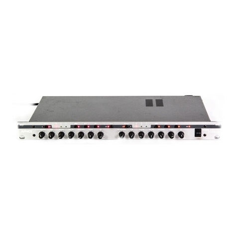
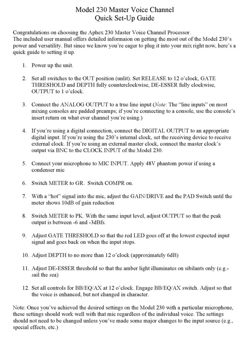
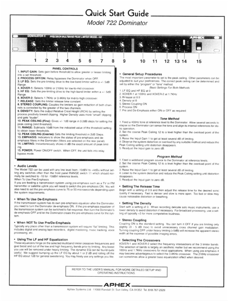
Aphex COMPELLOR 9301 User manual

www.SteamPoweredRadio.Com
COMPELLOR
MODEL
9301
OPERATING GUIDE
1.0 INTRODUCTION
The
Aphex
COMPELLOR
is
a multipurpose audio processor designed
to
give inaudible control
of
short and long-term average program dynamic range.
The
COMPELLOR
operates
to maintain a well-
controlled "average" audio level.
That
is
to say
that
the
program floor
is
'1ifted
",
so quiet signals
become more audible, while excessively loud signals are reduced in level.
The
extent
of
control by
the
COMPELLOR
is
adjustable by simple controls.
In
the
COMPELLOR,
the
functions
of
compression, leveling, and limiting are interwoven with an
intelligent control system
to
maintain all
three
dynamic functions simultaneously.
The
various dynamic
characteristics
of
an
audio signal are analyzed and
the
processing adjusted to minimize
the
audible
effects
of
gain control. This means
the
"squeezing"
or
"pumping" effects commonly attributed to signal
compressors are absent with
the
COMPELLOR,
even when a large
amount
of
control
is
used.
The
main attribute
of
the
COMPELLOR,
then,
is
that
it
is
"invisible" in
the
audio system
-you
will not
detect
its
presence.
TABLE
OF
CONTENTS 1
1.0 INTRODUCTION . . . . . . . . . . . . .
2.0 OPERATIONAL CHARACTERISTICS
3.0
COMPELWR
INSTALLATION . . . . . . . . 2
4.0 FRONTPANEL
.•••
5.0 SPECIF1CATIONS
.....•
6.0
BWCK
DIAGRAM
..........
.
7.0 SCHEMATIC DIAGRAMS
4
6
9
10
11
Your
COMPELLOR
was carefully packed al
the
factory, and the
container
was designed
to
protect
the
unit from rough handling.
Nevertheless,we
recommend
careful eJa1mination
of
the
shipping
carton
and its
contents
for
any
sign
of
physical damage which could have
occurred
in
transit.
If
damage is evident,
do
not
destroy
the
container
or
packing material. Immediately notify
the
carrier
of
a possible claim
for
damage.
Shippingclaims must
be
made
by
the consignee.
1.1
Limited
Warranty
AphexSystems,
Ltd.
warrants
to
the
original owner
that
the
Compellor
will be free from defects in
parts
and
labor
for a period
of
one
(1)
year from
the
date
of
purchase.
THE
ABOVE WARRANTY IS
IN
LIEU
OF
ANY
OTHER
WARRANTY,
WHETHER
EXPRESSED,
IMPLIED
OR
STATUTORY,
INCLUDING, BUT NOT
LIMITED
TO,
ANY
WARRANTY
OF
MERCHANTABILITY, FITNESS
FOR
ANY
PARTICULAR
PURPOSE,
OR
ANY WARRANTY ARISING
OUT
OF
ANY
PROPOSAL,
SPECIFICATION,
OR
SAMPLE. APHEX SYSTEMS SHALL NOT BE
LIABLE
FOR
INCIDENTAL
OR
CONSEQUENTIAL DAMAGES. APHEX SYSTEMS
NEITHER
ASSUMES
NOR
AUTHORIZES
ANY
PERSON
TO
ASSUME
FOR
IT
ANY
OTHER
LIABILITY
1.2
Service
Information
If
it
becomes
necessary
to
return
a
unit
for repair,
contact
Aphex
for
a
return
authoriration
number,
repack it in
the
original
carton
and
packing material,and insure
the
shipment.
If
a warranty
repair,
enclose a copy
of
proof
of
purchase
and
send package
to
:
APHEX
SYSTEMS,
LTD.
11068
Rand
all
Street
Sun Valley, CA 91352
PH:
(818) 767-2929
FAX
: (818) 767-2641
WARNING:
10
REDUCE
1llE
RISKS OFFIRE OR ELEC1RIC SHOCK,DO NOT
EXPOSE
1llIS
APPLIANCE
10
RAIN OR MOISTURE.
Copyright O 1991
by
Aphex Systems, LTD.
All
rights reserved.
All
Aphex productnames
are
trademarks
or
registered trademarks of
Aphex Sytems, LTD.
Other
brand
and
product names are trademarks
or
registered trademarks
of
their
respective holders.
9233htw
APHEX
SYSTEMS
Compel/orModel
9301
-
Page
1 I

www.SteamPoweredRadio.Com
2.0 OPERATIONAL CHARACTERISTICS
The
COMPELLOR
is
a unique combination
of
Compressor, Leveler, and
Peak
Limiter.
The
COMPELLOR
has
three
detector
circuits
that
control a single gain element (see Block
Diagram)
.
The very simple,high quality audio path provides extraordinarytransparency.
The
compression and
leveling sidechains are "intelligent," being program-controlled and interactive.
The
result
is
a very
simple, easy-to-use device
that
is
free
of
the
sonic effects
of
pumping, breathing, noise build-
up,
popping and hole punching.
Before proceeding further the
reader
should be aware
of
the
terms
that
are used
in
this manual.
'Leveling
"has
a high compression ratio and has slow attack and release times. "Compression"has low
compression ratios with faster time constants. Limiting has a high compression ratio with veryfast
attack time and fast release time.
It
is
important to note
that
the higher
the
ratio and
the
faster
the
time constants, the
greater
the
audible effect
of
gain control
on
the
audio.
The
Compellor combines these functions
in
a way to minimize
the
audible effects
of
gain reduction.
The
leveler provides a "platform" based
on
long-term average levels.
The
compressor, working from
this "platform" has to do less gain reduction and can more easilyhandle short-term level changes. A
PROCESS
BALANCE
control varies
the
ratio
of
compression to leveling.
The
high-speed
(1
microsec) limiter catches any dynamic overshoots.
The
limiter also allows
the
compressor action to
remain slow enough to maintain natural transient qualities
in
the
audio.
To illustrate
the
co-functioning
of
the
three
systems, imagine a sudden 20dB increase
in
signal level
above 0
VU.
The
limiter
will
catch
the
peak
and hold it until
the
compressor causes enough gain
reduction to pull the audio out
of
limiting.
The
leveler
will
then
pull
the
audio
out
of
the
increased
compression. This will
return
the
audio to
the
same "sound" as before
the
20dB increase in input.
The
COMPELLOR
's compression
detector
is
influenced
not
onlyby
the
RMS
level
of
the
audio,
but
also byprogram dynamics and wave complexity,
so
audio quality
is
greatly enhanced
over
simple
RMS
or
average responding processors. Transient sounds are preserved, pumping and breathing eliminated.
It has a "soft knee" compression characteristic, with the ratio varying from
1.1
to 1 at threshold (30dB
below nominal
0VU),
increasing to 3 to 1 at
0VU.
The
attack and release times are automatically
varied from 5 to 50 ms for attack and 200 to
lOOOms
for release.
The
leveling process provides a slow and smooth control over
the
program level platform.
It
has a
fairly high ratio (20 to
1)
with variable attack and release times to simulate
the
way
the
ear
perceives
loudness over long periods.
The
attack and release times vary from
preset
values
of
2.5s and 5s,
respectively.
The
circuit's most useful purpose
is
to maintain a consistent compression
depth,
and
therefore quality, regardless
of
the
long
term
program input level. Certain sources, such as public
address systems, can have extreme, quick level changes. Those sources require faster release times
on
the leveler and the speed
is
switchable from
the
front panel.
The
peak
limiter has a fixed threshold 12dB above nominal 0VU with an attack time
of
1 microsec and
release time
of
10
ms.
The
12dB ceiling was carefully chosen to allow maximum cooperation
between
the sidechains, providing natural sounding
peak
characteristics while maintaining a strong average
level. This ensures maximum drive level to following devices without fear
of
clipping, overmodulation,
or
tape saturation.
For
those situations
in
which
there
is
sufficient
headroom
or
the
Compellor
is
followed bya more sophisticated
peak
processor (e.g.- the Dominator)
the
limiter
is
defeatable from
the front panel.
2.1
Dynamic Verification Gate (DVG)
The
DVG
monitors short
term
and long term average levels, compares them, and impedes gain
changes when program dynamics might be sacrificed for arbitrarygain reduction.
The
DVG
also
prevents gain release during short-term program pauses which otherwise would cause "pumping"
or
'breathing" effects. Vocal material
is
especially benefited by this feature, sounding natural even when
Page
2 - Compel/orModel
9301

www.SteamPoweredRadio.Com
extremely compressed.
DVG
action
is
indicated by a front
panel
LED.
2.2
Dynamic Recovery Computer (DRC)
The
DR
C allows very rapid recoveryfrom gain reduction
under
certain complex wave conditions.
Signals
that
are high in
peak
amplitude
but
low in relative
power
cause
an
increase
in
the
compression
release
rate.
Unrequired
gain reduction
is
thus
inhibited,
preventing
loss
of
transient
wavefronts,
holes,etc. This contributes towards a
natural,
open
sound, even
during
heavy
compression.
2.3 SILENCE GATE
The
Silence
Gate
is
another
important
part
of
the
COMPELLOR
's
natural
sound.
Whenever
the
input falls
below
the
selected threshold,
the
Silence
Gate
"freezes"
the
COMPELLOR,
inhibiting
release
of
the
gain
reduction.
This eliminates noise swells and allows normal fade-outs.
When
the
program
resumes,
attack
is
improved
on
the
next signal
because
gain reduction
does
not
now
have to
go full range.
This
is
NOT
a "noise gate" which
mutes
all audio. Such action would actually cause
greater
problems,
for noise modulation
is
much
more
noticeable
than
the
noise itself.
The
Silence
Gate
simplyholds
everything constant -no signal, no change.
The
Silence
Gate
will
hold gain reduction release
indefinitely -for several
hours,
ifnecessary.
2.4
DRIVE Control
The
last circuit controlling
the
VCA
is
the
DRIVE
control.
Turning
the
front
panel
knob
counterclockwise
attenuates
the
VCA,
thus
reducing processing.
Turning
the
control clockwise
opens
up
the
VCA,
sending more signal to
the
output
and
the
detectors,
providing
more
processing.
2.5 1/0 Circuits
The
input and
output
circuits are transformerless, servo-balanced.
These
circuits allow
the
COMPELLOR
it to be interfaced with a wide range
of
audio systems.
The
COMPELLOR
can be
driven from balanced
or
unbalanced
sources, as if
it
had a bridging type input transformer.
The
common
mode
rejection
is
excellent and
RFI
filtering
is
employed.
The
nominal
operating
level
(0VU)
of
the
input and
output
circuit can be
set
by
jumpers
on
the
main
PC
board
for -lOdBv,
+4
and
+8dBm
levels. Since
the
COMPELLOR
operates
at
a constant internal
level,
the
input and
output
metering
automatically follows.
The
output
circuit
is
a
unique
active type which can be used like a
transformer
winding.
If
one
of
the
output
legs
is
grounded,
full voltage swing
is
transferred
to
the
opposite
leg
of
the
balanced
output
.
Gain
and drive are
thus
preserved for
unbalanced
loads.
2.6
VCA Circuit
The
VCA itself
is
the
Aphex
1001 Voltage Controlled
Attenuator.
This
component
is
the
world's
finest monolithic Class A audio control device. Its integrated construction
enables
absolute matching
between
the
transistors, resulting
in
almost
perfect
tracking
in
thermal
and gain characteristics.
2.7 Typical Applications
The
COMPELLOR
is
a useful tool for virtually any audio system.
It's
hard even to imagine a situation
where
the
sound system could
not
benefit from a
more
controlled dynamic
range.
There
has
been
so
much
attention
brought
to
the
newest increases
in
dynamic range with
the
onset
of
digital technology
that
some
ofus
may have lost sight
of
the
difference
between
maximum dynamic
range and usable dynamic range.
In
the
typical live sound application, for example,
there
is
in
reality a very small difference
between
the
Compel/orModel
9301
-
Page
3

www.SteamPoweredRadio.Com
maximum level available from the sound system (or the threshold
of
pain), and the ambient noise level
in
a club, concert hall
or
the like. The 80
or
90dB
of
dynamic range
so
sought after
is
completely
useless
in
such instances.
It
is
also useless if
it
cannot be transferred from a compact disc to a cassette.
Without a
COMPELLOR
in
the
audio chain,
)UU
have to decide between losing quiet signals into
the
noise
or
having distortion from overload on loud sounds.
Listeners actuallyprefer listening to reduced dynamic range material, as long as open,transient
qualities are maintained. The
COMPELLOR
is
designed to accomplish these goals, while remaining
quite invisible
in
the process.
3.0 COMPELLOR INSTALLATION
3.1
Physical Considerations
The
9301
Compellor
is
designed to fit into one slot
in
an Aphex9000 frame and dbx 900 series frames.
The thumbscrews(# 6-32) secure
the
module to the frame.
3.2 Electrical Considerations
3.2.1 Povver
The
9301
is
powered by +/-15V.
The
power
is
bussed to the unit on the backplane
of
both
the
Aphex
and the dbx racks.
The
+/-24V which appears
on
the dbx rack
will
not affect the 9301 in any
way.
NOTE: The 9301 consumes 250mA worst case. Compute the total power consumption
of
all modules
in
the rack to determine ifsufficient power
is
available from the power supply.
On the Aphexrack model 9000R the audio ground and chassis ground come out the
the
power screw
. terminal connector seperately(see figure 1). The terminal marked
~
may be jumpered to the
terminal marked ,+, to electricallyconnect
the
audio and chassis grounds together.
3.2.2 Edge ConnectorPin-out (see schematics)
&L
1
2
3
4
5
6
7
8
9
10
11
12
13
14
15
Page
4 -CompellorModel
9301
Description
No connection
No connection
Ground (Chassis)
Ground (Audio)
+15V
-15V
Ground
Process enable
Tally2
Tally 1
Ground
Input+
Input -
Output+
Output
-

www.SteamPoweredRadio.Com
3.2.3
Rear
Panel
Connections
(screw
terminals
on
rear
of
racks)
0
-2
4 0
A+
Input
high 0
A+
0 +24 0 A-
Input
low 0 A-
0 GND 0 7
Ground
0 7
0 +I5 0
8+
Output
high 0
8+
0
-I
5 0 8-
Output
low 0 8-
0
~
0 c+ Process
enable
0
Ct
0
rf,
0
C-
Ground
0
c-
0
~
Ground
0
~
0
D+
Tally 1 0
D+
0 D- Tally 2 0 D-
Fig: 1
Rear
Panel Connections
3.2.4
Operating Level
Set
The
Nominal operating level
of
the
9301 may
be
set for -lOdBV,
+4
or
+8dBm
via a
jumper
for
the
input and
output
located
on
the
main PCB.
The
appropriate position for each level
is
printed next to
each
jumper.
These
jumpers
must
be
set properlyand equally to avoid input overload
or
insufficient
input level to
generate
gain reduction.
3.2.5
Audio
Input
and
Output Connections
The
9301
maybe
driven balanced
or
unbalanced.
If
balanced 'high" should
be
connected
to
A+,'1ow"
connected to A- and shield connected to
Ground
.
If
unbalanced,
connect
'high"to
A+,
'1ow" to A-
and connect a
jumper
from A- to
Ground.
The
output
can drive
either
balanced
or
unbalanced loads.
Connect
B+ for
output
high and B- for
output
low.
Do
not
connect shield.
If
driving a known unbalanced load, connect a
jumper
from B- to
Ground.
3.2.6
Impedances
Some equipment
is
designed to drive a 600 n load.
If
the
9301
is
to
be
driven by such equipment
there
is
a
jumper
on
the
main board which inserts a 600 n termination. This termination
is
lifted
in
relay
bypass.
3.2.7
Relay
Bypass
The
relay bypass routes audio directly from
the
input terminals to
the
output
terminals. This state
occurs when
the
relay
is
de- energized, providing automatic
power
fail-safe bypass.
The
relay
is
energized
either
from
the
front panel '1N" switch
or
by
remote
control.
The
remote
will
operate
when
the
front panel switch
is
in
the
"out" position, otherwise
the
unit
is
permanently
in
the
"in"
state.
If
the
remote
is
in
the
"in"
position
the
front
panel
'1N" switch
cannot
bypass
the
unit.
The
remote
is
activated by contact closure between
Ground
(C-) and ''Process Enable" (C
+)
terminals.
To provide
remote
indication
of
the
bypass/operate condition a relay closure
between
terminals D +
and
D-
occurs when
the
unit
is
not
in
bypass.
CompellorModel 9301 -Page 5

www.SteamPoweredRadio.Com
4.0
FRONT
PANEL
4.1 METERING ~
APHEXe
9301
The
COMPELLOR
has a unique multi-function, bi-color bargraph
meter
that can be switched to monitor average and
peak
levels for input and
output,
as well as show
the
amount
of
gain reduction.
The
momentaryswitch
selects
INPUT,
OUTPUT,
or
GAIN
REDUCTION
metering.
For
INPUT
and
OUTPUT,
the
last
LED
of
the
red
bar
indicates average
level
(VU)
and
the
last
LED
of
the
green
bar
above
it
shows
peak
level.
Program dynamics and density can be seen at a glance.
The
scale
is
3dB
per
division and
is
on
the
right
of
the
LED's.
NOTE: Use
the
last
RED
LED
to determine correct nominal operating
level.
In
the
GAIN
REDUCTION
mode,
the
meter
shows
the
total amount
of
gain reduction as a green bar. A single red
LED
indicates
the
amount
of
leveling.
The
green
bar
portion
above
the
red
LED
indicates
the
amount
of
compression. Use
the
scale
on
the
left
of
the
LED's
(2dB division
per
LED)
to read
GAIN
REDUCTION.
For
example, if 16dB
of
total gain reduction
is
indicated and
the
red
LED
is
at l0dB, 6dB
of
compression above
10
dB
of
leveling
is
indicated.
The
yellow
'DVG"
LED
flashes
to
show
DVG
action whenever
the
computer control circuits have anticipated and prevented a "pumping"
occurrence.
A red
LED
flashes whenever
the
limiter
is
operating.
It
will
onlyflash if
the
'1..MT
ON"
switch
is
engaged.
I
COMeELLQB.,..
I
20
0
+12
0
11
o
..
[[2J]
11
0
..
IN
l4
0
-3
:~:C)
• 0 ..
laj
~
8
0 ..
DRIVE
4
0
-12
C)
2
Q-111
OVG
Q
LEVEL
car
IN
Q
PROCESS
BALANCE
;iC)
--
•10<8
OUTPUT
~[[2J]
0
;0C)
-
Od8
GATE
~NCE
4.2
IN Switch
The
IN
Switch provides a relay bypass for system in/out comparison. An
accompanying
LED
indicates red for IN.
Fig: 2 Compel/orFront
Panel
If
the
remote
control
of
the
bypass switch
is
used
the
IN/OUT
Switch must
be
in
the
"OUT"position.
The
LED
will
indicate
appropriate
status.
4.3 DRIVE Control
The
DRIVE
Control
sets
the
total
amount
of
gain reduction by controlling
the
amount
of
signal sent
to
the
detector
circuits.
Turning
this control clockwise provides more gain reduction.
4.4
LVL
SPD (LEVEL SPEED) Switch
This switches
the
release time for
the
leveler between "SLOW"
in
the
OUT
position and 'FAST"
in
the IN position. Use 'FAST" for speech and "SLOW" for general music programming.
4.5 PROCESS BALANCE Control
The
PROCESS
BALANCE
Control divides
the
audio between
the
compression and
the
leveling
sidechains,
thereby
controlling
the
ratio
of
leveling to compression. At
the
full counter-clockwise
position full leveling occurs, while full compression occurs at
the
full clockwise position.
Other
positions provide a mix
of
the
compression and leveling.
In normal
operation,
a mix
of
the
two
is
desired, so
that
there
is
always some leveling available to
absorb long term program level changes. This
will
ensure a more consistent amount
of
compression
Page 6 -Compel/orModel 9301

www.SteamPoweredRadio.Com
regardless
of
long
term
program level.Unlike conventional devices with a fixed threshold that increase
or
decrease compression as program varies,
the
COMPELLOR
will
not
change
the
sound quality.
4.6
OUTPUT
Control
The
OUTPUT
Control provides a ±
lOdB
variation
in
the final signal level from
the
Compellor. This
control
is
used to set unitygain at
output
after the gain reduction settings are made. This control may
also be used to raise
or
lower
the
output
level for
other
needs, as desired.
4.7
LMT
ON (LIMITER ON} Switch
This switches
the
Limiter
on
and off. In those situations which have sufficient headroom
or
which the
Compellor
is
followed by a more sophisticated
peak
processor such as the
Dominator,
the
limiter
in
the Compellor
is
unnecessary and should therefore be defeated.
If
the
switch
is
'1N"
and the Limiter
is
working a red
LED
above
the
switch
will
light.
4.8
SILENCE GATE Control
The
Silence
Gate
is
NOT
a "noise gate"
that
mutes the audio. Instead, it senses
that
the
audio has
dropped below your
pre-
determined level and directs
the
Compellor to "freeze", preventing any
release
of
gain reduction. This eliminates noise build-up common to
other
compressors
or
AGC
devices which occurs during pauses
in
program.
The
Silence
Gate
also permits fade- outs,
so
the AGC
is
not
fighting you as you try to lower
the
output
level.
The
SILENCE
GATE
Control lets you set the Silence
Gate
threshold from Oto -40dB, relative to
your operating level (0VU). Since
it
inhibits any action by
the
COMPELLOR,
it should never come
on during normal program material.
The
proper
threshold level should be somewhere between the
lowest level program signal and
the
noise floor
of
the system before
the
Compellor.
It
should activate
(after about 1second delay) when audio stops
or
gets part way into a fade. Silence
Gate
action
will
be
indicated by
the
yellow
LED
above
the
knob.
4.9
INITIAL SETTINGS
After
the
COMPELLOR
has
been
properly installed perform
the
following steps to familiarize
yourself with its operation.
Switch
'1N":
METER
SELECT:
Stat.us.
OUT
INPUT
With no audio present, notice that the Silence
Gate
THRESHOLD
LED
will
be lit
(YELLOW),
and
that
the
meter's bargraph
LEDs
are not lit.
LEVELING
SPEED
should be
"Slow"
(out position)
Connect
either
a test
tone
or
an audio program to
the
COMPELLOR
's input, and verify
that
the
meter
indication on
the
COMPELLOR
match
the
output
of
the device feeding
the
input. At this
point, you should also see
the
(Silence
Gate)
THRESHOLD
LED
extinguish whenever program level
exceeds
the
initial
THRESHOLD
setting.
NOTE:
If
you see
other
than unity level at
the
output,
the
COMPELLOR
may need its nominal
operating level changed
or
installation
of
termination resistors.
With
the
PROCESS
BALANCE
set for 50/50 mix (12 o'clock position)
of
compression and leveling,
select
GAIN
REDUCTION
on
the
METER
SELECT
Switch and adjust
the
DRIVE
Control to
achieve
the
desired amount
of
total gain reduction.With the
DRIVE
set at 3 o'clock
there
will
be
around l0dB
of
total gain reduction,
of
which 4 to 6dB
is
compression.
Don't
be afraid to use more!
The
Compellor
is
Sil
transparent
in
its action that you can use
greater
amounts
of
gain reduction
without affecting program quality.
The
leveling action cannot be heard at all,
so
you can easily use
Compel/orModel
9301
-
Page
7

www.SteamPoweredRadio.Com
lOdB
oflevelingto handle broad program level changes.
NOTE:
The
amount
of
gain reduction generated with the input at nominal level
will
determine how
much the lowest level signal
will
be increased.
For
example, if 16dB
of
gain reduction
is
generated with
"0'VU input and
the
gain reduction
is
released when a low level signal is present,
the
Compellor
will
have brought that low level signal up 16dB.
NOTE:
If
the
DRIVE
Control
is
at
OdB
(full
CW),
and more gain reduction
is
needed,
either
increase
the
input level to
the
COMPELLOR
or
readjust the
OPERATING
LEVEL
switch
on
the
main audio board to a lower setting.
NOTE:
The
PROCESS
BALANCE
Control, along with Drive, determines
the
"tightness"
of
the
output. More Leveling gives a more "open" sound.
More
Compression (along with more total gain
reduction) gives a "tighter" sound.
NOTE:
In
live applications
the
total amount
of
gain reduction may
be
determined by
how
much gain
before feedback
is
in the system. Caution
is
advised therefore when using large amounts
of
gain
reduction
on
open
microphones.
Select
OUTPUT
on
the
METER
SELECT
Switch and set
the
OUTPUT
Control to attain unitygain
with 0VU input.
Depending
upon
the
"tightness"
of
the
dynamic range as set by
the
DRIVE
and
PROCESS
BALANCE
controls,
the
long
term
average
output
of
the
COMPELLOR
will
remain
close to the nominal
operating
level.
As you observe
the
audio program, set
the
Silence
Gate
THRESHOLD,
so
that
the
Silence
Gate
comes
on
(yellow
LED)
after
the
lowest audio levels (including fade-outs), yet still above
the
input
noise floor.
An initial setting for
the
Silence
Gate
THRESHOLD
is
-20dB (12 o'clock position).
The
Silence
Gate
LED
should come
on
about 1second after audio stops,
or
is
partly into a fade-out. A little
experimentation
will
easily give you
the
right adjustment area.
NOTE: Be sure to verify
that
the
Silence
Gate
does not come
on
during normal program, as this will
inhibit
proper
action
of
the
COMPELLOR.
After you are satisfied with
the
settings these steps, press the '1N" Switch to indicate IN
(Red
LED)
so
that
the
COMPELLOR
is
on-
line.
Readjust
the
COMPELLOR
Controls to achieve
the
desired "tightness" and
output
level as necessary.
Experiment with
the
PROCESS
BALANCE
Control turned more towards
LEVEL
than
COMPRESS.
NOTE:
The
leveler, having a fixed ratio, maintains a "platform"for
the
compressor, byholding a
constant amount
of
a compression regardless
of
input level changes. This "platform" will maintain
the
same "sound," regardless
of
program level. As you turn the
PROCESS
BALANCE
knob (CCW)
toward leveling, you will notice
that
the
instantaneous dynamic range becomes less controlled. As
the
PROCESS
BALANCE
Control
is
moved clockwise
there
will
be more Compression and
the
sound
will
become "fatter".
If
the leveler
is
used without any compression at all (full CCW),
there
is
the
possibility
of
some
'breathing"
or
"swelling" with large level changes, due to the very slow attack and release. Also,
the
Leveling Speed switch may be set to suit
either
speech(fast)
or
music(slow) programs.
You easily can compare
the
sound
of
the
audio signal with and without
the
COMPELLOR.
When
you
press
the
'1N" Switch to
the
"out" position, a hardwire bypass will be inserted into
the
audio
path.
Page
8-Compel/orModel
9301

www.SteamPoweredRadio.Com
5.0 SPECIFICATIONS
INPUT SPECIFICATIONS
Type:
Impedance:
Nominal
Operating
Level:
CMRR:
SIDECHAIN SPECIFICATIONS
Compression
Attack
Time:
Release
Time:
Ratio:
Threshold:
Leveling
Attack
Time:
Release
Time:
Threshold:
Peak Limiter
Attack
Time:
Release
Time:
Threshold:
OTHER SPECIFICATIONS
Power
requirements:
Weight:
Transformerless
,
RF-filtered
,
true-instrumentation,
differential
servo-balanced
50kn
balanced
User
Selectable
0VU
=
-lOdBv,
+4
or+
8dBm
Maximum
Input
Level:
+27dBm
Greater
than
60dB,
20Hz
to
lOkHz
5
to
50ms
200ms to
ls,
program
dependent
1:
1to 30:1
30dB
below
nominal level
(0VU
with
DRIVE
full clockwise)
ls/2.Ss (switch selectable)
2s/5s (switch selectable)
program
dependent
30 dB
below
nominal level
(0VU
with
DRIVE
full clockwise)
lµs
200ms
12dB above nominal level
(0VU)
+/-15 Volts
DC,
250mA
2lbs
Compel/orModel 9301 -Page 9

www.SteamPoweredRadio.Com
.,
., ,.,
~
~
(1:,
......
C
I
MODEL
9 3 0 1 MODULAR COMPEL
LOR
BLOCK DIAGRAM
g
~
(1:,
~
cS"
"'I
f
(1:,
INPUT
REF
SELECT
~
~
I
INPUT
OUTPUT
~
+
SER
V0
OUTPUT
SERVO
BALANCED
APHEX
OUTPUT
BALANCED
a,
INPUT
VCA l OO l
REF
OUTPUT
.
STAGE
V
CA
t t
SELECT
STAGE
0
c,:J
IN
RELAY
~
r-
CONTROL
0
C')
REMOTE
;;;s:::
SILENCE
I I I I 0
&ATE
SILENCE
LEO
c=::J
-
&ATE
)>
DETECTOR
C)
lJ
-
LED
I I
ELECT.
AV 6
)>
p
E
AK
II
SWITCH
DRIVE
~
DETECTOR
I'--..
ELECT.
PEAK
SWITCH
DRIVE
COMPRESSION
SIOECHAIN
I
BICOLOR
LED
PROCESS
DISPLAY
BALANCE
ELECT.
COMP.
LEVEL
IN&
SWITCH
DRIVE
SIDECHAIN
I
ELECT.
I I
LEVEL
DY&
DRIVE
SIi
ITCH
DR
I
YE
LE 0
LVL
SPO

www.SteamPoweredRadio.Com
g
~
~
~
~
~
-
~
~
I
?
......
.....
AUDIO
OUT+
14
AUO
IO
OUT-
15
JP4
C61
RIil
.01UF"
L2
101(
1000UM
AUDIO
IN-
13
AUDIO
IN+
12
AUDIO
CNO
l1
PO'-NER ONO 4
+15
POWER
5
-15
POWER &
VRO
H</1T
-••
R102
11(00
:::2~
;~~~
R94
Rlil5
10KO 10KO
~
.,.
I~
r~·
100K
470PF
i
C33
1183
C32
T•7oPr
100K
470Pf'
•••
LS
10IC
flU!14
2i6'.JH
1000UH
11(00
+~
1
u1a
+ 12
TP2
+
CCII
B
..,....
luf
R90
VRS
"7
39"2
100/H
+15
I
~
•••
41(99
w
..
,
41(99
w
C38
20H
.
3~~~•.,.
3m
1
~
~~~
+
- 15
BALANCE>
VR4
10K/'1T
.~,1
u
..
,,,
I
101(
CMRR
,.,.,
..
;1-
50K/1T
,.,oo
,.,oa
1
01(
..
,.
C11
......
20,.1
,.,.
""'
101(0
101CO
flt2
101CO
-'VV'-
=-21(
20.1
~1(20.1
R12
101(0
~~··
fl87
41("
... ,
,.ea
1etC2
-<>
e>
_,
0
C38
20P'
tTA
U12
NEM
aN.
R13
3321<
1-7
....
10U
c•o
10pl
+15
riio
100uf
cu
u11,
~lr353
•••
,
5&R2
-15
1120
1
()1(0
Ht-:~ _-
,5
R35
11(00
Hl-1
R37
C10
101<0
.
01u1
-15~
R38
R3&
"'°"
1UOO
..
I
<-15
03
1N814,8
Q3
2"-1390-4
.!j
...
1()1(0
01
~
2N39otl
1'
C14
~ .Oh.11
-
Cl
.
3.lY
f
Rl
10M
"33
341<0
t--------,---w-,
- ,g
....
101(0
~
R27
904"
1/2W
JP3
800
OMM
OUTPUT
9ALANC£
TPI
R22
201<0
+1
.
!,
,..,
113R
!..
ca
¢100UF
10
TAL
L Y 2
9
TALLY
1
a
PROC
ENB
7
CN0
3
CHASS
IS
s-
fo----;
IN
LOCAL
BYPASS
CAPS
Hl-t
'I
I _l
I.,
...
c,u.
C53
C&
•
C21
~
HI-~::•
•I
·
'"'
I
100u1
I
100uf
I
C45
C52
C41
•
C22
+
-&
.
1uf
I
.tuf
I
100uf
I
100vf
I
Ht-!.
C3
t
~15
APH[,c
S'T'SlD•S
L
TO
.
WOOEL
9301
COMPCLLOR AUOK>
PCB
ocument
Jlritum~
68-19581.SCH
,rowr1
l!!ly
0 R LKlEN
-
EV
e
...J
.
0
en
n
:::c:
m
s:
)>
-I
-
n
en

www.SteamPoweredRadio.Com
.,
.,
~
~
......
N
i~~f
11170
R71
iN~~!e
,Ni~~
R77
1145
I
~
•
11'2R
lOOI<
1KOO
H(OO
a
¢'
~
C
D11
LED
10KO
;!
1N9149
+15r--W
'°G
A
t----1-----.
fu
2
l'
r•
;~~
L018
LD.l
~
SIL£...,CE
CllrEEN
L[O
OA[EN
LED
:::::
GATE
R72
'-
C
""'o
,oOK
""'t
15C10K
~
CW
C.
J:178
,-----(>Hl-14
~
100R
+1!1
~
,:q
~
c,a
0
0,
c::,
'"*
i....;;,.
10te0
101<0
".,..._....,_...,,..,,...
__
.
..
..
IU
7
+
15
r
04
5H(1
U7A
L,-353
C63
1N8148
10Df
~lltOCESS
~
8ALANCE
C2a
H7
I
1119.
e
~
d9.,,.
1
JC-~
1 5
Sk25
20KO
=~
-
1
+15
•
15
~
~
t
L
UOA
I
4
C16
,..,
IOOIC
1(lpf
OUTPUT
cw
R38
"""
101(0
8101(
R&O
11(00
C
VR3
21<5/1T
I
RH
100K
RY
151(0
llt57
"""
""'"'
1"67
1001(
10KO
2
017
,---'V'V"-.-----i•--+-----.J\,"-"~t--'V".,,._~--O-H1-12
I
.,~
I
o,e
L02
GREEN LEO
''
011
1N0141!1
.....
33'<0
010
Hr,t9149
t-----0-Hl-
11
0111\IE
VR7
8101<
~
f '
D
tt1-10
+1?.
+1
.5
R58
!KOO
""'
501C/1T~
"""
!KOO
~H
1-1
3
CW
-15
...
.!.
C2.l
¢
22uf
APH[X
SVSlt:MS
L TO•
,.,
MOOEL
8301
COMPEUOR
AU~O
PCS
,,
..
8
[V
8

www.SteamPoweredRadio.Com
g
-§
~
§=
..,
~
~
-
~
~
I
~
~
......
~
A220
22K,
U20.5A
C04011
H201-
2
~
M201
- 7
~
e
SW2O3
LEVE
LINC
RATE
SW20
1
~J
i~~l
~~
11243
11244
11231
112~.
C208
¢
10t<O
101(0
4Klil8
,c!c~
I
~!':8
R234
LIMIT
SW202
;;;;
;¢+
15
lM00
19148
_
+
+1
,
!>
4
R20.5
4K70
R204
41(70
-15
0220
1Jilil9148
+1!>
♦
1,5
' t
R21S
100K
C203
.....1....
C21.5
i ,
lyf
¢ .
1uf
Ft245
""""
LEVELINC
DC
C2O9
20pf
"239
101<0
+15
~~
u~t~4
~--
-
-r
R2:~!I
'-,
1()1(0
A
~
000
~
fil:
c;--
--
~
c;-
---
?
H201-9
I
H201-16
-15
U209A
lJ.l.53
H201-12
~
+15
flt213
""'g
Ft214
,.,5
..
2,2
11(00
C211
¢
1uf
+15
COMPRESSIQtr,,I
DC
0204
1H914B
R2~1
10 0
1(
H20
1
-i
◄
<J
ti
...,,...,,
"'"tli
_,.
+15
H201-1
<I
II
II"
I
LMT
Tltle
a
~1~
1
C212
1
C21.3
:J:
10<>,f
¢
100uf
.APMEX
SVSTElriAS LTO
a.AOOEL
9301
COMPELLOR
DISPLAY
PCB
oc:ument
Numb•r
raWn
·
By
l1'£V
&e-,u&B
.
SCH
C R LI
OEN
9
ct
1
eet
-
L0202
RED
LED
A<I
''14
L0203
RED LEO
e-
....
CQ
•••
I
R218
11(00
+,
.5
'c---W----"
INPUT
OUTPUT
C.R.
R224
21(00
R22&
11(18
Ft229
R227
201<0
U2098
LF3.53
M201-10
~
H201-13
~H
l.:228
101(0
-
201-•
+15
c20,
J.
.1Uf'"
¢
-15
C202_l_
.
1UF
¢
+1"
.,..,.
•
Table of contents
Other Aphex Computer Hardware manuals