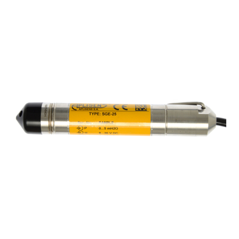
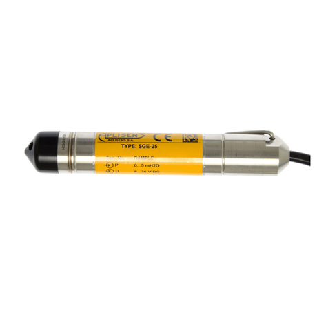
Aplisens SGE-25.Modbus User manual

USER’S MANUAL
SMART LEVEL PROBES
SGE-25.Modbus and SGE-25S.Modbus
EN.IO.SGE.25.MODBUS
DECEMBER 2022
APLISENS S.A., 03-192 Warsaw, Morelowa 7 St
tel. +48 22 814 07 77; fax +48 22 814 07 78
www.aplisens.com, e-mail: [email protected]
Revision 02.A.001

PRODUCT CODE –see: (➔Probe identification).
The QR code or ID number identifies the probe and provides quick access to the following documentation on the
manufacturer’s website: User’s Manual, Explosion Proof Device Manual, Modbus Manual, declarations of con-
formity and copies of certificates.
SGE-25.Modbus
ID: 0044 0001 0001 0000 0000 0000 0001 77
https://www.aplisens.pl/ID/004400010001000000000000000177/
SGE-25.Modbus (Exi)
ID: 0044 0002 0001 0000 0000 0001 0001 94
https://www.aplisens.pl/ID/004400020001000000000001000194/
SGE-25S.Modbus
ID: 0045 0001 0001 0000 0000 0000 0001 74
https://www.aplisens.pl/ID/004500010001000000000000000174/
SGE-25S.Modbus (Exi)
ID: 0045 0002 0001 0000 0000 0001 0001 91
https://www.aplisens.pl/ID/004500020001000000000001000191/

Symbols used
Symbol
Description
Warning to proceed strictly in accordance with the information contained in the
documentation in order to ensure the safety and full functionality of the device
Information particularly useful during installation and operation of the device.
Information particularly useful during installation and operation of an Ex type device.
Information on disposal of used equipment.
BASIC REQUIREMENTS AND SAFE USE
The manufacturer will not be liable for damage resulting from incorrect installation,
failure to maintain a suitable technical condition of the device or use of the device
other than for its intended purpose.
Installation should be carried out by qualified staff having the required authorizations
to install electrical and I&C equipment. The installer is responsible for performing
the installation in accordance with manual as well as with the electromagnetic com-
patibility and safety regulations and standards applicable to the type of installation.
In systems with I&C equipment, in case of leakage, there is a danger to staff due to
the medium under pressure. All safety and protection requirements must be ob-
served during installation, operation and inspections.
If a malfunction occurs, the device should be disconnected and handed over to the
manufacturer for repair.
In order to minimize the risk of malfunction and associated risks to staff, the device
is not to be installed or used in particularly unfavorable conditions, where the follow-
ing hazards occur:
−possible mechanical impacts, excessive shocks and vibration;
−excessive temperature fluctuation;
−water vapor condensation, dusting, icing.
Installations for intrinsically safe executions should be carried out with particular
care in accordance with the standards and regulations applicable to this type of
installation.
Changes made to the manufacturing of products may be introduced before the paper version of the
manual is updated. The up-to-date manuals are available on the manufacturer’s website:
www.aplisens.com.

EN.IO.SGE.25.MODBUS
4Revision 02.A.001/2022.12
TABLE OF CONTENTS
1. INTRODUCTION...............................................................................................................7
1.1. Purpose of the document .......................................................................................................7
2. SAFETY............................................................................................................................7
3. TRANSPORT AND STORAGE.........................................................................................8
3.1. Delivery check........................................................................................................................8
3.2. Transport................................................................................................................................8
3.3. Storage and use.....................................................................................................................8
4. GUARANTEE....................................................................................................................8
5. IDENTIFICATION..............................................................................................................9
5.1. Manufacturer address ............................................................................................................9
5.2. Probe identification.................................................................................................................9
5.3. CE mark, declaration of conformity.........................................................................................9
6. INSTALLATION..............................................................................................................10
6.1. General recommendation.....................................................................................................10
7. ELECTRICAL CONNECTION.........................................................................................11
7.1. Connection, signal output.....................................................................................................11
7.2. Power supply........................................................................................................................12
7.2.1. Power supply voltage....................................................................................................12
7.2.2. Resistance load in power supply line............................................................................12
7.3. Equipment bonding ..............................................................................................................13
7.4. Overvoltage protection.........................................................................................................13
7.5. Final inspection of cabling....................................................................................................13
8. OPERATION...................................................................................................................13
8.1. Physical layer for RS485 data transfer .................................................................................13
8.1.1. Introduction...................................................................................................................13
8.1.2. Description....................................................................................................................13
8.1.3. Details of RS485 “half duplex” ......................................................................................14
8.1.3.1. Limited digital signal incremental rate....................................................................14
8.1.3.2. “Fail safe” mode.....................................................................................................14
8.1.3.3. 1/16 of bus load.....................................................................................................14
8.1.3.4. Line transmission...................................................................................................14
8.1.3.5. Polarizing resistors ................................................................................................15
8.1.3.6. Common mode voltage on RS485 bus ..................................................................15
8.2. Data link layer ......................................................................................................................15
8.2.1. Modbus RTU serial transmission mode ........................................................................16
8.2.2. Modbus RTU message format......................................................................................16
8.2.3. Modbus RTU message transfer rules............................................................................17
8.2.3.1. Primary rules .........................................................................................................17
8.2.3.2. Error handling........................................................................................................18
8.3. Application layer, description of implemented functions........................................................18
8.3.1. System functions ..........................................................................................................18
8.3.1.1. 0x03 (3) “Read Holding Register” ..........................................................................18
8.3.1.2. 0x2B (43) ”Read Device Identification”...................................................................19
8.3.2. Manufacturer/user functions..........................................................................................19
8.3.2.1. 0x64 (100) „Read coefficients”...............................................................................19
8.3.2.2. 0x65 (101) „Write coefficients” ...............................................................................21
8.3.2.3. 0x66 (102) „Set Modbus Device Address (FLASH)”...............................................21
8.3.2.4. 0x67 (103) „Set Speed, Parity, Stop” .....................................................................21
8.3.2.5. 0x68 (104) „Perform Action”...................................................................................22
8.3.2.6. 0x69 (105) „Set Modbus Device Address (RAM)” ..................................................22
8.3.3. Modbus register layout..................................................................................................23
8.3.3.1. Request message with the function 0x03 (Example 1)...........................................24

EN.IO.SGE.25.MODBUS
Revision 02.A.001/2022.12 5
8.3.3.2. Request message (Example 2) .............................................................................24
8.3.3.3. Received data based on example 2, assigned to the relevant registers.................25
8.3.4. Data from registers readable using function 03 ............................................................25
8.3.4.1. Register 1, user value, % control of the set range.................................................25
8.3.4.2. Register 3, pressure of sensor 1 ...........................................................................25
8.3.4.3. Register 5, pressure of sensor 2 ...........................................................................26
8.3.4.4. Register 7, temperature of sensor 1......................................................................26
8.3.4.5. Register 9, CPU temperature................................................................................26
8.3.4.6. Register 11, temperature of sensor 2....................................................................26
8.3.4.7. Register 13, standby .............................................................................................26
8.3.4.8. Register 15, standby .............................................................................................26
8.3.4.9. Register 17, user value .........................................................................................26
8.3.4.10. Register 18, pressure of sensor 1 –binary format, integer and sign......................26
8.3.4.11. Register 19, pressure of sensor 2..........................................................................27
8.3.4.12. Register 20, temperature of sensor 2 –binary format, integer and sign.................27
8.3.4.13. Register 21, CPU temperature –binary format, integer and sign...........................27
8.3.4.14. Register 22, temperature of sensor 2....................................................................27
8.3.4.15. Register 23, pressure unit .....................................................................................27
8.3.4.16. Register 24, standby .............................................................................................27
8.3.4.17. Register 25, standby .............................................................................................28
8.3.4.18. Register 27, standby .............................................................................................28
8.3.4.19. Register 29, standby .............................................................................................28
8.3.4.20. Register 31, response dalay value ........................................................................28
8.3.4.21. Register 32, Modbus address................................................................................28
8.3.4.22. Register 33, identity register..................................................................................28
8.3.4.23. Register 36, status register....................................................................................28
8.4. Configuration mode .............................................................................................................29
8.4.1. “Modbus Configurator” software. Serial port configuration, Modbus network scanning,
single transmitter search............................................................................................................29
8.4.2. Device identification data..............................................................................................32
8.4.3. Reading the transmitter’s limit values process variables...............................................33
8.4.4. Reading alphanumeric identification data.....................................................................33
8.4.5. Damping and transfer function .....................................................................................34
8.4.6. Modbus mode ..............................................................................................................34
8.4.7. Restore default settings................................................................................................34
8.4.8. Write lock.....................................................................................................................35
8.4.9. Additional operation......................................................................................................35
8.4.10. Calbrations...................................................................................................................35
8.4.10.1. Level calibration....................................................................................................35
8.4.10.2. Calibrating the analogue output.............................................................................36
8.4.10.3. Setting the fixed current mode...............................................................................36
8.4.10.4. Configuration write................................................................................................36
8.5. Current loop 4-20 mA operation...........................................................................................36
8.5.1. Alarm signal levels .......................................................................................................37
8.6. Modbus mode......................................................................................................................37
9. MAINTENANCE..............................................................................................................38
9.1. Periodic inspections.............................................................................................................38
9.1.1. External overview.........................................................................................................38
9.1.2. „Zero” check.................................................................................................................38
9.2. Non periodic inspections......................................................................................................38
9.3. Cleaning/Washing................................................................................................................38
9.4. Diaphragm cleaning.............................................................................................................38
9.5. Spare parts..........................................................................................................................38
9.6. Repair..................................................................................................................................38
9.7. Return..................................................................................................................................38


EN.IO.SGE.25.MODBUS
6Revision 02.A.001/2022.12
10. SCRAPPING, DISPOSAL...............................................................................................39
11. HISTORY OF REVISIONS..............................................................................................39
11.1. PCB and software versions..................................................................................................39
Appendix 1. Explosion-proof Device Manual EN.IX.SGE.25.MODBUS............................41
LIST OF DRAWINGS
Figure 1 Mounting brackets for probes..............................................................................................10
Figure 2 Diaphragm cover for SGE-25S.Modbus probe ....................................................................10
Figure 3 Connection in Modbus network...........................................................................................11
Figure 4 Example of Modbus network configuration..........................................................................14
Figure 5 Set range and measurement limits......................................................................................36
LIST OF TABLES
Table 1 Symbols appearing on the probe’s nameplate ........................................................................9
Table 2 Probe connection..................................................................................................................12
Table 3 Permissible power supply voltage for probes........................................................................12
Table 4 Set range and measurement limits........................................................................................37

EN.IO.SGE.25.MODBUS
Revision 02.A.001/2022.12 7
1. INTRODUCTION
1.1. Purpose of the document
The subject of manual are smart level probes: SGE-25.Modbus and SGE-25S.Modbus hereinafter
referred to as probes in the manual. The manual applies to the following versions: standard and intrin-
sically safe Exi.
The manual contains data, guidelines and general recommendations for the safe installation and oper-
ation of the probes, as well as procedures in the event of a possible failure.
It is forbidden to use devices in hazardous areas without appropriate permits.
Data on the hydrostatic level probes SGE-25.Modbus, SGE-25S.Modbus and
SGE-25C.Modbus in intrinsically safe version according to ATEX are included in the
Explosion-proof Device Manual marked as EN.IX.SGE.25.MODBUS.
2. SAFETY
−The installation and start-up of the device and anyactivities relatedto operation shall
be carried out after thorough examination of the contents of user’s manual and the
instructions related thereto;
−installation and maintenance should be carried out by qualified staff having
the required authorizations to install electrical and measuring devices;
−the device shall be used according to its intendedpurpose in line with the permissible
parameters specified on the nameplate (➔Probe identification);
−the protection elements used by the manufacturer to ensure probes safety may
be less effective if the device is operated in a manner not consistent with its intended
purpose;
−before installing or disassembling the device, it is absolutely necessary
to disconnect; it from the power source;
−no repairs or alterations to the probes electronic system are permitted. Assessment
of damages and possible repair may only be performed by the manufacturer
or authorized representative;
−do not use instruments if damaged. In case of malfunction, the device must be put
out of operation.

EN.IO.SGE.25.MODBUS
8Revision 02.A.001/2022.12
3. TRANSPORT AND STORAGE
3.1. Delivery check
After receiving the delivery, please refer to the general terms and conditions of contracts available
on the manufacturer website:
https://aplisens.com/ogolne_warunki_umow.html.
3.2. Transport
Transport of probes shall be carried out with the use of covered means of transport, in original packages
with diaphragm provided with protection. The packaging shall be protected against movement
and direct impact of atmospheric factors.
3.3. Storage and use
Probes shall be stored in a factory packaging, in a room without vapours and aggressive substances,
protected against mechanical impact. The cable should be coiled into a circle with a diameter
of ≥ 30 cm, the coils of the coil should be fixed in relation to each other and the whole should be fixed
in the package. Avoid kinking the cable at the point where it exits the gland.
Permissible medium temperature range according to the data sheet.
The medium must not be allowed to freeze in the immediate vicinity of the probe.
4. GUARANTEE
General terms and conditions of guarantee are available on the manufacturer's website:
www.aplisens.com/ogolne_warunki_gwarancji.
The guarantee shall be repealed if the device is used against its intended use, failure
to comply with user’s manual or interference with the structure of the device.

EN.IO.SGE.25.MODBUS
Revision 02.A.001/2022.12 9
5. IDENTIFICATION
5.1. Manufacturer address
APLISENS S.A.
03-192 Warsaw
Morelowa 7 St.
Poland
5.2. Probe identification
Depending on the version of the probe, the nameplates may differ in the amount of information
and parameters.
Table 1 Symbols appearing on the probe’s nameplate
5.3. CE mark, declaration of conformity
The device has been designed to meet the highest safety standards, has been tested and has left
the factory in a condition that is safe for operation. The device complies with the applicable standards
and regulations listed in the EU Declaration of Conformity and has CE marking on nameplate.
Logo and name of manufacturer
CE mark
CE mark with number notified body
Manufacturer address
QR code
Probe type
Probe model ID
Probe serial number
Measuring range
Power supply voltage
Output signal
Permissible range of ambient temperature
IP protection rating
Year of production
Note about the obligation of read the manual
//Lower part of
the nameplate//
Special versions

EN.IO.SGE.25.MODBUS
10 Revision 02.A.001/2022.12
6. INSTALLATION
6.1. General recommendation
The probe can be hung on the power cable, e.g. by using from the Aplisens SG cable hanger (item 1
in fig. 1). In the event of frequent removal of the probe or when there is a risk of catching on protruding
elements during pulling up, it is recommended to hang the probe on a steel cord using the carrying eye
(item 2 in Fig. 1.). The probes are immersed in the medium to be measured. A special cable extends
above the level of the medium and can be connected directly to probe or to a junction box. If the probe
is to be placed in the current or in an area of turbulence, it should be installed in a protective tube.
Figure 1 Mounting brackets for probes
Do not clean or touch the diaphragm with hard or sharp objects. Hang the probe with the additional
Teflon coating on the cable on the suspension cable or on the inner cable (do not grab the Teflon).
Remove the protective cap from the probe's separator immediately before
the SGE-25S.Modbus type probe is inserted into the medium to be measured.
During installation protect the probe from mechanical impacts
Figure 2 Diaphragm cover for SGE-25S.Modbus probe

EN.IO.SGE.25.MODBUS
Revision 02.A.001/2022.12 11
7. ELECTRICAL CONNECTION
7.1. Connection, signal output
All connection and installation operations shall be performed with disconnected supply volt-
age and other external voltages, if used.
I Failure to provide proper connection of the transmitter may result in danger.
Risk of electric shock and/or ignition in potentially explosive atmospheres.
Figure 3 Connection in Modbus network

EN.IO.SGE.25.MODBUS
12 Revision 02.A.001/2022.12
The electrical connection should be made according to Table. 2. It is recommended to install
the PP-Modbus connection box manufactured by Aplisens S.A. to connect the probe cable with the rest
of the transmission line. The PP-Modbus junction box is non-hermetic (pressure inside is equal to
atmospheric pressure) due to the use of an air filter, which is required for the probe to operate correctly.
Do not allow the capillary outlet to become contaminated or any liquid to enter the capillary.
Table 2 Probe connection
Signal output
Type of connector
Wire colour
SHIELD
Green
+
Red
- (GND)
Black
RS-485 A +
Blue
RS-485 B -
Yellow
7.2. Power supply
7.2.1.Power supply voltage
Supply cables may be live.
There is a risk of electric shock and/or explosion.
Installation in potentially explosive atmospheres must comply with local standards
and regulations.
Table 3 Permissible power supply voltage for probes
Mode
Output signal
MIN. Power supply
voltage
MAX Power supply
voltage
Modbus mode - standard version*
Modbus RTU
4 V DC
28 V DC
Modbus mode Exi version
Modbus RTU
4 V DC
10 V DC
Configuration mode –standard
version
4…20 mA
5 V DC
28 V DC
*- power consumption in Modbus mode <3,6 mA.
7.2.2.Resistance load in power supply line
The power line resistance, power source resistance and other additional serial resistances increase the
voltage drops between the power source and the transmitter. The maximum current is 0,022 A. The
maximum resistance value in the power circuit (along with the power cables resistance) is defined by
the formula:
where:
Uzas –voltage at the supply terminals of 4…20 mA current loop [V],
Umin –minimum supply voltage of probes Table 3 Permissible power supply voltage for probes,
RL_MAX –maximum power supply line resistance [Ω].

EN.IO.SGE.25.MODBUS
Revision 02.A.001/2022.12 13
7.3. Equipment bonding
The cable shield (green wire) is led out from the probe's power supply and measurement cable. The
manufacturer recommends connecting the probe cable shield at one end to the probe’s power supply
point.
7.4. Overvoltage protection
Probes may be exposed to the effect of switching overvoltage’s or those resulting from lightning dis-
charges. Protection against overvoltage’s between the wires of the transmission line is provided by TVS
diodes. For protection against surges between the transmission line and earth or housing (which are
not protected by diodes connected between the line conductors), the probes are equipped with addi-
tional protection in the form of surge arrestors. Additionally, an external protective device can be used,
e.g. the UZ-2 system by APLISENS or others.
7.5. Final inspection of cabling
After completing the electrical installation of the probe, check the following:
- that the supply voltage measured at the power supply terminals of the cable connection at the
maximum current is in accordance with the supply voltage range specified on the nameplate;
- that the probe is connected in accordance with the information given in section ➔7.1 Connection,
signal output;
- if a junction box is used, that the glands are tightened.
8. OPERATION
8.1. Physical layer for RS485 data transfer
8.1.1. Introduction
The probe is connected to the system via RS485 serial interface. It guarantees high resistance to inter-
ferences and flexible bus structure, e.g. multiple “Slave” devices can be managed via a single “Master”
device. An RS485 half-duplex mode has been implemented to reduce the number of necessary com-
munication cables. This means that 2 communication cables are required.
8.1.2. Description
To ensure correct operation of multiple devices on one serial communication bus, appropriate leads
(RS485A, RS485B, GND and +Vcc) should be connected in parallel to the bus. Before connecting to
the bus, a unique address must be defined for each device.
A network of up to 1,200 meters with max 247 Modbus devices can be set up. Each cable junction from
the bus can be up to 15 m long.
The cables should conform to EIA RS485.

EN.IO.SGE.25.MODBUS
14 Revision 02.A.001/2022.12
Figure 4 Example of Modbus network configuration
8.1.3. Details of RS485 “half duplex”
To ensure the best possible efficiency in industrial environment, the probes from Aplisens S.A. are
provided with RS485 transceivers with appropriately customized operating parameters. To provide
compatibility and the best possible working conditions, the “Master” transceiver should conform to the
specifications below.
8.1.3.1. Limited digital signal incremental rate
To eliminate oscillations and interferences, the output voltage slew rate of the signals from the probes
is limited by the use of appropriate RS485 transceivers. This makes it possible to use standard cable-
based connections and/or customized topologies (e.g. branches up to 15 m long).
8.1.3.2. “Fail safe” mode
The “fail-safe” mode means a strictly defined level of received signals –both in open bus connection
and closed bus connection modes. It is very important in half-duplex mode when all the devices con-
nected to the bus are in receiving mode. This approach eliminates the need to use external polarization
resistors. Power losses in RS485 transceivers caused by e.g. bus short-circuit, are limited by the use
of thermal safety features in transmitting and receiving circuits.
8.1.3.3. 1/16 of bus load
Input impedance in RS485 transceivers used in the transmitters from Aplisens S.A., in receiving mode,
is higher than the standard impedance to enable connecting up to 256 devices to the bus.
8.1.3.4. Line transmission
The terminating resistors on the RS485 bus should be connected between the points A and B at the
beginning and at the end of the communication bus. When working with long transmission lines at the
highest transfer rates, resistor value should correspond to cable impedance which typically is 120 Ω.
With shorter bus segments and lower transfer rates, resister with higher values, e.g. 1 kΩ, can be used
to reduce current fluctuations in the transmission line (with 2 resistors of 120 Ω, the amplitude can be
as high as ca 50 mA). At least one resistor should be used to ensure stable communication.
If a “fail-safe” device is connected to the “Master” bus, the electromagnetic environment in which the
communication bus is located is free of interferences and the transmission line is relatively short (sev-
eral meters) and terminations resistors are not required.
The Aplisens S.A. devices described in this document are NOT provided with terminations resistors.

EN.IO.SGE.25.MODBUS
Revision 02.A.001/2022.12 15
8.1.3.5. Polarizing resistors
Polarizing resistors can be used for ensuring permanently defined voltage levels in relation to power
supply on the communication bus. The resistors are connected respectively:
- between point A on the bus and +Vcc point;
- between point B on the bus and GND point.
They are necessary if any of the transceivers of the devices connected to the bus is not a fail-safe
transceiver. The resistance of such resistors depends on the power supply connected to the bus, input
current in the connected devices operated in receiving mode, and it should be calculated or determined
experimentally. It usually ranges from 450 to 650 Ω. If the “Master” device is in fail-safe mode and only
works with Modbus transmitters from Aplisens S.A. polarizing resistors are not required.
The APLISENS S.A. devices described in this document are NOT integrated with polarizing resistors.
8.1.3.6. Common mode voltage on RS485 bus
The probes do not have galvanic isolation so the common voltage level should be equalized to the
common potential by connecting the negative poles of the power supply of the probes together (e.g.
GND).
Transmission line definitions:
Signal
Designation by APLISENS
and transceiver manufactur-
ers
Designation acc. to EIA
Inverted (-)
B
A
Simple (+)
A
B
8.2. Data link layer
This subsection describes data transfer on the bus. Data and their control structures are divided into
groups and make up a message. A message means the smallest communication unit and only such
units can be transferred between devices. “Half-duplex” mode means that at a given point in time only
one device can be in transmitting mode while the other devices must be in receiving mode. A PC or a
controller is a “Master” device and the connected measuring or execution devices are “Slave” devices.
Messages are transferred at all times under the control of the “Master” device. All messages contain a
“Slave” address. As a result two options of data transfer are available:
•Broadcast mode
This communication mode of the “Master” allows the “Slave” devices to receive and perform functions
simultaneously, regardless of the “Slave” network address. In the APLISENS probes covered by this
manual, the broadcast mode is used to make entries to the transmitters using the 101, 102, 103, 104,
105 functions. In the broadcast mode, the transmitters does not send back a telegram to acknowledge
its receipt and that the function has been completed.
•Unicast data transfer mode
This mode enables communication between the “Master” device and a selected “Slave” device. The
communication process involves sending a request message from the “Master” device and a response
message from an appropriate “Slave” device. Only the “Master” device can send request messages.
The request is received by all “Slave” devices connected to the bus, however, only a device with an
address specified in the message sends a response. A “Slave” device must respond to a correctly
received request message within the defined maximum time interval, otherwise the “Master” device
recognizes that the request failed and will retry sending the message in accordance with the pro-
grammed algorithm.

EN.IO.SGE.25.MODBUS
16 Revision 02.A.001/2022.12
8.2.1. Modbus RTU serial transmission mode
Data in the RS485 bus are transmitted serially. As described in the Modbus RTU standard (Modbus
over Serial Line Specification and Implementation Guide v1.02), the following formats can be used:
−1 start bit
−8 data bits (binary coding, least significant is bit sent first)
−bits for parity checking:
1 bit Even (default), or
1 bit Odd, or
0 bits None (no bits for parity control)
−1 stop bit for Even or Odd parity mode, or
−2 stop bits for None parity mode
Characters are always sent using 11 bits. The number of stop bits (1 or 2) is selected by the transmitter
depending on whether an Even, Odd or None parity mode is set.
Bit sequence with parity checking.
Bit sequence without parity checking.
8.2.2. Modbus RTU message format
All Modbus RTU messages are sent in the following format:
Slave Address –network address of the “Slave” device. The address 0 is reserved for the broadcast
in the query mode of the “Master” device. “Slave” devices, irrespective of their network address,
should be able to perform the function of a write operation without sending back a response telegram
in this mode.
The individual “Slave” devices are assigned addresses in the range of 1…247. In one network cannot
be more than one device with the same address in this range. Addresses in the range of 248 –255 are
reserved for future use.

EN.IO.SGE.25.MODBUS
Revision 02.A.001/2022.12 17
Function Code –A code to tell the “Slave” to which a request is addressed what functions are to be
performed. Function codes use 7 bits (0...127). The oldest 8th bit is always zero when a message is
sent by the “Master”. The same function code is returned in this field in the “Slave” response mes-
sage. If the oldest 8th bit is zero, it means that the function was performed correctly and the data
returned in the message are also correct. If the oldest 8th bit is one, it means that a function error or
a device error was detected.
Data –The “Function Code” can be followed by the field “Data”containing control data (“Master” re-
quest) or read data (“Slave” response), depending on the function number. This field can contain up
to 252 bytes of data. If the oldest 8th bit of the “Function code” in the “Slave” response is one, the
data read are not entered in the field “Data” in the response message, but one byte of the field is
used for sending an error code.
CRC –At the end of a message, there is always a field for the 2-byte control sum CRC16 sent according
to the sequence “CRC Low | CRC High”. The control sum is calculated as defined in Supplement B
to “Modbus over Serial Line Specification and Implementation Guide v1.02”available at
http://www.modbus.org/.
8.2.3. Modbus RTU message transfer rules
8.2.3.1. Primary rules
•An address in the range 1...247 can only be assigned to one “Slave” device connected to the
bus. If more devices connected to the bus are assigned the same address, they will send a
response telegram, causing a conflict on the bus.
•Data transfer operations via messages are initiated at all times by the “Master”. This means that
“Slave” devices can only send data-containing messages after receiving a properly addressed
request message from the “Master”.
•A message is made up ofa number of bytes. These bytes should be sent without any in-between
intervals.
The maximum permissible silent interval between two successive characters must not exceed 1.5T,
where T is the time it takes to transmit one character (11 bits). If the silent interval between two suc-
cessive characters exceeds 1.5T, the message can be considered invalid and rejected by the device.
•The addressed “Slave” must respond within a defined silent interval, otherwise the response
message will be considered invalid and rejected by the “Master”.
The silent interval between the request message sent by the “Master” and the response message sent
by the “Slave” must not be shorter than 3.5T, where T is the time it takes to transmit one character (11
bits). The maximum silent interval after which a “Slave” device responds to the “Master” request mes-
sage depends on the function code in the request and the data load. The response time in the
APLISENS S.A. transmitters described in this document should be less than 5 ms, including the most
disadvantageous conditions (data load, transfer rate).

EN.IO.SGE.25.MODBUS
18 Revision 02.A.001/2022.12
8.2.3.2. Error handling
When messages are transferred between “Master” and “Slave” devices, two main types of errors may
arise: transmission errors and “Slave” device errors.
Transmission errors, causes:
•The message received is too short due to e.g. an excessively long interval between bytes con-
tained in the message.
•The message received is longer than allowed by the device’s reception buffer due to e.g. mes-
sage frame syntax improperly programmed in the controller.
•The maximum character transmission time is exceeded due to an inappropriate transfer rate.
•The control sum calculated based on the message received does not correspond to the value
sent in the message in the CRC field.
“Slave” devices do not respond to messages for which a transmission error is detected, the “Master”
device can retry sending a request message if an invalid message receipt is detected. The respective
algorithm is programmed in the “Master” device.
- Illegal function code.
- Illegal data address.
- Illegal data load.
Errors in functioning of the slave device, causes:
- Damage to the ADC transmitter, damage to the pressure sensor.
- Damage to the local oscillator of the microcontroller.
- Damage to RAM, FLASH, EEPROM.
Error codes conform to “Modbus over Serial Line Specification and Implementation Guide v1.02”.
8.3. Application layer, description of implemented functions
8.3.1. System functions
8.3.1.1. 0x03 (3) “Read Holding Register”
This function used to read the continuous address space of a data block. The master sets the log start
address (2 bytes) and the number of 2-byte read logs. The logs are addressed starting from zero, for
this reason, e.g. the log 1 has an address 0x0000, the log 3 has an address 0x0004, log 17 has an
address 0x0020, i.e. 32.
The data read from each log is transmitted by the slave as 2 bytes per log, where the first byte in the
sequence is a byte older than the next one. When reading data from more than one log, the data from
the slave is transmitted according to the log numbering.
The logs contain data related to process variable measurements, temperatures as well as other probe
settings.

EN.IO.SGE.25.MODBUS
Revision 02.A.001/2022.12 19
8.3.1.2. 0x2B (43) ”Read Device Identification”
Function used to read, in streaming mode, the basic transmitter identification data, including the man-
ufacturer name, product code, software revision.
Read Device Identification | 7 bytes request, 46 bytes response |
Req: [ADD][FC][0x0E][0x01][0x00][CRC_H][CRC_L]
Resp: according to Modbus Application Protocol Specification V1.1
8.3.2. Manufacturer/user functions
8.3.2.1. 0x64 (100) „Read coefficients”
Function used to read 4 bytes of coefficients.
Read Coefficients | 5 bytes request, 9 bytes response |
Req: [ADD][FC][COEFF_NUMBER][CRC_H][CRC_L]
Resp: [ADD][FC][COEFF_NUMBER][DATA0] [DATA1] [DATA2] [DATA3] [CRC_H][CRC_L]
COEFFICIENT
NUMBER
NAME
DESCRIPTION OF DATA0 … DATA3
0x00
Dumping Time "s"
float IEE754 referred to PVU - Primary Variable Unit
0x01
Upper sensor limit
float IEE754 referred to PVU - Primary Variable Unit
0x02
Lower sensor limit
float IEE754 referred to PVU - Primary Variable Unit
0x03
Minimum span
float IEE754 referred to PVU - Primary Variable Unit
0x04
Upper range value
float IEE754 referred to PVU - Primary Variable Unit
0x05
Lower range value
float IEE754 referred to PVU - Primary Variable Unit
0x06
Max work temperature
float IEE754 referred to °C
0x07
Min work temperature
float IEE754 referred to °C
0x80
Auxiliary Coeffi-
cients_0
[FIR] [ALM] [TRF] [PVU]
[FIR] –ADC integration time Filter Register
0x00 18,6 ms
0x01 22,0 ms
0x02 62,0 ms
0x03 102,0 ms
0x04 122,4 ms
0x05 121,7 ms
0x06 152,4 ms
0x07 212,6 ms
[ALM] –Alarm Mode (current output)
BIT0 0 = no alarm, 1 = alarm on ADC converter failures
BIT1 0 = no alarm, 1 = alarm on pressure sensor fail-
ures
BIT2 0 = no alarm, 1 = alarm on memory failures
BIT3 0 = no alarm, 1 = alarm on oscillator failures
BIT6 0 = Alarm 22,0 mA, 1=Alarm 3,6 mA
BIT7 0 = 3,9 … 20,5 mA operation
1 = 3,8 … 20,5 mA operation
[TRF] - Transfer Function Code
0x00 Linear (y=x)
0x01 Square root (y=x½)
0x04 Special (piecewise linear)
0x05 Square (y=x2)
[PVU] - Primary Variable Unit
0x01 InH2O inches of water at 68 °F / 20 °C
0x02 InHg inches of mercury at 0 °C
0x03 FtH2O feet of water at 68 °F / 20 °C
0x04 mmH2O millimeters of water at 68 °F / 20
°C
0x05 mmHg millimeters of mercury at 0 °C
0x06 psi pounds per square inch
0x07 bar bars
0x08 mbar millibars
0x09 g/cm2grams per square centimeter
0x0A kg/cm2kilograms per square centimeter
0x0B Pa pascals

EN.IO.SGE.25.MODBUS
20 Revision 02.A.001/2022.12
COEFFICIENT
NUMBER
NAME
DESCRIPTION OF DATA0 … DATA3
0x0C kPa kilopascals
0x0D Torr torr
0x0E ATM atmospheres
0xAB mH2O4 °C meters of water at 4 °C
0xED MPa megapascals
0xEE inH2O4 °C inches of water at 4 °C
0xEF mmH2O4 °C millimeters of water at 4 °C
0x81
Auxiliary Coeffi-
cients_1
[ADD][ RS_mode_1][ RS_mode_2][ RS_mode_3]
[ADD] Modbus Address
[RS_mode_1]
BIT0 - 9600 bps
BIT1 - 19200 bps
BIT2 - 28800 bps
BIT3 - 38400 bps
BIT4 - 57600 bps
BIT5 - 115200 bps
BIT6 - n.u.
BIT7 - n.u.
[RS_mode_2]
BIT0 - n.u.
BIT2,BIT1 - 01 - NONE, 2STOP
BIT2,BIT1 - 10 - ODD, 1STOP
BIT2,BIT1 - 00 - EVEN, 1STOP
BIT3 - n.u.
BIT4 - n.u.
BIT5 - 1200 bps0
BIT6 - 2400 bps
BIT7 - 4800 bps
[RS_mode_3]
n.u.
Remarks:
Only one bit from BIT0 to BIT5 in RS_mode_1 and bits from BIT5
to BIT7 in RS_mode_2 can be in “ON” state.
[ n.u. ] Bit not used (can be set as zero –“OFF” state)
0x82
Auxiliary Coeffi-
cients_2
[ - ][ - ][ - ][WP]
[ - ][ - ][ - ] Not used, data negligible
[WP] 0x00 Not write protected
0x01 Write protected
0x83
Auxiliary Coeffi-
cients_3
[ - ][ - ][ - ][ - ] Not used, data negligible
0x88
Auxiliary Coeffi-
cients_4
[SLDC_1_H][ SLDC_1_L][ SLDC2_H][ SLDC_2_L]
[SLDC_1_H] Most significant byte of Bus Communication Error
Counter
[SLDC_1_L] Least significant byte of Bus Communication Error
Counter
[SLDC_2_H] Most significant byte of Slave Exception Error Coun-
ter
[SLDC_2_L] Least significant byte of Slave Exception Error
Counter
0x89
Auxiliary Coeffi-
cients_5
[SLDC_3_H][ SLDC_3_L][ SLDC_4_H][ SLDC_4_L]
[SLDC_3_H] Most significant byte of Broadcast RX Mode Counter
[SLDC_3_L] Least significant byte of Broadcast RX Mode Counter
[SLDC_4_H] Most significant byte of CRC RX Error Counter
[SLDC_4_L] Least significant byte of CRC RX Error Counter
Other manuals for SGE-25.Modbus
1
This manual suits for next models
1
Table of contents
Other Aplisens Measuring Instrument manuals

Aplisens
Aplisens SGE-25.Modbus User manual

Aplisens
Aplisens WW-30Pt User manual

Aplisens
Aplisens PEM-500 User manual

Aplisens
Aplisens SGE-25.SMART User manual

Aplisens
Aplisens PEM-1000ALW User manual

Aplisens
Aplisens PEM-1000 User manual

Aplisens
Aplisens PMS-970 User manual

Aplisens
Aplisens SGE-25 User manual

Aplisens
Aplisens PMS-620N User manual

Aplisens
Aplisens SGE-25.SMART User manual