Aplisens SGE-25.SMART User manual

DTR.SG...05(ENG)
APLISENS
MANUFACTURE OF PRESSURE TRANSMITTERS
AND CONTROL INSTRUMENTS
USER’S MANUAL
SMART LEVEL PROBES TYPE:
SGE-25.SMART; SGE-25S.SMART,
SGE-25C.SMART, SGE-25S.SMART/TITAN
HYDROSTATIC LEVEL PROBES
SGE-25; SGE-25S; SGE-25C; SGE-16
Edition E3
WARSAW MARCH 2018
APLISENS S.A. 03-192 Warszawa, ul. Morelowa 7
tel. +48 22 814 07 77; fax +48 22 814 07 78
www.aplisens.pl, e-mail: aplisens@aplisens.pl

Symbols used
BASIC REQUIREMENTS AND SAFE USE
- The manufacturer will not be liable for damage resulting from incorrect installation,
failure to maintain the device in a suitable technical condition, or use of the device other
than for its intended purpose.
- Installation should be carried out by qualified staff having the required authorizations to install
electrical and pressure-measuring devices. The installer is responsible for performing the
installation in accordance with these instructions and with the electromagnetic compatibility and
safety regulations and standards applicable to the type of installation.
- The device should be configured appropriately for the purpose for which it is to be used.
Incorrect configuration may cause erroneous functioning, leading to damage to the device or
an accident.
- If a device is not functioning correctly, disconnect it and send it for repair to the manufacturer or
to a firm authorized by the manufacturer.
In order to minimize the risk of malfunction and associated risks to staff, the device is not to be
installed or used in particularly unfavourable conditions, where the following dangers occur:
- possibility of mechanical impacts, excessive shocks and vibration;
- excessive temperature fluctuation, exposure to direct sunlight;
- condensation of water vapour, dust, icing.
Installation of intrinsic safety versions should be performed with particular care, in accordance with
the regulations and standards applicable to that type of installation.
Changes to the products manufacturing documentation may forestall a paper user updating.
Current User Manual is available on www.aplisens.pl
Symbol
Description
Warning to proceed strictly in accordance with the information contained in the
documentation in order to ensure the safety and full functionality of the device.
i
Information particularly useful during installation and operation of the device.
Information particularly useful during installation and operation of a type Ex device.
Information on disposal of used equipment.

E3 1 DTR.SG...05(ENG)
CONTENTS
I. APPENDIX EX.03 (SGE–25.SMART, SGE–25S.SMART, SGE–25C.SMART) ................................2
II. APPENDIX EX.04 (SGE–25, SGE–25S, SGE–25C).........................................................................5
1. INTRODUCTION..............................................................................................................................8
2. USER MATERIALS..........................................................................................................................8
3. APPLICATIONS OF PROBES.........................................................................................................8
4. IDENTIFYING MARKS. ORDERING PROCEDURE.........................................................................8
5. TECHNICAL DATA..........................................................................................................................9
5.1. TECHNICAL DATA.SGE-25.SMART, SGE-25S.SMART, SGE-25C.SMART, SGE-25S.SMART/TITAN
PROBES ...................................................................................................................................................... 9
5.2. TECHNICAL PARAMETERS OF THE SGE-25............................................................................................. 10
5.3. TECHNICAL PARAMETERS OF THE SGE-25S, SGE-25C.......................................................................... 11
5.4. TECHNICAL PARAMETERS OF THE SGE-16............................................................................................. 11
5.5. SGE-25, SGE-16, SGE-25S, SGE-25C. ELECTRICAL PARAMETERS....................................................... 12
5.6. CONSTRUCTION MATERIALS:(FOR WHOLE PROBES)................................................................................ 12
5.7. INGRESS PROTECTION RATING .............................................................................................................. 12
6. TECHNICAL DESCRIPTION..........................................................................................................13
6.1. PRINCIPLES OF OPERATION.................................................................................................................. 13
6.2. CONSTRUCTION .................................................................................................................................. 13
6.3. ELECTRONIC CIRCUIT OF THE PROBES.................................................................................................... 13
7. PLACE OF INSTALLATION ..........................................................................................................13
7.2. HIGH AND LOW AMBIENT TEMPERATURES AND MEDIUM TEMPERATURES................................................... 13
8. INSTALLATION AND CONNECTION............................................................................................14
8.1. MECHANICAL INSTALLATION.................................................................................................................. 14
8.2. ELECTRICAL CONNECTION.................................................................................................................... 14
9. SETTINGS AND REGULATION.....................................................................................................14
9.1. SETTINGS OF SGE-25,SGE-16, SG-25C, SGE-25S PROBES................................................................ 14
9.2. SETTINGS OF SGE-25.SMART, SGE-25S.SMART, SGE-25S.SMART/TITAN PROBES.......................... 14
9.3. SGE-25.SMART, SGE-25S.SMART, SGE-25S.SMART/TITAN. MEASUREMENT RANGES.DEFINITIONS. 14
9.4. CONFIGURATION AND CALIBRATION....................................................................................................... 15
10. INSPECTIONS, REPAIRS AND SPARE PARTS...........................................................................15
10.1. REGULAR INSPECTIONS...................................................................................................................... 15
10.2. ADDITIONAL INSPECTIONS .................................................................................................................. 15
10.3. SPARE PARTS................................................................................................................................... 17
11. PACKING, STORAGE AND TRANSPORT....................................................................................17
11.1. PACKING,TRANSPORT....................................................................................................................... 17
11.2. STORAGE ......................................................................................................................................... 17
12. GUARANTEE.................................................................................................................................17
13. SCRAPPING, DISPOSAL ..............................................................................................................17
14. ADDITIONAL INFORMATION........................................................................................................17
15. LEVEL PROBE WITH INTERNAL TEMPERATURE SENSOR PT100...........................................17
16. FIGURES .......................................................................................................................................18
FIGURE 1. SGE-25.SMART AND SGE-25S.SMART PROBES –DIMENSIONS .................................................. 18
FIGURE 2. SGE-25.SMART AND SGE-25S.SMART PROBES –CONNECTION METHOD .................................... 18
FIGURE 3. SGE-25, SGE-16, SGE-25C AND SGE-25SPROBES –DIMENSIONS.............................................. 19
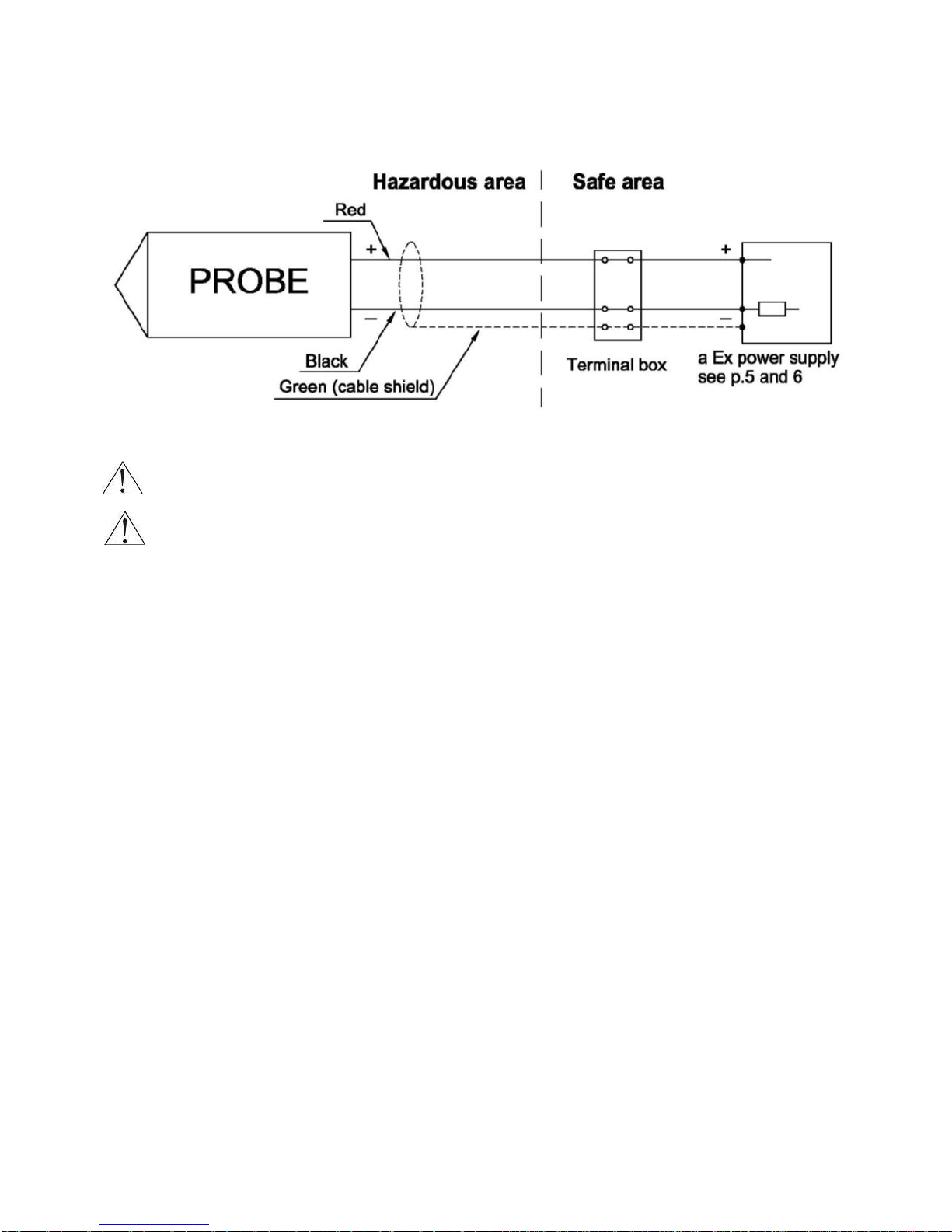
FIGURE 3A. CONNECTION OF SGE-25,SGE-16, SGE-25S AND SGE-25C IN A TWO-WIRE SYSTEM (4…20MA
OUTPUT SIGNAL)........................................................................................................................................ 19
FIGURE 4. SGE-25, SGE-16, SGE-25C PROBES IN LOW VOLTAGE VERSIONS –DIMENSIONS ............................ 20
FIGURE 4A. CONNECTION OF SGE-25, SGE-25S AND SGE-25C IN A THREE-WIRE SYSTEM (0…10V OUTPUT
SIGNAL) .................................................................................................................................................... 20
FIGURE 5. THE PROBE IN EX-VERSION WITH A CABLE WITH TEFLON SHIELD....................................................... 21

E3 2 DTR.SG...05(ENG)
I. APPENDIX Ex.03 (SGE–25.SMART, SGE–25S.SMART, SGE–25C.SMART)
SMART LEVEL PROBES
type: SGE–25.SMART, SGE–25S.SMART, SGE–25C.SMART
Ex VERSIONS
1. Introduction
1.1. This “Appendix Ex.03” applies only to smart level probes SGE–25.SMART, SGE–25S.SMART,
SGE–25C.SMART in Ex versions, marked on the rating plate as shown in 2.2 and denoted Ex in the
Product Certificate.
1.2. The appendix contains supplementary information relating to the Ex versions of the SGE–25.SMART,
SGE–25S.SMART, SGE–25C.SMART probes. During installation and use of Ex probes reference should
be made to DTR.SG...05(ENG) in conjunction with “Appendix Ex.03”.
2. Use of smart level probes in danger zones
2.1. The probes are produced in accordance with the requirements of the following standards:
EN 60079-0:2012+A11:2013, EN 50303:2000, EN 60079-11:2012.
2.2. The probes may operate in areas where there is a risk of explosion, in accordance with the rating of the
explosion protection design:
II 1G Ex ia IIC T4/T5/T6 Ga
II 1G Ex ia IIB T4/T5/T6 Ga (for probe with teflon-shielded cable)
I M1 Ex ia I Ma
KDB 11 ATEX 140X
3. Identifying marks
Probes in Ex version have a rating plate containing the information specified in paragraph 4 of
DTR.SG...05(ENG), and also at least the following:
- “CE”mark and number of notified unit: 1453 in the case of GIG KDB;
- “Ex” mark, designation of explosion protection design, certificate number;
- Values of parameters such as Ui, Ii, Ci;
- Year of manufacture;
- Inscription: "Version SA" - for probes with the protection against overvoltage (surge arrester).
4. User information
Together with the ordered probes, the user will receive:
a. Product Certificate;
b. Declaration of conformity;
c. Copy of certificate (on request);
d. User’s Manual named: DTR.SG...05(ENG) with Appendix Ex.03.
Items b), c), d) are available on www.aplisens.pl
5. Permitted input parameters of the smart level probes (based on data from
the KDB 11 ATEX 140X certificate and certification documentation)
Probes should be powered via the associated power supply and measurement devices provided with
the relevant intrinsic-safe certificates whose parameters of their outputs to the danger zone should not
exceed the permitted power supply parameters.
Probes in "Version SA" should be powered with the devices with galvanically isolated power supply.
- Permitted input parameters for power supply with a linear output characteristic: Ui=30V DC; Ii=0.1A
- Permitted input parameters for power supply with a rectangular output characteristic and trapezoidal
output characteristic: Ui = 24V DC; Ii = 0.1A.
1453

E3 3 DTR.SG...05(ENG)
Appendix Ex.03 (SGE–25.SMART, SGE–25S.SMART, SGE–25C.SMART)
Pi for all type of power supply; see table below.
Pi[W]
Ta[ºC]
Temperature class
0.75
50
T6
70
T5
80
T4, group I
1.2
40
T6
65
T5
80
T4, group I
Ta –ambient temperature (temperature of measuring medium).
Input inductance and capacity: Ci = 11nF*; Li = 0.611mH
*) One should take into account the capacity and inductance of the cable, which permanently connected cable
are: CK= 0.2nF/m and LK= 1µH/m.
Input capacitance CWand input inductance LWof the probes taking into account the parameters of the
permanently connected cable are accordingly:
CW= Ci + a·CK= 11nF + a·0.2nF/m; LW= Li + a·LK= 0,611mH + a ·1µH/m
a - length of the mounted permanently cable in meters.
5.1. Special conditions for safe use:
Version of device with surge arrester, marked on the plate "Version SA", does not meet the 500V rms
isolation test required by EN-60079-11. This must be taken into account when installing the
equipment (see p.5).
6. Supply examples
6.1. Power supply with a linear output characteristic may be e.g. a typical barrier with parameters:
Uo=28V; Io=0.093A; Rw=300Ω
Fig.1. Power supply from a source with linear output characteristic
6.2. Example of power supply from a source with trapezoidal output characteristic (see Fig.2).
Uo=24V; Io=0.05A
Fig. 2. Power supply from a source with trapezial output characteristic
If Uo < ½ UQthen UQ= , Rw = , Po =
For power supply with rectangular output characteristic:
Supplementary attentions: The supply of power from a source with a rectangular output characteristic means
that the voltage of the Ex power supply remains constant until current limitation activates.
The protection level of power supplies with a rectangular characteristic is normally “ib”.
The probe powered from such a supply is also an Ex device with protection level “ib”.
Example of practical provision of power supply with a rectangular characteristic:
use a stabilized power supply with Uo=24V with protection level „ib” and current limited to 25mA < Io < 30mA
6.3. The protection level
The probe is Ex device with protection level „ia” when the powered circuit have protection level „ia”.
The probe is Ex device with protection level „ib” when the powered circuit have protection level „ib”.
Probe
Example of practical provision of power supply
for case a) use the barrier with the parameters
given above.
Probe
UQ
Io
4Po
Io
Uo (UQ-Uo)
Rw
i

E3 4 DTR.SG...05(ENG)
Appendix Ex.03 (SGE–25.SMART, SGE–25S.SMART, SGE–25C.SMART)
Fig.3. SGE–25.SMART, SGE–25S.SMART, SGE–25C.SMART probes in Ex version –connection method
Devices in the measurement loop of the probe should be connected in accordance with
intrinsic safety and explosion protection standards.
It is not permitted to repair or otherwise interfere with the probe’s electrical circuits in any way.
Damage and possible repair may be assessed only by the manufacturer or another authorized
party.

E3 5 DTR.SG...05(ENG)
II. APPENDIX Ex.04 (SGE–25, SGE–25S, SGE–25C)
HYDROSTATIC LEVEL PROBES
type: SGE–25, SGE–25S, SGE–25C
Ex VERSIONS
1. Introduction
1.1. This “Appendix Ex.04” applies only to hydrostatic level probes SGE-25, SGE-25C and SGE-25S in Ex
versions, marked on the rating plate as shown in p.2.2 and denoted Ex in the Product Certificate.
1.2. The appendix contains supplementary information relating to the Ex versions of the SGE–25, SGE–25C,
SGE–25S probes. During installation and use of Ex probes reference should be made to
DTR.SG...05(ENG) in conjunction with “Appendix Ex.04”.
2. Use of hydrostatic level probes in danger zones
2.1. The probes SGE–25, SGE–25S, SGE–25C are produced in accordance with the requirements of
the following standards: EN 60079-0:2012+A11:2013, EN 60079-11:2012, EN 60079-26:2007,
EN 50303:2000.
2.2. The probes may operate in areas where there is a risk of explosion, in accordance with the rating of the
explosion protection design:
II 1G Ex ia IIC T4/T5/T6 Ga
II 1G Ex ia IIB T4/T5/T6 Ga (for probe with teflon-shielded cable)
I M1 Ex ia I Ma
KDB 09 ATEX 007X
3. Identifying marks
The above mentioned probes in Ex version must have a rating plate containing the information specified in
paragraph 4 of DTR. SG...05(ENG), and also at least the following:
- “CE”mark and number of notified unit: 1453 in the case of GIG KDB;
- “Ex” mark, designation of explosion protection design, certificate number;
- Values of parameters such as Ui, Ii, Ci;
- Year of manufacture;
- Inscription: "Version SA" - for probes with the protection against overvoltage (surge arrester).
4. User information
Together with the probes ordered, the user will receive: User’s Manual numbered DTR.SG...05(ENG) with
Appendix Ex.04, and also the Product Certificate.
5. Permitted input parameters of the SGE–25, SGE–25S, SGE–25C probes
(based on data from the KDB 09 ATEX 007X certificates and certification
documentation)
Probes should be powered via the associated power supply and measurement devices provided with
the relevant intrinsic-safe certificates whose parameters of their outputs to the danger zone should not
exceed the permitted power supply parameters specified in points 5a and 5b.
Probes in "Version SA" should be powered with the devices with galvanically isolated power supply.
Minimum supply voltage for probe is 9 V DC.
The probe is an intrinsically safe (Ex) device with protection level „ia” when the powered circuit have
protection level „ia”.
a) Permitted input parameters for power supply with a linear output characteristic
Ui = 28V DC; Ii = 0.1A
b) Permitted input parameters for power supply with a rectangular output characteristic and trapezoidal
output characteristic
Ui = 28V DC; Ii = 0.08A
Input inductance and capacity: Ci = 25nF; Li = 0.4mH
*) It should take into account the capacitance and inductance of the cable, which for permanently connected
cable are: Ck= 0.2nF/m and Lk=1µH/m.
Input capacitance Cw and input inductance Lw taking into account the parameters of the permanently attached
cable: Cw = Ci + a ·Ck = 11nF + a ·0.2nF/m; Lw= Li + a ·Lk = 1000µH + a ·1µH/m
a - length of the permanently mounted cable in meters.
1453

E3 6 DTR.SG...05(ENG)
Appendix Ex.04 (SGE–25, SGE–25S, SGE–25C)
Pi for all type of power supply; see table Z1.
Table Z1
Pi [W]
Ta [ºC]
Temperature class
0.7
50
T6
80
T5, T4, group I
1.2
40
T6
75
T5
80
T4, group I
Ta –ambient temperature (temperature of measuring medium).
6. Supply examples
6.1. Power supply with a linear characteristic may be e.g. a typical barrier with parameters:
Uo=28V Io=0.093A Rw=300
Fig.1. Power supply from a source with linear output characteristic
6.2. Example of power supply from a source with trapezoidal output characteristic (see Fig.2).
Uo=24V; Io=0.05A
Fig. 2. Power supply from a source with trapezoidal output characteristic
If Uo < ½ UQthen UQ= , Rw = , Po =
For power supply with rectangular output characteristic:
The supply of power from a source with a rectangular output characteristic means that the voltage of the Ex
power supply remains constant until current limitation activates.
The protection level of power supplies with a rectangular characteristic is normally “ib”. The probe powered
from such a supply is also an Ex device with protection level “ib”.
Example of practical provision of power supply with a rectangular characteristic:
–use a stabilized power supply with o Uo=24V with protection level „ib” and current limited to Io=50mA.
Example of practical provision of power supply: use
the barrier with the parameters given above.
probe
UQ
Io
4Po
Io
Uo(UQ-Uo)
Rw
probe

E3 7 DTR.SG...05(ENG)
Appendix Ex.04 (SGE–25, SGE–25S, SGE–25C)
6.3. Protection level
The probe is Ex device with protection level „ia” when the powered circuit have protection level „ia”.
The probe is Ex device with protection level „ib” when the powered circuit have protection level „ib”.
Fig.3. SGE–25, SGE–25S, SGE–25C probes in Ex version –connection method
Devices in the measurement loop of the probe should be connected in accordance with
intrinsic safety and explosion protection standards.
It is not permitted to repair or otherwise interfere with the probe’s electrical circuits in any way.
Damage and possible repair may be assessed only by the manufacturer or another authorized
party.
Special conditions for safe use:
Probes with surge arrester, marked on the rating plate version “SA”, does not meet the
500V rms isolation test required by EN 60079-11. This must be taken into consideration during
the installation of probe (see p.5).

E3 8 DTR.SG...05(ENG)
1. INTRODUCTION
1.1. This manual is intended for users of SGE-25.SMART, SGE-25S.SMART, SGE-25C.SMART,
SGE-25S.SMART/TITAN, SGE-25, SGE-25S, SGE-25C and SGE-16 hydrostatic level probes containing the
data and guidelines necessary to understand the functioning of the probes and how to operate them.
It includes essential recommendations concerning installation and use, as well as emergency procedures.
1.2. The SGE-25, SGE-25S, SGE-25C and SGE-25SMART, SGE-25S.SMART, SGE-25C.SMART are
also made in Ex version.
Additional data on the probes in Ex version is contained in the appendix designated
“DTR.SG...05(ENG). Appendix.Ex.04” or “DTR.SG...05(ENG). Appendix.Ex.03”.
During installation and use of the probes in Ex version, reference should be made to
DTR.SG...05(ENG) in conjunction with Appendix Ex.
1.3. The level probes: SGE-25, SGE-25S, SGE-25C, SGE-25SMART, SGE-25S.SMART and
SGE-25C.SMART in realization for sea uses are complied with Det Norske Veritas (DNV) Rules for
Classification of Ships, High Speed & Light Craft and Det Norske Veritas' Offshore Standards. Certificate
No. A-13386 for application in following Location Classes: Temperature C, Humidity: B, Vibrations: B,
EMC: B, Enclosure: D(see Standard for Certification No 2.4).
2. USER MATERIALS
The level probes are delivered in single and/or multiple packs.
Together with the probe are delivered:
a. Product certificate, which is also as the warranty card;
b. Declaration of conformity (on request);
c. Copy of ATEX certificate (on request);
d. User’s Manual numbered „DTR.SG...05(ENG)”.
Items b), c), d) are available at:www.aplisens.pl
3. APPLICATIONS OF PROBES
The SGE-25.SMART, SGE-25S.SMART, SGE-25C.SMART, SGE-25S.SMART/TITAN, SGE-25, SGE-25S,
SGE-25 and SGE-16 probes are designed to measure the depth of liquid in wells, tanks, watercourses,
boreholes etc.
The SGE-25S.SMART and SGE-25S probes are particularly designed for the measurement of levels of liquid
waste and of dense or viscous.
The SGE-16 probes, due to their small diameter, are designed for the measurement of water levels in wells and
boreholes, wherever it is necessary to insert probes into pipes of small diameter.
Probes fitted with cables with anadditional Teflonshieldmay be used with food productsand with reactive substances.
The SGE-25, SGE-16, SGE-25C, SGE-25S probes convert an input pressure (being a measure of the level of the
medium) into a standard 4÷20 mA signal transmitted in a two-wire system, or in special versions into a 0÷10V
signal transmitted in a three-wire system.
The SGE-25.SMART, SGE-25S.SMART, SGE-25C.SMART, SGE-25S.SMART/TITAN probes generate
a 4÷20mA output signal and a digital HART signal in a two-wire system (current loop).
4. IDENTIFYING MARKS. ORDERING PROCEDURE
4.1. Identifying marks on a rating plate
Every probe carries a rating plate containing at least the following information: CE mark, numbers of notified
institutions and designations of certificates obtained, name or logo of manufacturer, type, factory number,
basic range, output signal, power supply voltage.
Probes for marine uses are equipped in additional rating plates with the DNV certificate number, and signs of
environmental classes.
4.2. Ordering procedure
See the catalogue cards.
i

E3 9 DTR.SG...05(ENG)
5. TECHNICAL DATA
5.1. Technical data. SGE-25.SMART, SGE-25S.SMART, SGE-25C.SMART,
SGE-25S.SMART/TITAN probes
5.1.1. SGE-25.SMART, SGE-25S.SMART, SGE-25C.SMART and SGE-
25S.SMART/TITAN. Measurement Ranges
Type of probe
Basic range
(FSO)
Minimum set range
Overpressure limit
(without hysteresis)
SGE-25.SMART
SGE-25S.SMART
0 ÷1,5 mH2O
0,15 mH20
15 mH20
0 ÷ 10 mH20
0,8 mH20
100 mH20
SGE-25.SMART
0÷100 mH20
8 mH20
700 mH20
SGE-25C.SMART
0 ÷ 10 mH20
0.8 mH20
100 mH20
SGE-25S.SMART/TITAN Measurement ranges:
Basic range 0 ÷10 mH2O
Minimum set range 0,8 mH2O
5.1.2. SGE-25.SMART, SGE-25C.SMART. Metrological parameters
Accuracy ≤ ± 0.1 % for the basic range
≤ ± 0.3 % for range 0…10% FSO
Long term stability ≤ 0.1 % (FSO) for 2 years
Thermal error < ± 0.08 % (FSO) / 10ºC
< ± 0.2 % for the whole thermal compensation range
Thermal compensation range -25 ÷ 80ºC
Error due to supply voltage changes 0.002% (FSO) / 1V
5.1.3. SGE-25S.SMART, SGE-25S.SMART/TITAN Metrological parameters
Accuracy ≤ ± 0.16 % for the basic range
≤ ± 0.4 % for range 0…10% FSO
Thermal error < ± 0.08 % (FSO) / 10ºC
< ± 0.2 % for the whole thermal compensation range
Additional absolute zero error related
to changes in the medium temperature up to 80 Pa/10ºC
Thermal compensation range -25 ÷ 80ºC
Error due to supply voltage changes 0.002% (FSO) / 1V

E3 10 DTR.SG...05(ENG)
5.1.4. SGE-25.SMART, SGE-25S.SMART, SGE-25C.SMART and
SGE-25S.SMART/TITAN. Electrical parameters
Type of probe
Power supply
SGE-25.SMART
SGE-25S.SMART
SGE-25C.SMART
SGE-25S.SMART/TITAN
7.5 ÷55V DC
SGE-25.SMART / Ex
SGE-25S.SMART / Ex
SGE-25C.SMART / Ex
7.5 ÷30V DC
More information for Ex-version see “Appendix Ex.03”.
Output signal 4...20 mA + HART
or inverse 20...4 mA two wire transmission
Load resistance R[Ω] ≤
Communication is carried out via HART transmission protocol and signal of 4÷20mA. For this purpose:
KAP-03, KAP-03Ex communicator, HART/RS232 converter or HART/USB Converter (APLISENS) or another
converter, PC computer and Raport 2 programme can be used (see p. 9).
Resistance required for communication 240...1100 Ω,
Minimum supply voltage for Umin.[V] = RL[Ω] x 0.0225 A + 7.5 V
specified load resistance RL[]
Additional electronic damping 0...30 s
Voltage for insulation testing 500 V AC or 750 V DC
–versions “normal” and “SA” 100 V DC
Excess voltage protection see p. 10.2.2
5.1.5. SGE-25.SMART,SGE-25C.SMART, SGE-25S.SMART AND
SGE-25S.SMART/TITAN. Permitted Environmental Conditions
Process temperature limit -30...40ºC - standard
0...80ºC - for special versions
Maximum process temperatures for Ex version see “Appendix Ex.03” for SGE-25.SMART,
SGE-25S.SMART and SGE-25C.SMART.
The medium must not be allowed to freeze in the immediate vicinity of the probe.
5.2. Technical Parameters of the SGE-25
Any measurement range 1...500 m H2O for normal version
1...100 m H2O for Ex version
Recommended standard ranges 4, 10, 20, 50, 100 m H2O
Measurement Range
1 mH2O
4 mH2O
10 mH2O ÷ 500 mH2O
Overpressure Limit
(repeatable–without hysteresis)
40 x range
25 x range
10 x range (max. 700 mH2O)
Accuracy % FSO acc. to IEC 60770
0.6 %
0.3 %
0.2 %
Accuracy % FSO acc. to BFSL
0.3 %
0.15 %
0.1 %
Thermal error
typical 0.3% / 10ºC
max 0.4% / 10ºC
typical 0.2% / 10ºC
max 0.3% / 10ºC
Usup [V] –7.5 V
0,0225 A

E3 11 DTR.SG...05(ENG)
Hysteresis, repeatability 0.05%
Long term stability 0.1% or 1 cm H2O for 1 year
Thermal compensation range 0 ÷ 40ºC – standard
-10 ÷ 70ºC – for special version
Medium temperature range -25 ÷ 40ºC – standard
0 ÷ 75ºC – for special version
Maximum process temperatures for Ex version see “Appendix Ex.04” for SGE–25, SGE–25S,
SGE-25C.
The medium must not be allowed to freeze in the immediate vicinity of the probe.
5.3. Technical Parameters of the SGE-25S, SGE-25C
Any measurement range 2...20 mH2O for normal and Ex-version
Recommended standard ranges 2, 5, 4, 10 mH2O
Measurement Range
2,5 mH2O
4 mH2O
10 mH2O ÷ 20 mH2O
Overpressure Limit
(repeatable–without hysteresis)
20 x range
20 x range
10 x range
Accuracy % FSO acc. to IEC 60770
1,5%
1%
0.5%
Accuracy % FSO acc. to BFSL
0,75%
0,5%
0.25%
Thermal error of zero
typical 0.4% / 10ºC
max 0.6% / 10ºC
typical 0.2% / 10ºC
max 0.3% / 10ºC
Thermal error of span
typical 0.3% / 10ºC
max 0.4% / 10ºC
typical 0.2% / 10ºC
max 0.3% / 10ºC
Hysteresis, repeatability 0.05%
Thermal compensation range 0 ÷ 40ºC – standard
-10 ÷ 70ºC – for special version
Medium temperature range -25 ÷ 40ºC – standard
0 ÷ 75ºC – for version with ETFE and PTFE cable
Maximum process temperatures for Ex version see “Appendix Ex.04” for SGE–25, SGE–25S,
SGE-25C.
The medium must not be allowed to freeze in the immediate vicinity of the probe.
5.4. Technical Parameters of the SGE-16
Measurement ranges 10; 20; 50; 100 mH2O
Accuracy 0.3%
Hysteresis, repeatability 0.05%
Overpressure limit (repeatable –without hysteresis) 10 x range
Thermal compensation range 0 ÷ 40ºC
Process temperature limit 0 ÷ 40ºC
0 ÷ 75ºC – for version with ETFE and PTFE cable

E3 12 DTR.SG...05(ENG)
5.5. SGE-25, SGE-16, SGE-25S, SGE-25C. Electrical parameters
Type of probe
Signal type
Power supply
SGE-25
SGE-25S
SGE-25C
4 ÷20 mA
8 ÷36V DC
10.5 ÷36V DC
for TR version
SGE-25/Ex
SGE-25S/Ex
SGE-25C/Ex
4 ÷20 mA
9 ÷28V DC
12 ÷28V DC
for TR version
SGE-25
SGE-25S
SGE-25C
0 ÷10 V
13 ÷30V DC
SGE-25
0 ÷3.3 V
4.1 ÷14.1V DC
SGE-25
0 ÷5 V
0.5 ÷4.5 V
8 ÷14.1V DC
SGE-16
4 ÷20 mA
10.5 ÷36V DC
SGE-16
0 ÷3.3 V
3.6 ÷4.5 V DC
Output signal 4 ÷ 20mA, two wire transmission
Load resistance R[Ω]≤
(for current output)
More information for Ex-version see “Appendix Ex.04” for SGE–25, SGE–25S, SGE-25C.
*) Insert the minimum supply voltage according to the table above.
5.6. Construction Materials: (for whole probes)
Diaphragm Stainless steel 1.4404/1.4435 (316L)-for SGE-16, SGE-25S, SGE-25S.SMART
Hastelloy C276 –for SGE-25, SGE-25.SMART, SGE-25C
Sensing module Stainless steel 1.4404 (316L)
Casing for electronic parts Steel pipe 1.4404 (316L)
Liquid filing the interior of the sensing module Silicone oil
Cable shield polyurethane
Additional cable shield Teflon (fitted by arrangement)
5.7. Ingress protection rating
SGE-25.SMART, SGE-25S.SMART, SGE-25, SGE-25S,
SGE-25C and SGE-16 IP68
Usup [V] –8* V
0,02 A

E3 13 DTR.SG...05(ENG)
6. TECHNICAL DESCRIPTION
6.1. Principles of Operation
The hydrostatic level probes work by converting changes in the resistance of a piezoresistive bridge, which
are proportional to the pressure (of a hydrostatic column of liquid), into a standard current output signal.
The active sensing device is a silicon diaphragm with in-diffused piezoresistors.
6.2. Construction
6.2.1. The probe is composed of the active sensing device with silicon and sealing diaphragm, and plate with
the electronic components.
The SGE-25S.SMART and SGE-25S probes are additionally fitted with a diaphragm seal enabling measuring
the depth of dense media and media with suspended matter and impurities, such as liquid waste (fig. 1, 3).
The output signal is passed through a special cable with a capillary used to connect the negative side of
the measuring diaphragm to the atmosphere.
6.2.2. Special versions of the probes can be produced with cables shielded by an additional teflon layer.
The shield covers the parts of the cable while is immersed in the medium being measured, as well as
a necessary additional segment.
The Teflon shield (in Ex version) is additional equipped in stainless steel cord escorted electrostatic charges
(see fig. 5).
6.2.3. The probes are fitted with elements ensuring excess voltage protection: „transil” diodes between the
wires, and plasma surge arresters between the wires and the casing.
The plasma surge arresters are assembled in normal and "Version SA" only.
6.3. Electronic circuit of the probes
Electronic circuit can be produced in two versions:
6.3.1. The digital version (SGE-25.SMART and SGE-25S.SMART probes).
The electronic circuit changes the signal from the sensing module into digital signal and input to
a microprocessor, which controls the probe’s operation. Using data input during the production process,
the processor processes the conversion curve, adjusts for thermal errors and carries out linearization.
After processing, the digital signal is again converted into an analogue 4÷20mA current signal, with
a superimposed digital communication HART signal.
6.3.2. The analog version (SGE-25, SGE-25S, SGE-25C and SGE-16 probes).
The electronic circuit changes the signal from the sensing module into an output signal 4...20 mA.
The electronic circuit is equipped in filter elements assured resistance on conducted and radiated disturbances
and electric impulse.
7. PLACE OF INSTALLATION
7.1. The level probes installed in places where liquid levels are measured in wells, tanks, boreholes etc. The
probe is immersed in the medium being measured. A special cable extends above the level of the medium;
this can be connected directly to another device or to a terminal box.
7.2. High and Low Ambient Temperatures and Medium Temperatures
When measuring liquids whose solidification point is above the ambient temperature, the medium should not
be allowed to freeze around the probe, this applies in particular to water in the case of open-air installations.
For maximum medium temperatures see sect. 5.
Data for versions Ex in accordance with Appendix Ex.03, Appendix Ex.04.

E3 14 DTR.SG...05(ENG)
8. INSTALLATION AND CONNECTION
8.1. Mechanical Installation
The probe can be suspended from the power supply cable e.g. using the handle SG prod. Aplisens.
If the probe will often be removed or, when during the pull, there is the possibility of hitching protruding
elements it is recommended to suspend the probe on a steel cable using the supporting handle (not applicable
to SGE-16). If the cable is to be exposed to current or turbulence, it should be installed in a protective tube,
e.g. one made from PCV.
Directly before location the probe in measured medium to take off from diaphragm seals
SGE-25S, SGE-25S.SMART, SGE-25C the securing covers.
Protect the level probe from impacts during installation.
The probe with an additional Teflon shield suspends on a steel cable or on an internal cable (do not
catch for teflon).
The probe in Ex-version with a cord for earthing suspend on a steel cable using the lifting handle.
8.2. Electrical Connection
The method ofmaking electrical connections is shown in figure 2, 3A, 4A (forEx version in figure 3 „Appendix Ex”).
If the transmission line leads to remote premises via the open air, it is recommended that a terminal box
be fitted, e.g. the Aplisens type PP, in order to connect the probe’s cable to the remaining section of the
transmission line. The box should have an IP65 ingress protection rating, and but should not be so airtight as
to prevent the probe’s active sensing device from “breathing” via a capillary embedded in the cable.
The opening of the capillary should not be allowed to become dirty, and water should not be allowed to enter
the capillary.
Where the transmission line is very long, it is recommended that the section leading from the end of the probe
cable be made from twisted pair cable, and it is desirable that entry points to other devices be fitted with
excess voltage protection, e. g. the Aplisens UZ-2 system.
The cable of the probe and the remaining section of the transmission line should be protected from
mechanical damage.
From the probe power supply is led cable screen (green wire). The manufacturer recommends connecting the
probe cable shield to the ground point measuring system; grounding of the cable shield is particularly
appropriate in an environment of large EMC; e.g. the pumping station when the cable passes the test probes
power cable supply pump. Cable shield in work station with battery may, but need not be grounded.
9. SETTINGS AND REGULATION
9.1. Settings of SGE-25, SGE-16, SG-25C, SGE-25S probes
The SGE-25, SGE-16, SGE-25C, SGE-25S are factory set to the range stated in the order. The user does not
have access to the “zero” and “range” potentiometers. Setting may be adjusted by the manufacturer only.
9.2. Settings of SGE-25.SMART, SGE-25S.SMART, SGE-25S.SMART/TITAN
probes
The SGE-25.SMART and SGE-25S.SMART probes are equipped with a smart electronic and HART
communication system, thought which the user can make e.g. set „zero” and measurement ranges.
9.3. SGE-25.SMART, SGE-25S.SMART, SGE-25S.SMART/TITAN.
Measurement ranges. Definitions
9.3.1. The maximum range of level, while the probe can measure is called „basic range” (for specifications
of “basic range” see 5.1.1).
The width of the basic range is the difference between the upper and lower limits of the basic range.
The internal characteristic conversion curve for the basic range is coded in the probe’s memory.
This is the reference curve used when making any adjustments which affect the probe’s output signal.
9.3.2. When the probe is in use the term “set range“ is used.
The set range is the range whose lower end-point corresponds to an output current of 4mA and whose upper
end-point corresponds to a current of 20mA (or 20mA and 4mA respectively when the conversion curve
inverted). The set range may cover the whole of the basic range or only a part of it. The width of the set range
is the difference between the upper and lower limits of the set range. The probe may be set to any range
within the basic range of level values, subject the restrictions set out in the table in 5.1.1.
i

E3 15 DTR.SG...05(ENG)
9.4. Configuration and Calibration
9.4.1. The SGE-25.SMART, SGE-25S.SMART, SGE-25C.SMART, SGE-25S.SMART/TITAN probes have
features which enable metrological and identification parameters to be set and altered. The configurable
metrological parameters affecting the probe’s output signal include the following:
a) Unit in which the measured level is expressed on the display;
b) Upper end-point of the set range;
c) Lower end-point of the set range;
d) Time instant;
e) Type of characteristic curve: linear or radical.
Parameters of an informational nature which cannot be altered include the following:
a) Upper limit of the basic range;
b) Lower limit of the basic range;
c) Minimum set range.
9.4.2. Other identification parameters, not effecting the output signal, include: device address, device code,
factory identification code, factory device code, number of preambles (3÷20), UCS, TSD, program version,
electronics version, flags, factory number, label tag, description tag, date tag, message, record number,
sensing module number.
The process of setting the parameters listed in 9.4.1 and 9.4.2 is called “Configuration”.
9.4.3. It is possible to adjust the probe’s zero point, for example to compensate for deviation resulting from
a change in position of installation.
The probes may also be calibrated, by taking readings with the input pressure controlled using a standard
device. These process and zero-point adjustments are called “Calibration”.
9.4.4. Configuration and Calibration of the probe are carried out using an Aplisens KAP-03 or KAP-03Ex
communicator, certain HART communicators or a PC with HART/RS232 converter and Aplisens “Raport2”
software.
Catalogue cards and user manuals for Aplisens communication tools (KAP communicator, HART/RS232
converter and “Raport 2” programme) can be found on the manufacturer website www.aplisens.pl.
After configuration it is important to protect the transducers using command HART [247].
During work probe should be safe prior to entries. This prevents accidental or intentional
changes configurational data. The protection function is accessible in KAP-03 communicator,
“Raport2” software, as well as, in applying DD or DMT programs libraries.
10. INSPECTIONS, REPAIRS AND SPARE PARTS
10.1. Regular inspections
10.1.1. Regular inspections should be carried out in accordance with the regulations to which the user subject
An inspection should be made of the external condition of the probe, during which:
a) Check that there are no signs of mechanical damage in the form of impact marks or dents;
b) Check the condition of the cable, which should not show signs of wearing, bending or fraying of the
external coating; check the condition of the packing gland.
Every two years or in accordance with regulations applicable to the user, check the zero point (4mA).
10.1.2. Check the „zero point” (SGE-25, SGE-25S and SGE-25C) bring the probe up above the surface of
the liquid and read the output current. In case of excessive deviation of the zero reading, return the probe to
the manufacturer for adjustment of the conversion curve or adjust the zero point of a device used
in conjunction with the probe (e.g. monitor, regulator, and controller).
10.1.3. Check the „zero point” SGE-25.SMART, SGE-25S.SMART, SGE-25S.SMART/TITAN see 10.1.2.
10.2. Additional Inspections
If the probe is installed in a place where it might have been subject to mechanical damage, wearing cable
covering, excess pressure, hydraulic impulses, sedimentation, crystallization or erosion of the diaphragm,
or excess electrical voltage, inspections should be made as necessary.
Check the state of the diaphragm and cable, clean the diaphragm, and check the zero point.

E3 16 DTR.SG...05(ENG)
10.2.1. Faults in the Transmission Line
If there is no current in the line or the value of the current is random, check the transmission line,
the connections with the terminal adapters, connectors etc.
If the transmission line is in good order, check whether the probe is functioning correctly.
10.2.2. Protection from Excess Voltage
The probe may be in danger from excess voltage caused by connection faults or atmospheric electrical
discharge.
Protection from excess voltage between the wires of the transmission line is provided by TVS diodes installed
in all types of probe (see the table, column 2).
In order to protect against excess voltage between the transmission line and the casing or earth
(not prevented by the diodes connected between the transmission wires), additional protection is provided in
the form of plasma surge arresters (see the table, column 3).
Also external protective devices may be used, e.g. the UZ-2 Aplisens system, or others.
Internal protection of probes:
1
2
3
Type of probe
Protection between wires (TVS
diodes) –permitted voltage
Protection between wires and earth and/or casing –
type of protection, permitted voltage
SGE-25.SMART,
SGE-25
series
68V DC
Plasma surge arresters - 230V DC
(only in normal and “SA”versions)
The voltage in the protective elements must not exceed the maximum permitted values given in columns 2 and
3 of the table.
The insulation test voltages 500V AC or 750V DC refer to transmitters with plasma surge arresters.
In case of a large surge of excess voltage between the wires of the line, thesafety diode may sustain damage due
to a low-resistance short circuit (a diode damaged in this way still provides protection to the probe’s circuits).
Symptoms of damage:
- When the probe is connected to the power supply, the value of the current exceeds 20 mA, and the
voltage on the probe is of an order of several hundred mV (in extreme cases a particularly strong
surge may cause circuits or wires inside the probe to burn out; the current is then 0 mA and there is
full voltage in the output circuit);
- When the probe is not connected to a power supply, the resistance of the probe should be measured;
this is approximately 10and is equal to the value of the limiting resistors + resistance of the
damaged diode.
Damage to the gas-filled spark gap (Plasma surge arresters) is much less likely than damage to the diode, and
may lead to a short circuit or a lowering of the resistance of the spark gap.
10.2.3. Damage Caused by Overpressure
Another possible reason for malfunctioning of the probe is damage caused by overpressure, which may result
from such factors as
a) Freezing of the medium;
b) Dynamic effects of a strong current of liquid on the diaphragm seal while the probe is being washed
(applies mainly to the SGE-25S, SGE-25S.SMART model);
c) Striking or scraping of the diaphragm with a hard object, such as a screwdriver.
If excess pressure on the probe has caused damage to the silicon or sealing diaphragm, the probe can
no longer be used. Symptoms of such damage are generally such that the output current falls below 4 mA or
rises above 20 mA, and the probe fails to react to input pressure.
10.2.4. Cleaning the Diaphragm Seal
Impurities which have accumulated on the diaphragm during operation should not be removed by mechanical
means such as scraping, scrubbing etc., as this may cause damage. The only permitted method is to dissolve
the impurities, possibly aiding their removal with a light brush.
Sedimentation on the diaphragm may affect the conversion curve.
After removing sedimentation, parts which have come into contact with the solvent substance
should be thoroughly rinsed, and the health and safety regulations relating to the chemical
in question should be adhered to.
Do not use substances which might cause corrosion of the diaphragm seal.
i
i

E3 17 DTR.SG...05(ENG)
10.3. Spare Parts
The following parts of the probe can be replaced when worn or damaged: cable, seals on the packing gland.
The cable may be replaced by the manufacturer only.
11. PACKING, STORAGE AND TRANSPORT
11.1. Packing, Transport
The probes should be packed in such a way as to protect them from damage during transportation, in single or
multiple packs. The cable should be rolled into a loop 300 mm in diameter, secured so as to prevent the coils
from moving relative to each other and the whole from moving within the package. Avoid breakage to the
cable at the point where it enters the packing gland. Land, sea or air transport may be used, provided that
direct action of atmospheric effects is prevented.
11.2. Storage
The probes should be stored in multiple packs under cover, in a place free of vapours and reactive
substances, with temperature and humidity not exceed the limits for specific probes.
12. GUARANTEE
Manufacturer warrants under the conditions specified in the Product Certificate which is also a guarantee card.
13. SCRAPPING, DISPOSAL
Waste or damaged probes should be dismantled and disposed of in accordance with Directive (2012/19/UE)
on waste electrical and electronic equipment (WEEE) or returned to the manufacturer.
14. ADDITIONAL INFORMATION
Related standards:
EN 60529:1991/A2:2013 Ingress protection rating of casing. (IP code)
EN 61010-1:2010 Safety requirements for automated electrical measuring devices and
laboratory devices. General requirements.
15. LEVEL PROBE WITH INTERNAL TEMPERATURE SENSOR PT100
Electrical connections and wire colours in the probe power supply cable in the output signal 4 ... 20mA with
resistive temperature sensors.
Level probe
red: “+”probe power supply
black: “–“ probe power supply
green: cable shield (if it is led out)
Resistance sensor
white
white
sensor in the four-wire connection
brown
brown
white
sensor in the three-wire connection
brown
brown

E3 18 DTR.SG...05(ENG)
16. FIGURES
Zero
SGE-25S.SMART probe
level
60 ( 55)
25
130
25
147 (180)
shield
teflon covering
Cable with additional
Special version of probe.
Teflon tube
-
+
Green wire (shield)
Capillary 2x0,5
-
+
Black wire
Red wire
-
+
(shield)
Black wire
remove directly before assembling
SGE-25S.SMART/Tytan probe
(dimensions in brackets for
teflon covering)
SGE-25C.SMART
SGE-25.SMART
Supporting handle
Green wire
probe
157(SGE-25S.SMART)
140(SGE-25C.SMART)
166(SGE-25.SMART)
directly before location the probe
156(SGE-25.SMART)
To take off the securing cover
probe
Zero
level
25
level
Zero
14.5
Figure 1. SGE-25.SMART and SGE-25S.SMART probes –dimensions
Figure 2. SGE-25.SMART and SGE-25S.SMART probes –connection method
Other manuals for SGE-25.SMART
2
This manual suits for next models
7
Table of contents
Other Aplisens Measuring Instrument manuals

Aplisens
Aplisens PEM-1000 User manual

Aplisens
Aplisens WW-30Pt User manual

Aplisens
Aplisens SGE-25 User manual

Aplisens
Aplisens CS-27/W User manual

Aplisens
Aplisens WW-30 User manual

Aplisens
Aplisens PMS-970 User manual

Aplisens
Aplisens SGE-25.SMART User manual

Aplisens
Aplisens SGE-25.Modbus User manual

Aplisens
Aplisens SGE-25.Modbus User manual

Aplisens
Aplisens MS-100K User manual