Aplisens PEM-1000 User manual

IO.PEM-1000(ENG)
MARCH 2018
APLISENS S.A., 03-192 Warszawa, ul. Morelowa 7
tel. +48 22 814 07 77; fax +48 22 814 07 78
www.aplisens.pl, e-mail: [email protected]
USER’S MANUAL
ELECTROMAGNETIC FLOWMETER
PEM-1000
02.A.003

Used markings
Symbol
Description
Warning signifying that it is necessary to follow the information in
the documentation precisely in order to ensure device safety and complete
functionality.
Information particularly useful during device installation and operation.
Information concerning dealing with used equipment.
BASIC REQUIREMENTS AND SAFETY OF OPERATION
The manufacturer is not responsible for damage caused by improper
installation of the device, not maintaining the device in good technical
condition and operating the device contrary to its intended use.
Installation should be carried out by qualified personnel authorized to
install electrical devices and control and measuring equipment.
The installer is responsible for carrying out the installation in
accordance with this manual as well as safety and electromagnetic
compatibility standards and regulations applicable to a given type of
installation.
In case of an installation with control and measuring equipment, in
the event of a leak, medium under pressure causes a risk to
the personnel. During device installation, operation and inspection all
safety and precautionary requirements must be taken into account.
If the device malfunctions, it should be disconnected and handed over
to the manufacturer or to a body authorized by the manufacturer for
repairs.
In order to minimize probability of failure and resultant danger to personnel,
avoid installing the device under particularly unfavourable conditions when
the following dangers are present:
Danger of mechanical impacts, excessive shocks and vibrations.
Excessive temperature variations.
Vapour condensation, dust, icing.
Changes in product manufacture may precede an update to the user's paper documentation.
Up-to-date operating manuals can be found on manufacturer's website at www.aplisens.com
i

IO.PEM-1000(ENG)
02.A.003 3
TABLE OF CONTENTS
1. INTRODUCTION..........................................................................................6
2. SAFETY.......................................................................................................6
3. COMPLETENESS LIST...............................................................................6
4. TRANSPORT AND STORAGE....................................................................7
4.1. Transport.....................................................................................................................7
4.2. Storage .......................................................................................................................7
5. WARRANTY ................................................................................................7
6. DESIGN .......................................................................................................7
6.1. Intended use and properties .......................................................................................7
6.2. The operating principle................................................................................................8
6.3. Design and dimensions...............................................................................................9
6.3.1. The sensor design..............................................................................................10
6.3.2. Electrodes..........................................................................................................13
6.3.3. The converter design .........................................................................................14
6.4. Identification markings ..............................................................................................15
7. ASSEMBLY...............................................................................................16
7.1. General recommendations........................................................................................16
7.2. Recommended assembly method for the sensor......................................................17
7.3. Assembly of the compact version of the converter....................................................18
7.4. Assembly of the remote version of the flow meter.....................................................19
8. CONNECTION...........................................................................................20
8.1. Electrical connection of the flow meter......................................................................21
8.1.1. Power cable .......................................................................................................22
8.3. Earthing.....................................................................................................................25
8.3.1. Protective earth..................................................................................................25
8.3.2. Functional earthing.............................................................................................26
9. START-UP.................................................................................................28
10.TECHNICAL PARAMETERS.....................................................................28
10.1. Electrical connections ...............................................................................................28
10.1.1. Output signals....................................................................................................28
10.1.2. Power supply......................................................................................................28
10.2. Protection class.........................................................................................................28
10.3. Technical parameters................................................................................................29
10.3.1. Technical specification of the sensor .................................................................29
10.3.2. Technical specifications of the converter ...........................................................30
10.4. Reference conditions ................................................................................................31
10.5. Metrological parameters............................................................................................31
10.5.1. Standard measuring ranges...............................................................................31
10.5.2. Table of volumetric flows calculated for the characteristic flow velocities of the
medium for the versions with flanges according to DIN..................................................33
10.5.3. Available pressure ranges acc. to DIN, ANSI for operation of the flowmeters for
the individual versions for DN flanged connections........................................................35
IO.PEM-1000(ENG)
4 02.A.003
10.5.4. Basic principles for selection of the DN size (acc. to DIN) of the flowmeter for the
nominal flow Qn..............................................................................................................35
10.6. Allowable ambient and operation parameters ...........................................................36
10.6.1. Electromagnetic compatibility, immunity.............................................................37
10.6.2. Electromagnetic compatibility, emissions...........................................................37
10.6.3. Mechanical resistance........................................................................................37
10.6.4. Insulation resistance...........................................................................................37
10.6.5. Insulation resistance...........................................................................................37
10.6.6. Ingress protection of the enclosure ....................................................................37
11.INSPECTIONS. CLEANING. SPARE PARTS........................................... 38
11.1. Periodic inspections ..................................................................................................38
11.2. Non-periodic inspections...........................................................................................38
11.3. Cleaning/washing......................................................................................................38
12.SCRAPPING, DISPOSAL ......................................................................... 38
13.ADDITIONAL INFORMATION................................................................... 38
13.1. Additional information................................................................................................38
14.REVISION LOG......................................................................................... 38
LIST OF FIGURES
Figure 1. The flow meter PEM-1000ALW. The compact version.............................................9
Figure 2. The flow meter PEM-1000NW. The remote version...............................................10
Figure 3. The flow meter sensor. Overall dimensions ...........................................................11
Figure 4. Converter of the flow meter PEM-1000 with the mounting bracket. Overall
dimensions.............................................................................................................................14
Figure 5. Mounting bracket. Overall dimensions...................................................................14
Figure 6. Recommended assembly method for the sensor...................................................17
Figure 7. Assembly of the flow meter PEM-1000ALW –examples.......................................18
Figure 8. Assembly of the flow meter PEM-1000NW –examples.........................................19
Figure 9 Stub-ups of electrical cables from the converter of the flow meter PEM-1000........20
Figure 10. Marking and descriptions of connecting PINs of the flowmeter PEM-1000..........21
Figure 11. Preparation of the power cable ............................................................................22
Figure 12 Marking of the stub-ups of the sensor cable conductors.......................................24
Figure 13 Connecting PINs of the sensor cable plug............................................................24
Figure 14 Manner of connection of the protective earth for the flow meter............................25
Figure 15 Manner of driving the line of the earthing functional in the PEM-1000 flow meter.26
Figure 16 Manner of connection of the earthing functional for the converter housing...........27
Figure 17 Manner of connection of the earthing functional for the sensor housing...............27

IO.PEM-1000(ENG)
02.A.003 5
LIST OF TABLES
Table 1. Mechanical data of the sensor –PN 16...................................................................11
Table 2. Mechanical data of the sensor –PN 25...................................................................12
Table 3. Mechanical data of the sensor –PN 40...................................................................13
Table 4. Standard measuring ranges for the PEM-1000 flowmeter.......................................32
Table 5. Volumetric flow as a function of linear velocity of the medium.................................33
Table 6. Values of flows corresponding to the velocity 1 m/s ................................................34

IO.PEM-1000(ENG)
6 02.A.003
1. INTRODUCTION
This manual concerns electromagnetic flow meters, manufactured in two versions:
A compact version designated PEM-1000ALW - with transmitter placed directly on
the measuring sensor;
A remote version designated PEM-1000NW - with transmitter connected via cable and
placed up to 50 m from measuring sensor.
The manual contains data, guidelines and recommendations concerning installing and
operating, as well as procedure in the event of a failure.
The description of device configuration can be found in the IK.PEM-1000(ENG) configuration
manual, and the Modbus communication is described in the IM.PEM-1000(ENG). They are
available on the manufacturer's website www.aplisens.com
2. SAFETY
Installation and start-up of the device, as well as any actions related to operation,
should be carried out only after carefully reading this manual.
Installation and maintenance should be carried out by qualified personnel
authorized to install electrical devices and control and measuring equipment.
Device should be used in accordance with intended use (item 6.1) and within
permissible parameters.
Protections ensuring device safety utilized by the manufacturer may be less
effective if the device is operated contrary to its intended use.
Before installing or removing the device make absolutely sure that it is
disconnected from power source.
Repairing or otherwise tampering with the electronic system of the device is not
permitted. Only the manufacturer or a body authorized by the manufacturer may
carry out damage assessment and necessary repairs.
Do not use damaged equipment. In case of malfunction, the device should be
removed from operation.
3. COMPLETENESS LIST
Along with the flow meter, the user receives:
a) Product Certificate, which also acts as a warranty card;
b) Declaration of conformity (on request);
c) Operating Manual designated "IO.PEM-1000(ENG)"
d) Calibration certificate
Items b) and c) are available on-line at www.aplisens.pl
On the manufacturer's website are also available:
Configuration Instructions for the flowmeter “IK.PEM-1000(ENG)”.
Instructions for handling flowmeters via the Modbus protocol “IM.PEM-1000(ENG)”

IO.PEM-1000(ENG)
02.A.003 7
4. TRANSPORT AND STORAGE
4.1. Transport
Flow meters should be transported in individual packages via means which provide cover.
Packages should be protected against moving and direct exposure to weather.
4.2. Storage
The flow meter should be stored in factory-provided packaging, in a covered room with
no vapors or aggressive substances, at temperature and relative humidity within permissible
conditions (see item 10.6).
5. WARRANTY
The manufacturer grants warranty on terms and conditions stated in the Product Certificate
which also acts as a warranty card.
Warranty shall be revoked if the device is used contrary to its intended use, this
operating manual is not followed, the device is operated by unqualified personnel or
the device has been tampered with.
6. DESIGN
6.1. Intended use and properties
The PEM-1000 electromagnetic flow meter is a precise device for measuring flow of
conducting liquids within pipeline installations.
The electromagnetic flow meter converter is intended to work only with the sensor
with which it was provided.
Replacing any of these elements on one's own is not permitted. Contact
the manufacturer if either the converter or the sensor requires replacing.
Flow meter sensor has no internal mechanical elements, which ensures uninterrupted flow of
measured medium through the entire section of the pipeline. Flow measurement does not
depend on:
liquid pressure,
viscosity,
density,
temperature,
electrical conductivity (above minimal value).
The flow meter can measure the flow of purified liquids, slurries, pulps and solutions of
varying chemical aggressivity. The lack of mechanical elements ensure a long service life of
the instrument even in the case of media with strong abrasive properties. The basic areas of
application are:
i

IO.PEM-1000(ENG)
8 02.A.003
water management, the measurements of drinking water and wastewater,
the chemical, textile, paper industries as well as mining,
the food industry,
energy and heating installations,
agriculture.
The converter processes the measuring signal from the measuring sensor into
the 4...20 [mA] signal and Modbus RTU/RS 485.
6.2. The operating principle
The measurement flow uses the phenomenon of electromagnetic induction. In accordance
with the law of Faraday the conductor moving in the magnetic field induces the electrical
voltage. To designate the induced voltage the following equation is applied:
U=B xD xv
where:
U –induced voltage
v –the average flow velocity vector
D –diameter of the pipe
B –magnetic flux density
If magnetic flux density B and the pipe diameter D are constant the induced voltage is
proportional to the average flow velocity. The fluid flows through the flow meter
perpendicularly to the magnetic field. The electrical voltage, which is controlled by two
electrodes, placed at right angles to both the magnetic field and the flow, is induced by the
stream of the electrical conductive fluid. The excitation of the rectangular-wave shape current
is generated in the converter and fed to the spool coils of the measuring sensor, producing
the magnetic field of the flow meter. The power supply provides the coil with constant
excitation in all working condition of the flow meter.
i
B
v
U

IO.PEM-1000(ENG)
02.A.003 9
6.3. Design and dimensions
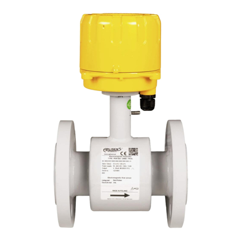
The electromagnetic flow meter PEM-1000 comprises the converter and the measuring
sensor. In the compact version the converter placed in the aluminum housing is embedded
directly on the sensor. In the remote version the converter is mounted using the assembly
equipment to the pipe or flat surface.
Figure 1. The flow meter PEM-1000ALW. The compact version

IO.PEM-1000(ENG)
10 02.A.003
Figure 2. The flow meter PEM-1000NW. The remote version.
6.3.1. The sensor design
The housing of the sensor is made of non-magnetic material, welded with flanges and
fasteners. The insulating insert of the required properties is installed inside the pipe
(compatible with the medium type). The system of the electromagnet coils generating
the required magnetic field is mounted directly on the measuring pipe.
A pair of electrodes placed opposite to each other and passing through the lined measuring
pipe is made of stainless steel (standard) or of other electrically conductive materials
matched to the properties of the measured medium.
The electrical system of the sensor is welded in the steel housing with the internal wiring
lead.

IO.PEM-1000(ENG)
02.A.003 11
Figure 3. The flow meter sensor. Overall dimensions
Mechanical data of the sensor PN16
Dimensions [mm]
Weight
DN
PN
A
B
D1
D2
d
n
kg
10
16
150
or 200
153
90
60
14
4
2.5
15
155
95
65
14
4
2.5
20
160
105
75
14
4
3
25
167
115
85
14
4
3.5
32
180
140
100
18
4
5
40
185
150
110
18
4
6
50
200
191
165
125
18
4
7
65
209
185
145
18
4
8
80
224
200
160
18
8
9.5
100
250
245
220
180
18
8
12
125
276
250
210
18
8
15
150
300
305
285
240
22
8
20
200
350
375
340
295
22
12
36
250
400
430
405
355
26
12
58
300
500
487
460
410
26
12
70
350
542
520
470
26
16
85
400
600
615
580
525
30
16
100
450
657
640
585
30
20
120
500
750
715
650
33
20
160
600
870
840
770
36
20
190
700
700
927
910
840
36
24
260
800
800
1050
1025
950
39
24
350
900
900
1145
1125
1050
39
28
450
1000
1000
1285
1255
1170
42
28
550
Table 1. Mechanical data of the sensor –PN 16

IO.PEM-1000(ENG)
12 02.A.003
Mechanical data of the PN 25 sensor
Dimensions [mm]
Weight
DN
PN
A
B
D1
D2
d
n
kg
10
25
150
or 200
153
90
60
14
4
2.5
15
155
95
65
14
4
2.5
20
160
105
75
14
4
3
25
167
115
85
14
4
3.5
32
180
140
100
18
4
5
40
185
150
110
18
4
6
50
200
191
165
125
18
4
7
65
209
185
145
18
4
8
80
224
200
160
18
8
9.5
100
250
245
235
190
22
8
12
125
276
270
220
26
8
15
150
300
305
300
250
26
8
20
200
350
375
360
310
26
12
36
250
400
430
425
370
30
12
58
300
500
487
485
430
30
16
70
350
542
555
490
33
16
85
400
600
615
620
550
36
16
100
450
657
670
600
36
20
120
500
750
730
660
36
20
160
600
870
845
770
39
20
190
700
700
927
960
875
42
24
260
800
800
1050
1085
990
48
24
350
900
900
1145
1185
1090
48
28
450
1000
1000
1285
1320
1210
56
28
550
Table 2. Mechanical data of the sensor –PN 25
Mechanical data of the PN 40 sensor
Dimensions [mm]
Weight
DN
PN
A
B
D1
D2
d
n
kg
10
40
150
or 200
153
90
60
14
4
2.5
15
155
95
65
14
4
2.5
20
160
105
75
14
4
3
25
167
115
85
14
4
3.5
32
180
140
100
18
4
5
40
185
150
110
18
4
6
50
200
191
165
125
18
4
7
65
209
185
145
18
4
8
80
224
200
160
18
8
9.5
100
250
245
235
190
22
8
12
125
276
270
220
26
8
15
150
300
305
300
250
26
8
20
200
350
375
375
320
30
12
36
250
400
430
450
385
33
12
58
300
500
487
515
450
33
16
70

IO.PEM-1000(ENG)
02.A.003 13
350
542
580
510
36
16
85
400
600
615
660
585
39
16
100
450
657
685
610
39
20
120
500
750
755
670
42
20
160
600
870
890
795
48
20
190
Table 3. Mechanical data of the sensor –PN 40
6.3.2. Electrodes
The material of the flow meter electrodes should be matched according to its chemical
resistance to the liquid in which the electrodes are immersed.
The cleanliness of the electrodes may affect the precision of the measurement, and
the accumulation of the impurities may have impact on the measurement process
(isolation form the liquid).
The cleaning of the electrodes is conducted together with the cleansing of the pipeline.
Any damage to the liner must be avoided.
The electrodes must be cleansed directly after the delivery, right before
the installation.
For most liquids, the electrodes do not require cleansing throughout the entire service
period, the self-cleaning by the flowing liquid is sufficient. Self-cleaning is particularly
effective at the flow speed of about 3m/s.

IO.PEM-1000(ENG)
14 02.A.003
6.3.3. The converter design
The electronic module of the converter is placed in a solid aluminum housing. The housing
has two screwed-off covers. The cover with a glass pane allows for the permanent, local data
view on the display. The unscrewing of the lid enables the access to the three buttons of
the local device operation.
The unscrewing of the cover located opposite to the glass pane secures the access to
the connecting terminals (see: p.8.1).
Figure 4. Converter of the flow meter PEM-1000 with the mounting bracket. Overall dimensions
Figure 5. Mounting bracket. Overall dimensions

IO.PEM-1000(ENG)
02.A.003 15
6.4. Identification markings
Each converter is equipped with the rating plate containing the following data:
1. Logotype or name of the manufacturer;
2. The marking of the flow meter;
3. Product code;
4. CE Marking;
5. Serial number;
6. Maximum flow –Qmax;
7. Supply parameters;
8. Output signal;
9. IP class according to EN 60529;
10.Year of manufacture;
11."Caution" Symbol. See important information contained in the service manual,
12.The information symbol concerning dealing with used equipment.
Each sensor is equipped with a plate containing the following data:
1. Logotype or name of the manufacturer;
2. CE Mark
3. Product code
4. Name and type of the sensor
5. Nominal diameter DN
6. Serial number of the sensor;
7. Year of manufacture;
8. Maximum pressure;
9. Liner material;
10.IP class according to EN 60529;
11."Caution" Symbol. See important information contained in the service manual;
12.Marking of flow direction.

IO.PEM-1000(ENG)
16 02.A.003
7. ASSEMBLY
7.1. General recommendations
Sensor of the electromagnetic flowmeter can be installed in any position in
accordance with the requirements but in case of vertical installation axis of
the electrodes should be always horizontal.
Entire space inside the sensor should be filled with the measured liquid during
the measurements.
It is recommended to ensure that direction of flow is consistent with direction of
the arrow on cover of the sensor; converter is factory set for operation in
this direction. It is possible to reverse direction of flow on operating device but
then also direction of flow in converter parameters should be changed.
It needs to be checked before the assembly whether there is enough space at
the flange to mount the flow meter using the available screws and nuts.
To avoid the influence on the vibration measurement as well as on the deflection
installation, the piping system must be fixed on both sides of the flow meter.
If the flow meter is installed on the pipeline with an greater inside diameter,
a reducer must be applied to ensure the axial fastening without the increase of
stress in pipes and flanges of the sensor.
During installation the straight sections should be of nominal diameter of
the sensor (DN) with lengths of at least 5DN before and 3DN after the sensor.
When installing the sensor on an insulated pipe (e.g. glass, plastics etc.) please
insulate the system with earthing rings connected with ground terminal of
the sensor - (fig. 15).
Conductive connection between ground (enclosure) of the sensor and liquid is
necessary for correct measurements.
It is essential to assemble the seal on both sides of the earthing ring during
the installation. It must be ascertained that no element of the seal is not included
in the clearance of the pipeline, as it may generate turbulence and disturb
the flow meter operation.
i

IO.PEM-1000(ENG)
02.A.003 17
Free outflow-
zero flow (no water)
Air bubbles are collected
in the sensor
Free inflow/outflow
Locate the sensor in
“siphon trap”
>5m
If vertical pipeline longer than 5m
downstream the sensor, install
deaerating valve (underpressure)
7.2. Recommended assembly method for the sensor
Figure 6. Recommended assembly method for the sensor
To avoid metrological errors caused by air bubbles or liner damage, consider the following
recommendations:
- During the assembly set the sensor properly, tighten the screws of the flanges, placed
opposite each other, evenly one after another.
- The properly selected seal of the flanges ensures better effect than the excessive
compressive force which may deform the flanges.
- The sensor should be mounted on the pipe to guarantee the axis of the measuring
electrodes of the sensor to be always horizontal.
- Teflon liner requires particular attention during servicing and assembly. During
the installation process the excessive negative pressure in the pipeline should be
avoided. The stub-ups of the liner to the external surfaces of the flanges on both sides
of the sensor must not be damaged. The sensors are supplied by the manufacturer
containing special covers, which prevent deformation of the Teflon liner. The covers
must be removed directly before the assembly, right before the insertion between the
counter flanges.
- Seal –the part of the liner extended to the external surfaces of flanges fails to function
as a seal, hence it must be placed between the flanges of the sensor and the pipeline.
The seal protruding inside the pipe generates the flow turbulence and reduces
the accuracy of measurements.
The recommended location near
the riser shaft
Recommended
location
No liquid
The plumbing trap ensures the
complete filling of the pipe
Air in
sensor
With the level decrease >5m the
soil vent pipe must be applied

IO.PEM-1000(ENG)
18 02.A.003
7.3. Assembly of the compact version of the converter
Figure 7. Assembly of the flow meter PEM-1000ALW –examples.

IO.PEM-1000(ENG)
02.A.003 19
7.4. Assembly of the remote version of the flow meter
Figure 8. Assembly of the flow meter PEM-1000NW –examples

IO.PEM-1000(ENG)
20 02.A.003
8. CONNECTION
All connection and installation activities must be performed with
the disconnected power supply as well as other external voltages, if such are
applied.
Within close proximity to the converter of the flow meter (in the same room)
the protected power switch must be mounted on the power supply line of
the flow meter. It should be easily accessible and marked in a way which is
distinct and in accordance with symbols complying with local electrical device
safety regulations.
Figure 9 Stub-ups of electrical cables from the converter of the flow meter PEM-1000.
The signal cable
plug of the sensor
Cable
signal from the sensor
Output cable
4…20mA
Power cable
230V (or 10-36V DC
as an option)
Table of contents
Other Aplisens Measuring Instrument manuals

Aplisens
Aplisens PMS-970 User manual

Aplisens
Aplisens WW-30Pt User manual

Aplisens
Aplisens SGE-25.SMART User manual

Aplisens
Aplisens SGE-25 User manual

Aplisens
Aplisens PEM-500 User manual

Aplisens
Aplisens WW-30 User manual

Aplisens
Aplisens CS-27/W User manual

Aplisens
Aplisens SGE-25.Modbus User manual

Aplisens
Aplisens PMS-620N User manual

Aplisens
Aplisens SGE-25.SMART User manual