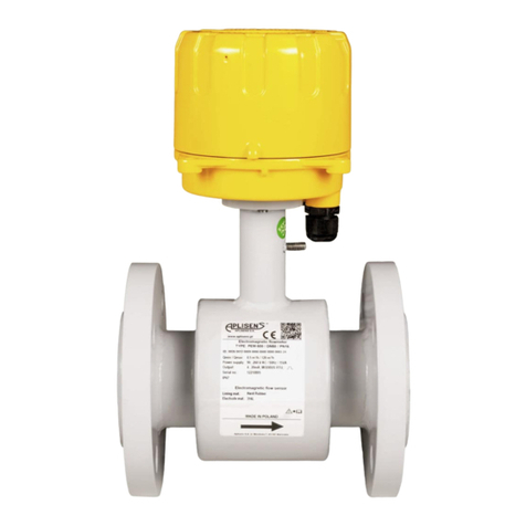
Aplisens PEM-1000ALW User manual

Symbols used
Symbol
Description
Warning to proceed strictly in accordance with the information contained in the doc-
umentation in order to ensure the safety and full functionality of the device.
Information particularly useful during installation and operation of the device.
Information on disposal of used equipment.
BASIC REQUIREMENTS AND SAFE USE
The manufacturer will not be liable for damage resulting from incorrect installation,
failure to maintain a suitable technical condition of the device or use of the device
other than for its intended purpose.
Installation should be carried out by qualified staff having the required authoriza-
tions to install electrical and I&C equipment. The installer is responsible for perform-
ing the installation in accordance with manual as well as with the electromagnetic
compatibility and safety regulations and standards applicable to the type of installa-
tion.
In systems with I&C equipment, in case of leakage, there is a danger to staff due to
the medium under pressure. All safety and protection requirements must be ob-
served during installation, operation and inspections.
If a malfunction occurs, the device should be disconnected and handed over to the
manufacturer for repair.
In order to minimize the risk of malfunction and associated risks to staff, the device
is not to be installed or used in particularly unfavourable conditions, where the fol-
lowing hazards occur:
−possible mechanical impacts, excessive shocks and vibration;
−excessive temperature fluctuation;
−water vapour condensation, dusting, icing.
Changes made to the manufacturing of products may be introduced before the paper version of the
manual is updated. The up-to-date manuals are available on the manufacturer’s website:
www.aplisens.com.

EN.IO.PEM.1000
Revision 02.A.004/2021.06 3
TABLE OF CONTENTS
1. INTRODUCTION ......................................................................................... 5
1.1. Trademarks ...........................................................................................................................5
2. SAFETY ...................................................................................................... 5
3. TRANSPORT AND STORAGE ................................................................... 6
3.1. Delivery check .......................................................................................................................6
3.2. Transport...............................................................................................................................6
3.3. Storage..................................................................................................................................6
4. GUARANTEE.............................................................................................. 6
5. IDENTIFICATION........................................................................................ 7
5.1. Manufacturer’s address .........................................................................................................7
5.2. Flowmeter identification.........................................................................................................7
5.3. CE mark, declaration of conformity........................................................................................8
6. INSTALLATION .......................................................................................... 9
6.1. General recommendations.....................................................................................................9
6.2. Recommended installation methods for flow sensor ..............................................................9
6.3. Installation of the PEM-1000 flowmeter................................................................................11
7. ELECTRICAL CONNECTION ................................................................... 13
7.1.1. Connecting the sensor signal cable..............................................................................14
7.2. Grounding............................................................................................................................16
Marking of the connection point of the functional earth of the flowmeter........................................16
7.2.1. Connecting of the transmitter with the option of using local HART communication.......16
7.2.2. Functional grounding....................................................................................................17
8. START-UP ................................................................................................ 19
9. TECHNICAL PARAMETER....................................................................... 19
9.1. Protection class ...................................................................................................................19
9.2. Technical specification.........................................................................................................19
9.3. Technical specification.........................................................................................................20
9.4. Metrological parameters ......................................................................................................20
9.5. Table of volumetric flows calculated for the characteristic flow velocities of the medium for
versions with flanges according to DIN................................................................................21
9.5.1. Selection of flowmeter diameter and measuring range.................................................22
10.MAINTANANCE........................................................................................ 24
10.1. Periodic inspections.............................................................................................................24
10.2. Non-periodic inspections......................................................................................................24
10.3. Cleaning/Washing................................................................................................................24
11.TROUBLESHOTING................................................................................. 25
11.1. Measurement board error E_FE_xx.....................................................................................25
11.2. Sensor error E_SENS_xx ....................................................................................................26
12.SCRAPING, DISPOSAL............................................................................ 26
13.HISTORY OF REVISIONS......................................................................... 26
APPENDIX A –Configuration Local MENU Settings................................... 27
APPENDIX B - Structure of the local MENU ................................................ 35

EN.IO.PEM.1000
4 Revision 02.A.004/2021.06
LIST OF DRAWINGS
Figure 1. Recommended examples of sensor installation....................................................................9
Figure 2. Examples of incorrect sensor installation on the site and suggested solutions. ..................10
Figure 3. Installation of the PEM-1000 flowmeter - examples............................................................11
Figure 4. Examples of installation of the flowmeter transmitter in the PEM-1000NW version on a pipe
and on the wall...................................................................................................................................12
Figure 5. Electrical wiring from the PEM-1000 transmitter.................................................................13
Figure 6. View of electrical terminals of the PEM-1000 flowmeter.....................................................13
Figure 7. Marking the leads of the sensor cable cores.......................................................................15
Figure 8. Connection pins of the sensor cable plug...........................................................................15
Figure 9. Location and method of connecting the protective earth to the transmitter housing............16
Figure 10. Proper preparation of the power cable..............................................................................16
Figure 11. Example of a functional earthing connection for a metal pipeline and for an insulated
pipeline using earthing rings. .............................................................................................................17
Figure 12.The way of connecting the functional ground to the transmitter housing...........................17
Figure 13.The method of connecting functional ground to the sensor housing.................................18
Figure 14. Graph of correct functional grounding of the PEM-1000 flowmeter...................................18
Figure 15. Recommended flow values of the PEM-1000 flowmeter...................................................22
Figure 16. The measuring range of the flowmeter is determined by the Qmax parameter.................23
LIST OF TABLES
Table 1. Symbols appearing on the flowmeter's nameplate.................................................................7
Table 2. Symbols appearing on the sensor's nameplate......................................................................8
Table 3. Designation of connection terminals of the PEM-1000 flowmeter.........................................14
Table 4. Connection pins of the sensor cable plug.............................................................................15
Table 5. Technical data of the sensor and transmitter. ......................................................................19
Table 6. Flow values for the PEM-1000 flowmeter.............................................................................20
Table 7. Volumetric flow as a function of the linear velocity of the medium........................................21
Table 8. Flow values corresponding to a speed of 1 m/s. ..................................................................22
Table 9.Error descriptions of the PEM-1000 flowmeter and their possible solutions..........................25

EN.IO.PEM.1000
Revision 02.A.004/2021.06 5
1. INTRODUCTION
The subject of manual are electromagnetic flowmeters in two versions:
−A compact version designated PEM-1000ALW - with transmitter placed directly on the meas-
uring sensor;
−A remote version designated PEM-1000NW - with transmitter connected via cable and placed
up to 50 m from measuring sensor.
The manual contains data, guidelines and recommendations concerning installing and operating, as
well as procedure in the event of a failure.
The description of device configuration can be found in the EN.IK.PEM-1000 configura-
tion manual, and the Modbus communication is described in the IM.PEM-1000(ENG).
They are available on the manufacturer's website www.aplisens.com
1.1. Trademarks
Modbus®is a service registered and managed by SCHNEIDER AUTOMATION, INC..
2. SAFETY
−The installation and start-up of the device and any activities related to operation shall be
carried out after thorough examination of the contents of user’s manual and the instruc-
tions related thereto;
−installation and maintenance should be carried out by qualified staff having the required
authorizations to install electrical and measuring devices;
−the device shall be used according to its intended purpose in line with the permissible
parameters specified on the nameplate (➔Flowmeter identification);
−the protection elements used by the manufacturer to ensure transmitter safety may be
less effective if the device is operated in a manner not consistent with its intended pur-
pose;
−before installing or disassembling the device, it is absolutely necessary to disconnect it
from the power source;
−no repairs or alterations to the transmitter electronic system are permitted. Assessment
of damages and possible repair may only be performed by the manufacturer or author-
ized representative;
−do not use instruments if damaged. In case of malfunction, the device must be put out of
operation;

EN.IO.PEM.1000
6 Revision 02.A.004/2021.06
3. TRANSPORT AND STORAGE
3.1. Delivery check
After receiving the delivery of the equipment, it is necessary to:
−make sure that the packaging and its contents were not damaged during transport;
−check the completeness and correctness of the received order, and make sure no parts are
missing.
3.2. Transport
Transport of flowmeters shall be carried out with the use of covered means of transport, in original
packages. The packaging shall be protected against movement and direct impact of atmospheric fac-
tors.
3.3. Storage
Flowmeters shall be stored in a factory packaging, in a room without vapours and aggressive sub-
stances, protected against mechanical impact.
Allowable range of ambient and storage parameters:
Allowable range of ambient/storage temperature
-20 … 60ºC (-4 … 140°F)
Relative humidity
to 80%
Surrounding atmosphere
No aggressive ingredients
Height above sea level
to 2000 m
The permissible ambient and device operating parameters must not be exceeded. Exceeding
them may result in an increase in measurement errors.
4. GUARANTEE
General terms and conditions of guarantee are available on the manufacturer's website:
www.aplisens.com/ogolne_warunki_gwarancji
The guarantee shall be repealed if the device is used against its intended use, failure to
comply with user’s manual or interference with the structure of the device.

EN.IO.PEM.1000
Revision 02.A.004/2021.06 7
5. IDENTIFICATION
5.1. Manufacturer’s address
APLISENS S.A.
03-192 Warsaw
Morelowa 7 St.
Poland
5.2. Flowmeter identification
Table 1. Symbols appearing on the flowmeter's nameplate.
Logo and name of manufacturer.
CE mark.
Manufacturer’s address.
Flowmeter type .
Min/Max of flow value.
Supply voltage values.
Output signal.
Serial number of flowmeter.
Serial number of sensor.
Year of production.
IP protection rating.
Note about the obligation to read the manual.
Information on dealing with used equipment.

EN.IO.PEM.1000
8 Revision 02.A.004/2021.06
Table 2. Symbols appearing on the sensor's nameplate.
Logo and name of manufacturer.
CE mark.
Sensor type.
Serial number of sensor.
Year of production of the sensor.
Sensor lining.
Electrode material.
IP protection rating.
,
Value of calibration coefficient A and B.
Information on dealing with used equipment.
Note about obligation to read the manual.
Direction flow of medium.
Manufacturer’s address.
5.3. CE mark, declaration of conformity
The device has been designed to meet the highest safety standards, has been tested and has left the
factory in a condition that is safe for operation. The device complies with the applicable standards and
regulations listed in the EU Declaration of Conformity and has CE marking on nameplate.

EN.IO.PEM.1000
Revision 02.A.004/2021.06 9
6. INSTALLATION
6.1. General recommendations
-It is recommended that the flow direction is in the direction of the arrow on the sensor,
the transducer is also factory set to work in this direction. The flow in the opposite direction to
the arrow is shown as a negative value. If it is necessary to mount the sensor upside down,
please contact the manufacturer.
-Before installation, check if there is enough space next to the flange for installing the flow
meter with the use of bolts and nuts.
-During the measurement, the entire space inside the sensor should be filled with the meas-
ured liquid.
-Fix the pipework on both sides of the flowmeter to avoid vibration and sag in the pipework from
affecting the measurement.
-If the flowmeter is installed in a pipeline with a larger ID, use a reducer that ensures axial fixa-
tion without increasing stress on the sensor pipes and flanges. Remember to keep straight
sections in front of and behind the sensor.
-During installation the straight sections should be of nominal diameter of the sensor (DN) with
lengths of at least 5DN before and 3DN after the sensor.
-When installing the sensor on an insulated pipe (e.g. glass, plastics etc.) please insulate
the system with earthing rings connected with ground terminal of the sensor ➔Figure 11.
-Conductive connection between ground (enclosure) of the sensor and liquid is necessary
for correct measurements.
-During assembly it is essential to install a seal between the flanges of the sensor and the
piping. When using grounding rings, seal use rings on both sides.
-Do not use gaskets made of hard materials as they may damage the Teflon lining or, in the
case of rubber lining, fail to ensure a sufficient tightness of the installation.
-Make sure that no sealing element enters the lumen of the pipeline as this may introduce
turbulence into the flow and disrupt the operation of the flowmeter.
6.2. Recommended installation methods for flow sensor
Figure 1. Recommended examples of sensor installation.

EN.IO.PEM.1000
10 Revision 02.A.004/2021.06
To avoid metrological errors caused by air bubbles or damage floor covering, follow the recommenda-
tions below:
-during installation, properly position the sensor, tighten the flange bolts simultaneously on both
sides;
- it is recommended that the flowmeter is installed so that the electrode axis is as horizontal as
possible, in accordance with the examples ➔Figure 3. Installation of the PEM-1000 flowme-
ter - examples.
- Teflon lining requires special care during handling and assembly. During installation (opera-
tion), avoid excessive under pressure in the pipeline. Do not damage liner leads to the outer
flange surfaces on both sides of the sensor. Some sensors are delivered from the manufactur-
er with special covers that prevent the deformation of the Teflon lining. Covers should be re-
moved immediately before installation, before placing between the counter flanges;
- ensure that no seal element enters the lumen of the pipeline, as this may introduce turbulence
into the flow and disturb the flowmeter.
A
B
Figure 2. Examples of incorrect sensor installation on the site and suggested solutions.
The figure shows the two most common cases of incorrect installation of a flowmeter sensor on
a facility.
Case A shows incorrect installation of the pump (behind the sensor). This type of mounting can cause
This type of mounting can cause distortion of the flow values and also expose the electrodes, which
can result in an error of empty pipe detection. In extreme cases the vacuum generated by the pump
can damage the sensor lining.
Case B shows the sensor mounted at the end of the pipeline. This way of mounting may cause This
type of mounting can cause the electrodes to be exposed, which will result in a distortion of the flow,
as well as the ingress of air and drying up of the medium on the inner walls of the sensor. In order to
avoid problems with the functioning of the device, it is recommended to use a siphon as shown in the
picture.

EN.IO.PEM.1000
Revision 02.A.004/2021.06 11
6.3. Installation of the PEM-1000 flowmeter
Figure 3. Installation of the PEM-1000 flowmeter - examples.
It is recommended to install the flowmeter in a horizontal position (A), with the possibility
of tilting it by about 30° (B) and in a vertical position (C) - according to the examples
shown in the figure. Otherwise there is a possibility of disturbing the measurements or
issuing an alarm of empty pipe detection when there is air in the system (one of the elec-
trodes will be uncovered).

EN.IO.PEM.1000
12 Revision 02.A.004/2021.06
Figure 4. Examples of installation of the flowmeter transmitter in the PEM-1000NW version on a pipe and on
the wall.

EN.IO.PEM.1000
Revision 02.A.004/2021.06 13
7. ELECTRICAL CONNECTION
All connection and assembly operations must be performed with the supply voltage and
other external voltages, if used, disconnected. In the close vicinity of the flowmeter trans-
ducer (in the same room) In the close vicinity of the flowmeter transducer (in the same
room), install a circuit breaker on the flowmeter supply line with protection. It should be
easily accessible and clearly and unambiguously marked with symbols complying with local
regulations for safety of electrical equipment.
Figure 5. Electrical wiring from the PEM-1000 transmitter.
Electrical terminals of the flowmeter can be accessed by unscrewing the side cover of the
side cover of the transmitter casing. The figure and table below show the arrangement and purpose of
the individual terminals.
Figure 6. View of electrical terminals of the PEM-1000 flowmeter.

EN.IO.PEM.1000
14 Revision 02.A.004/2021.06
Table 3. Designation of connection terminals of the PEM-1000 flowmeter.
Terminal No
Description
Power supply
1
mains supply
(-)
Low voltage power
supply DC (option)
2
(+)
Binary output 1
3
Any polarization
Galvanically isolated, passive
4
Pulse output/
frequency
5
passive
any polarization, galvanically isolated
6
Analog current
output 4÷20 mA
7
(+)
active / passive
(default active)
8
(-)
Communication
9
RS 485 A
port galvanically isolated, ground
should be connected
10
RS 485 B
11
RS 485
ground/shield
Binary input
passive
12
Any polarisation
galvanically isolated
13
Binary output 2
14
Any polarisation, galvanically isolated
passive
15
In order to maintain security of the supply lines and output lines should be carried within the
housing separate glands.
The cables (lines) attached to the screw terminals should be terminated with end sleeves 0.75 mm2.
When connecting the flowmeter to the power supply, observe the following rules:
−connections of electrical appliances;
−protection against electric shock;
−principles of safe operation of electrical installations by personnel.
The electrical protection of the device allows it to be used in various environments, and in consultation
with the manufacturer, it is possible to make additional modifications that allow it to be used in specific
user environmental conditions. The output cables from the converter should not be led next to power
cables and other cables that may generate interference. Devices cooperating with the flowmeter
should be resistant to electromagnetic disturbances generated in the environment, in accordance with
the compatibility requirements in force in the place of use.
Power supply of the transducer with a low-voltage power supply (optional version) is con-
nected to the same POWER SUPPLY terminals as the mains power supply (plus terminal
no. 2). The low-voltage power supply is protected against incorrect power polarity. Do not
connect the mains power to the POWER SUPPLY terminals of the flowmeter in the version
with a low-voltage power supply, as this will damage it.
7.1.1. Connecting the sensor signal cable
The signals that are transmitted from the sensor electrode circuit to the transmitter have values at the
millivolt level. These signals are very sensitive to magnetic and electrostatic interference that can
come from adjacent high voltage cables, power cables and power lines feeding high power electrical
equipment. The interference is compensated for by the flowmeter's internal noise filter; nevertheless,
these unwanted signal sources should be avoided if possible. For the PEM-1000NW flowmeter it is
recommended to locate the signal cable from the sensor in separate cable ducts.
The signal cable coming out of the sensor has a special design and is part of the order, therefore its
length should not be changed (for a certified instrument it must not be changed).
The cable sheath (insulation) should remain intact along its entire length.

EN.IO.PEM.1000
Revision 02.A.004/2021.06 15
Figure 7. Marking the leads of the sensor cable cores.
Figure 8. Connection pins of the sensor cable plug.
Table 4. Connection pins of the sensor cable plug.
Socket number / PIN on the
plug
Cable core type
Colour of the cable
core
1
Cable outer shield or free clamp (depending on sen-
sor type)
-
2
Internal shield of the electrode pair
-
3
-
-
4
Electrode pair
White
5
Electrode pair
Brown
6
-
-
7
-
-
8
-
-
9
-
-
10
Internal screen of the coil pair
-
11
Coil pair
Green
12
Coil pair
Yellow
The wires of the sensor cable should be connected to the plug in accordance with the instructions in
Figure 10 and the PIN description in Table 2.
Incorrect connection of the cable cores to the transducer plug will cause many measure-
ment errors.

EN.IO.PEM.1000
16 Revision 02.A.004/2021.06
7.2. Grounding
The flowmeter must be earthed according to the rules in force at the place of installation.
The lack of functional grounding can cause significant disturbances in the
measurements.
Marking of the connection point of the functional earth of the flowmeter.
Marking of the protective ground connection in the transmitter housing.
7.2.1. Connecting of the transmitter with the option of using local HART communication
Protective grounding is an element ensuring safety against electric shock in ac-
cordance with the standards and must always be connected.
1. Screw M5.
2. Spring washer M5.
3. Serrated washer
wg DIN 6797 J –M5.
4. The cable is terminated with a crimp terminal
with an eyelet M5.
5. Housing.
Figure 9. Location and method of connecting the protective earth to the transmitter housing.
Use a power cable suitable for the cable gland, with certified cables with a working voltage
of 300/500 V.
Figure 10. Proper preparation of the power cable.
In order to maintain safety, the power cable should be prepared in such a way that the earth
wire (yellow-green) is longer than the other wires by min. 20mm. The end of the earthing
wire should be extended with a tip with an eyelet to the M5 screw. Crimp the end on the
earthing conductor with a cable crimper.

EN.IO.PEM.1000
Revision 02.A.004/2021.06 17
7.2.2. Functional grounding
Functional grounding ensures the equalization of the potentials of the transmitter, sensor,
pipeline and liquid, enabling the correct performance of measurements.
The transmitter housing should always be connected to the sensor housing and connected to the
sensor grounding point as shown in the figures below. This is particularly important when installing the
flowmeter in a remote version (NW). The grounding point of the sensor should be connected to the
metal pipeline or to the grounding rings in the case of non-conductive pipelines.
Metal pipeline
Insulated pipeline - grounding with the use of
grounding rings
Figure 11. Example of a functional earthing connection for a metal pipeline and for an insulated pipeline using
earthing rings.
To properly ground the flowmeter, refer to the graph in Figure 16.
Figure 12.The way of connecting the functional ground to the transmitter housing.
The sequence of elements in the properly made earth connection of the transmitter:
1. Screw M5.
2. Spring washer M5.
3. Serrated washer acc. DIN 6797 J –M5.
4. The cable is terminated with a crimp terminal with an eyelet M5.
5. Housing.

EN.IO.PEM.1000
18 Revision 02.A.004/2021.06
Connection elements in the order of assembly:
1. Screw M6.
2. The cable is terminated with a crimp terminal with
an eyelet M6.
3. Serrated washer acc. DIN 6797 J –M6.
4. Spring washer M6.
5. Nut M6.
Figure 13.The method of connecting functional ground to the sensor housing.
Figure 14. Graph of correct functional grounding of the PEM-1000 flowmeter.

EN.IO.PEM.1000
Revision 02.A.004/2021.06 19
8. START-UP
After assembly and electrical connection of the flowmeter must be checked installation and connec-
tions as follows:
-tighten all cable connections, terminals and plugs in all connectors and verify the earth connection;
-verify the correctness of the electric supply in accordance with the information on the rating plate of
the device;
-verify the installation's protection against electric shock;
-check the correct installation of the flowmeter in the pipeline (no play, gaps);
-if no defects or damage are found in the installation, fill the pipeline with liquid and verify its tightness.
After a short flushing, switch the system on-off-on and start the measurement.
The description of the device configuration can be found in the EN.IK.PEM-1000 manual,
and the description of Modbus communication in the IM.PEM-1000(ENG) manual.
The documentation is available on the manufacturer's website www.aplisens.com
9. TECHNICAL PARAMETER
9.1. Protection class
The device has protection class I, a protective conductor has been led out and connected inside the
housing. The measuring circuits (to the sensor) are separated from hazardous voltages by reinforced
insulation in accordance with the requirements of PN-EN 61010-1.
9.2. Technical specification
Table 5. Technical data of the sensor and transmitter.
Technical data
Transmitter
Sensor
Electrical conductivity of the medium 5 µS/cm
Nominal size DN 10…1000, (ANSI 0.5”…40”)
Input resistance 1010
Max static pressure Standard 1,6 MPa (2,5 MPa, 4 MPa)
Accuracy* 0,5% of reading at 20…100% Qmax
1% of reading at 10…20% Qmax
Process connection Flange DIN ANSI
Low flow rejection Adjustable value
Ambient temperature -20…60C
Actual flow both directions (l/s, m3/h, m3/s, other)
Liner temperature range Rubber: -5…90C
Teflon: -25…130C
Totalizer 3 counters, total, positive, negative (m3, other)
Low flow alarm Adjustable, any value
Connection cable Standard 8m (other on request)
Configuration LCD display/buttons or Modbus RTU via RS485
Electrodes material Stal 316L
(Hastelloy, Tantal, Titan, Platin)
Empty pipe detection Cyclic, configurable
Analog output 4…20 mA/500
Active output (passive –on request)
Flow tube material Stal 321
Pulse/frequency output Max. 24 V/10mA DC;
0,1…2000 Hz in frequency mode;
up to 500Hz in pulse mode.
Insulation lining Hard rubber DN20…1000
Teflon DN10…500
Halar ECTFE DN350…600
2-state output OC 2; open collector Max. 35 V DC for each
galvanic insulation; reverse polarity protection
Casing and flange material Carbon steel
(steel 304,steel 321)
Communication output Modbus RTU/RS 485
Galvanic insulation
Corrosion protection Acrymetal varnish
2-state input 5…35 V DC/2 mA
Passive input, galvanic insulation, reverse polarity protection
Accessories Grounding rings
Power supply 90…260 V AC/ 50Hz/15 VA
10…36 V DC / 15W (reverse polarity protection)
Excitation coils supply From the transmitter
Excitation of coils isolation class E
IP range IP66 (IP67-on request)
Protection class IP67 (IP68-on request)
Ambient temperature -20…60C
Measuring principle Electromagnetic
Execution on request of sensor Stainless steel
Hygienic connection
Weight 3,5 kg
Weight acc. to data in the catalogue
i

EN.IO.PEM.1000
20 Revision 02.A.004/2021.06
9.3. Technical specification
Flow
0,3 –12 m/s
Measured medium
Water 10 –30ºC
Conductivity
> 300 µS/cm
Supply variability
Un ± 2% (Un – power supply voltage)
Ambient temperature
18 - 25ºC, constant humidity
Stabilization time after switching
on power
Min. 20 min
Straight flow sections
5DN in front of the sensor, 3DN behind the sensor
Measuring sensor
Combined with the transmitter, positioned centrally under with the guide-
lines contained in the manual
ATTENTION! Reference conditions generally contain reference values or reference ranges for influencing quan-
tities that affect the flowmeter.
9.4. Metrological parameters
The PEM-1000 flowmeter is made in the range of the size of flange connections defined by the DIN
standard in the range of DN10 ÷ DN1000 or, optionally, in the size range of flange connections
according to the ANSI, BS standard. Standard flow rates for individual versions of the flowmeter with
flange connections according to DIN in the range DN10 ÷ DN1000 are presented in the table below.
It is possible to set other values of the Qmax flow for individual versions of the flowmeter.
Table 6. Flow values for the PEM-1000 flowmeter.
Flow values
DN acc.
DIN
Recommended
flow limits
Factory settings
~Q(min)
~Q(max)
Analog output 4…20 mA
Pulse output
Low flow cut-
off (v~0,1
[m/s])
Measuring
range
Linear flow velocity
(to the end of the
measuring range)
Volume/
pulse
Number of
pulse / m3
[m3/h]
[m3/h]
[m3/h]
[m/s]
[m3/impulse]
[m3/h]
10
0,08
2,8
0÷1
3,54
0,0000025
400000
0,03
15
0,19
6,4
0÷2
3,14
0,000005
200000
0,06
20
0,34
11
0÷4
3,54
0,00001
100000
0,12
25
0,5
18
0÷5
2,83
0,0000125
80000
0,15
32
0,9
29
0÷10
3,45
0,000025
40000
0,3
40
1,4
45
0÷15
3,32
0,00004
25000
0,45
50
2,1
71
0÷20
2,83
0,00005
20000
0,6
65
3,6
119
0÷30
2,51
0,0001
10000
0,9
80
5
181
0÷50
2,76
0,000125
8000
1,5
100
8
283
0÷100
3,54
0,00025
4000
3
125
13
442
0÷150
3,40
0,0004
2500
4,5
150
19
636
0÷200
3,14
0,0005
2000
6
200
34
1131
0÷360
3,18
0,001
1000
10,8
250
53
1767
0÷500
2,83
0,00125
800
15
300
76
2545
0÷760
2,99
0,002
500
22,8
350
104
3464
0÷1000
2,89
0,0025
400
30
400
136
4524
0÷1300
2,87
0,004
250
39
500
212
7069
0÷2000
2,83
0,005
200
60
600
305
10179
0÷3000
2,95
0,008
125
90
800
416
13854
0÷5000
2,76
0,0125
80
120
1000
848
28274
0÷8000
2,83
0,025
40
240
This manual suits for next models
1
Table of contents
Other Aplisens Measuring Instrument manuals

Aplisens
Aplisens SGE-25 User manual

Aplisens
Aplisens SGE-25.SMART User manual

Aplisens
Aplisens WW-30Pt User manual

Aplisens
Aplisens SGE-25.Modbus User manual

Aplisens
Aplisens PMS-970 User manual

Aplisens
Aplisens SGE-25.Modbus User manual

Aplisens
Aplisens SGE-25.SMART User manual

Aplisens
Aplisens PMS-620N User manual

Aplisens
Aplisens PEM-500 User manual

Aplisens
Aplisens MS-100K User manual