Product
Specifications
Accessories
Driver Complement:
Low Frequency:Dual Apogee 15" (381mm) permanent magnet cone-type drivers are
treated with Ferrofluid®and a waterproofing compound, providing resistance to moisture
and enabling long-term stability of cone resonance and cone mass parameters
Mid Frequency: Dual Apogee 10" (254mm) permanent magnet cone-type drivers are treat-
ed with Ferrofluid and a waterproofing compound, providing resistance to moisture and
enabling long-term stability of cone resonance and cone mass parameters
High Frequency:Three Apogee 2" (51 mm) throat compression drivers treated with
Ferrofluid for greater power handling capability, lower distortion, and control of short-term
impedance rise
Input Connectors:
Neutrik™ NL8MP Speakon™ connectors standard; Cannon EP series and gas-tight barrier
strips optional
Engineering Data:
Format:
Tri-amped/Three-way/Horn-loaded MF and HF/Electronically-coupled
Dispersion:
ALA-9W H: 90° x V: 10°
Frequency Response (1m on axis):
45 Hz to 17.5 kHz + 3dB
Max SPL (@1m):
136 dB cont./142 dB peak
PTML (peak transient mechanical limit):
153 dB
Sensitivity (1 W @ 1 m):
LF: 100 dB SPL MF: 108 dB SPL HF: 112 dB SPL
Nominal Impedance:
LF: 8ohms x 2MF: 4ohms HF: 4ohms
Max Power Handling:
LF: 1200 W cont./ 4800 W peak
MF: 600 W cont./ 2400 W peak
HF: 450 W cont./ 1800 W peak
Dimensions:
front: 47"(1194mm) W x 24"(610mm) H
rear: 47"(1194mm) W x 20.1"(511mm) H
depth: 22.7"(577mm)
Weight:
236 lb. (107 kg)
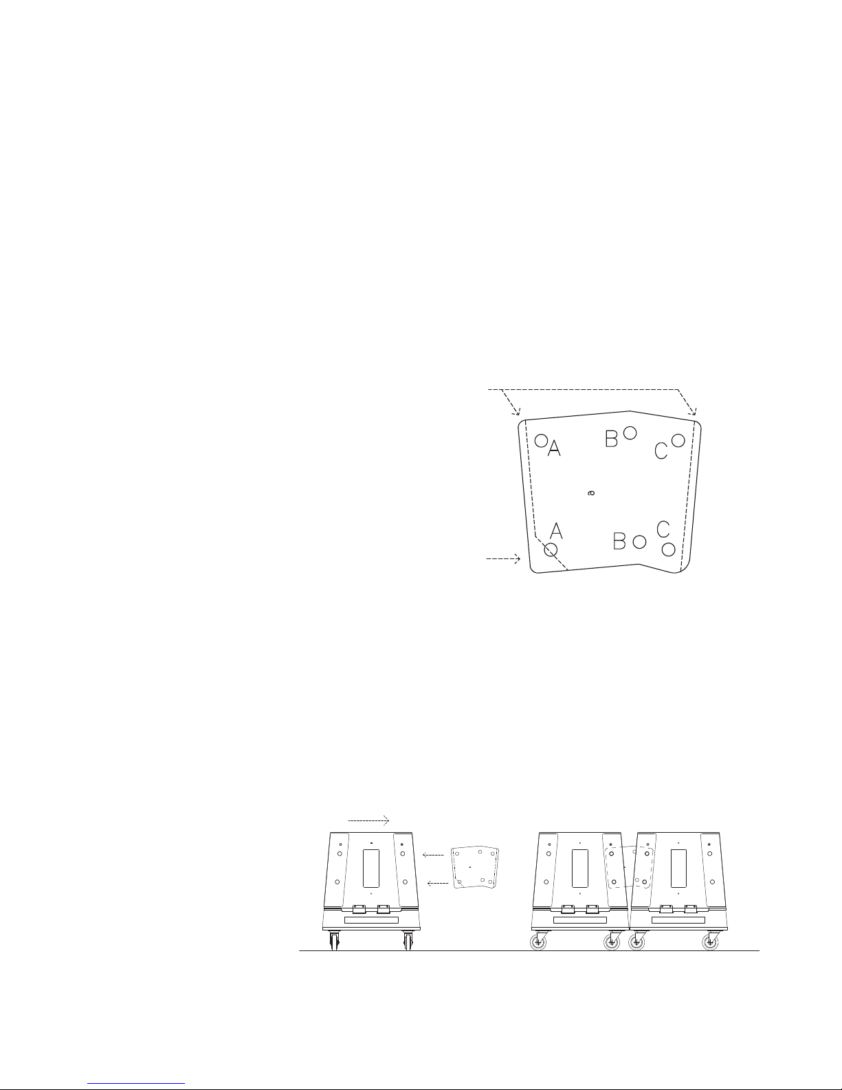
Optional Touring Package
Includes an ALA-9 Cordura cover and transport dolly.The ALA-9 fits,
grille down, on the dolly for easy, secure transport and grille protec-
tion. When not in use, the dollies can be stacked on top of one anoth-
er to save on storage space. The Cordura cover fits over both the
ALA-9 and dolly.
7