Apogee ALA-C1 User manual

©2020 Bogen Communications, Inc.
Specications are subject to change without notice.
740-00120C 2010
ALA-C1
Acoustic Line Array
Loudspeaker System
User Manual

Table of Contents
Introduction . . . . . . . . . . . . . . . . . . . . . . . . . . . . . . . . 2
Package Contents . . . . . . . . . . . . . . . . . . . . . . . . . . . 2
Important Safety Information . . . . . . . . . . . . . . . . . . 3
Mounting Instructions . . . . . . . . . . . . . . . . . . . . . . 3-7
Rigging Installation . . . . . . . . . . . . . . . . . . . . . . . . . 8-9
Frequency Response . . . . . . . . . . . . . . . . . . . . . . . 10
Polar Measurements . . . . . . . . . . . . . . . . . . . . . . . . 10
Electrical Connection Wiring Guide . . . . . . . . . . . 10
Technical Specications . . . . . . . . . . . . . . . . . . . . . 10
Warranty Information . . . . . . . . . . . . . . . . . . . . . . . . 11
1

2
Introduction
The Apogee ALA-C1 Acoustic Line Array Loudspeaker is a high-fidelity
70V/8-ohm, passive, 2-way xed column, all-weather loudspeaker. It provides
superb speech enhancement and music reproduction for small- to medium-sized
venues, such as school and civic auditoriums, community theaters, lecture halls,
and houses of worship. This system’s design offers broad horizontal dispersion
(140-degrees) and focused vertical dispersion (25-degrees), which is ideal for
uniform side-to-side coverage, while minimizing ceiling and oor reections that
could degrade intelligibility. Mounting is via an included bracket that allows for
vertical down tilt of 0-10-degrees.
Package Contents
The ALA-C1 System Package contents include:
• One (1) ALA-C1 Acoustic Line Array Loudspeaker User Manual
• One (1) ALA-C1 Acoustic Line Array Loudspeaker with
a pre-installed sliding mounting bracket
• One (1) ALA-C1 Wall Mount Kit

3
Mounting Instructions
Mounting is via an included wall-mount plate set that allows for vertical down
tilt of 0-, 5-, or 10-degrees. The ALA-C1 Loudspeaker has a pre-installed sliding
mounting bracket. The mounting bracket slides freely along a built-in bracket
channel on the rear of the speaker enclosure.
IMPORTANT SAFETY INSTRUCTIONS
Always follow these safety precautions when using or installing
the ALA-C1 Loudspeaker and accessories:
• Read and keep these instructions.
• Heed all warnings.
• Follow all instructions, particularly those pertaining to rigging,
mounting, hanging, and electrical connections.
• Only use accessories that are specied and approved by Bogen.
WALL-MOUNT PLATE A
WALL-MOUNT
FASTENERS
(NOT INCLUDED)
Figure 1, Installing Wall-Mount Plate A

4
1. Attach the Wall-Mount Plate A to the desired location on the wall using the
proper fasteners.
NOTE: Wall-Mount fasteners are NOT INCLUDED as mounting requirements vary
depending on the wall structure or surface.
Screws should be used in each of the four holes on the Wall-Mount Plate A
as shown in Figure 1 to ensure that the plate supports the entire weight of
the loudspeaker. The screws and the wall material/supporting structure
must support the entire speaker weight. Failure to do so could lead to an
unsafe mounting.
2. Slide the mounting bracket to the desired position on the back of the speaker.
The mounting bracket can be slid freely along the back of the speaker
enclosure. To prevent top-heavy installation, we recommend installing the
mounting bracket as high on the speaker as possible while still allowing you
to achieve the desired install angle.
NOTE: For 0- or 5-degree tilts, use the full range of the speaker enclosure. For a
10-degree tilt, we recommend sliding the bracket down to the built-in stop.
3. Use the four M4.7 self drilling screws and four M5 lock washers to secure
the mounting bracket to the speaker. Tighten each screw to 24-26 in-lbs.
MOUNTING INSTRUCTIONS (cont’d):
Figure 2, Securing Sliding Mounting Bracket
BUILT-IN STOPS
SLIDING MOUNTING BRACKETS
(4) M5 LOCK WASHER
(4) M4.7 x 15mm HEX-HEAD
SELF DRILLING SCREW
MOUNTING CHANNEL

5
4. Select the desired tilt knuckle.
NOTE: Two different tilt knuckles are included to provide the vertical focus angle
or optimal coverage. Use the tilt knuckle with sticker A for a 0-degree or a 10-degree
angle. Use the tilt knuckle with sticker B for a 5-degree angle. (See Figure 3.)
5. Bolt the selected tilt knuckle to the Wall-Mount Plate B using the three M6 x
14mm screws and lock washers included in the mounting kit. Tighten each
screw to 40-45 in-lbs. (See Figure 4.)
NOTE: Verify that the screws are securely tightened to the torque specs provided.
Failure to do so may result in an unsafe installation.
MOUNTING INSTRUCTIONS (cont’d):
KNUCKLE “A” HAS
A RECESSED TOP
KNUCKLE “B” HAS A
NON-RECESSED TOP
Figure 3, Selecting Tilt Knuckle
Sticker
A
Sticker
B
Figure 4, Installing Tilt Knuckle to Wall-Mount Plate B
WALL-MOUNT PLATE B
(3) M6 LOCK WASHER
(3) M6 x 14mm SOCKET
HEAD SCREWS
DESIRED
TILT KNUCKLE
THROUGH STEP 4

6
MOUNTING INSTRUCTIONS (cont’d):
WALL-MOUNT
PLATE B,
TILTED
10-DEGREES
6. Attach the two knuckle pieces together.
To have 0-degree installation, make
sure the Wall-Mount Plate B is parallel
to the speaker enclosure. Rotate the
top tilt knuckle one step clockwise to
obtain a 10-degree tilt. (See Figure 5.)
7. Secure both knuckle pieces using one M8 hex head screw and M8 lock
washer. Tighten the screw to 95-105 in-lbs.
WARNING
All fasteners must be securely tightened to keep the speaker in
position and ensure it is securely mounted. Failure to follow this
instruction may result in property damage, injury, death, and/or
legal liability to you and your company.
Figure 6, Securing Tilt Knuckle
NOTE: Make sure all parts are assembled in the order shown in Figure 6.
(1) M8 LOCK WASHER
(1) M8 x 40mm
HEX HEAD BOLT
WALL-MOUNT
PLATE B

7
8. Arrange the speaker so that Wall-Mount Plate B slides over the top of Wall-
Mount Plate A. The folded edges on the top side of the plates should line up.
9. Align the screw holes on the sides of Wall-Mount Plate A with those on Wall-Mount
Plate B and secure them using two M4 sheet metal screws with lock washers.
Tighten each screw to 18 in-lbs. (See Figure 7.)
MOUNTING INSTRUCTIONS (cont’d):
Figure 7, Hanging Loudspeaker
WALL-MOUNT PLATE B
WALL-MOUNT PLATE A
(2) M4 LOCK WASHER
(2) M4 x 16mm
METAL SHEET SCREW
ALIGN SET SCREW HOLES

8
Rigging Installation
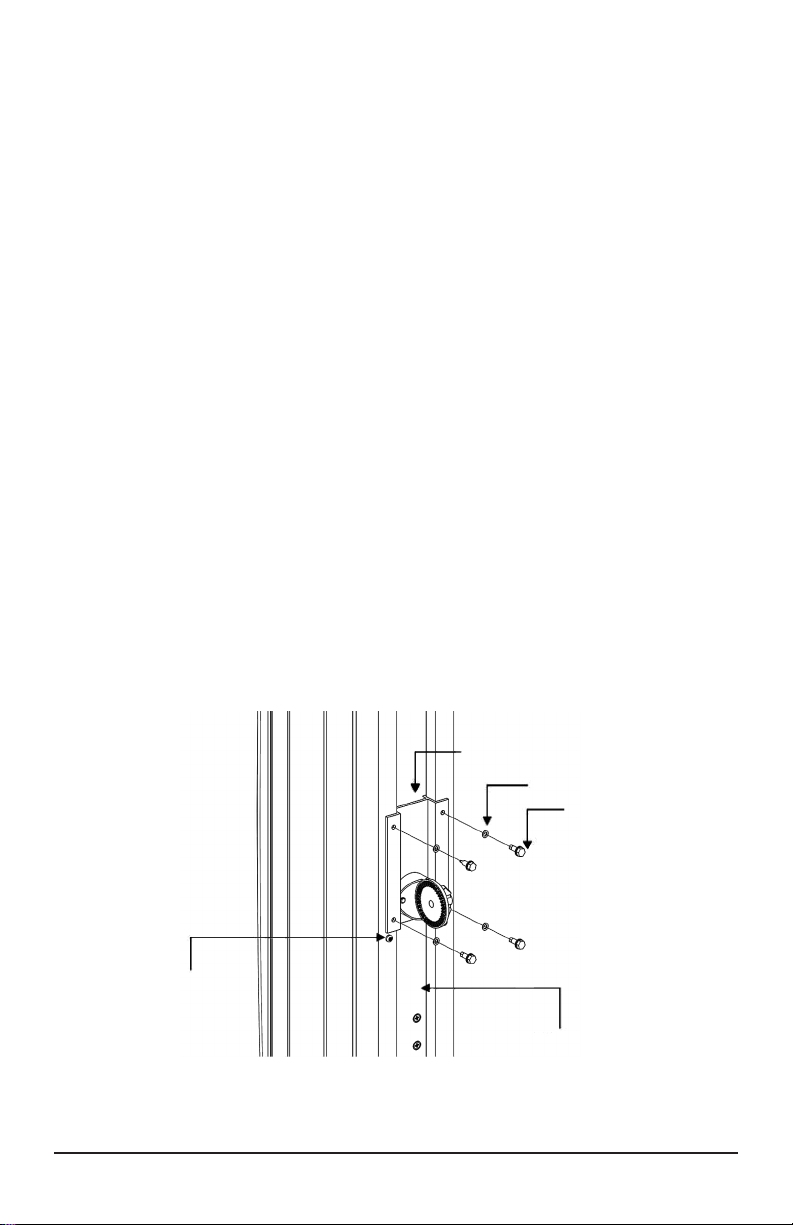
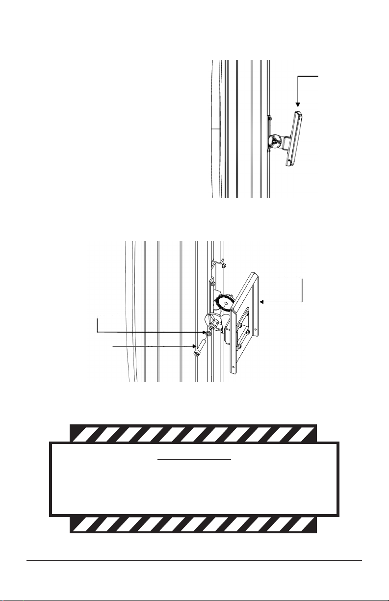
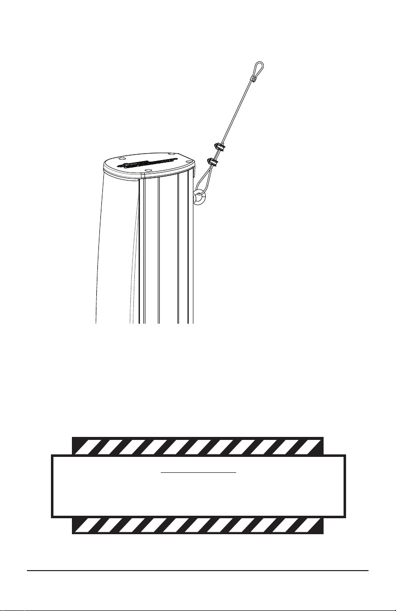
A safety cable (supplied) must be used whenever an ALA-C1 is mounted using
the supplied mounting bracket. The safety cable must be secured to a suitable
load-bearing point (not supplied) on the wall or ceiling. After nal positioning of
the loudspeaker, make sure that the cable is taut to minimize shock load in the
event of bracket failure.
WARNING
The loudspeaker described in this manual is designed and
intended to be mounted using a variety of rigging hardware,
means, and methods. Severe injury and/or loss of life may occur
if the speaker is improperly installed. Only trained and qualied
personnel should install the ALA-C1 loudspeaker. We recom-
mend that a licensed and certified professional structural
engineer approve the mounting plan.
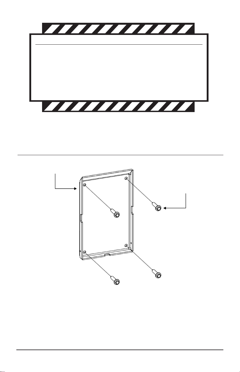
WARNING
All rigging ttings must be fully tightened and secured. Any
missing fasteners will compromise the structural integrity of the
enclosure and constitute a safety hazard. Do not suspend this
loudspeaker unless all fasteners are securely in place.
WARNING
The working load should never be exceeded. Failure to follow
this instruction may result in property damage, injury, death,
and/or legal liability to you and your company.

9
1. Secure the xed loop of the safety cable to the wall using the appropriate
user-provided bolt or hook (See Figure 8.)
2. Thread the cable through the eyebolt that is pre-installed on rear of the speaker.
3. Adjust the free cable as needed to remove slack and then secure in place using
the cable clamps that are provided.
Figure 8,
Safety Cable Installation
TOP OF
LOUDSPEAKER
EYEBOLT
SAFETY CABLE
(PROVIDED)
SECURELY ATTACH TO
MOUNTING STRUCTURE
(NOT PROVIDED)
WARNING
Cable clamps must be securely tightened. Failure to do so may
result in property damage, injury, death, and/or legal liability to
you and your company.
CABLE CLAMPS
(PROVIDED)
RIGGING INSTALLATION (cont’d):

10
Frequency Response
100
95
90
85
80
75
70
65
60
100 1000 10000
frequency (Hz)
SPL (dB)
Measured in a free-eld environment using swept one-third octave input.
Polar Measurements
-30˚
-60˚
-90˚ 90˚
60˚
30˚
0˚
125 Hz
-30˚
-60˚
-90˚ 90˚
60˚
30˚
0˚
250 Hz
-30˚
-60˚
-90˚ 90˚
60˚
30˚
0˚
500 Hz
-30˚
-60˚
-90˚ 90˚
60˚
30˚
0˚
8000 Hz
-30˚
-60˚
-90˚ 90˚
60˚
30˚
0˚
4000 Hz
-30˚
-60˚
-90˚ 90˚
60˚
30˚
0˚
2000 Hz
-30˚
-60˚
-90˚ 90˚
60˚
30˚
0˚
1000 Hz
-30˚
-60˚
-90˚ 90˚
60˚
30˚
0˚
14000 Hz
-30˚
-60˚
-90˚ 90˚
60˚
30˚
0˚
18000 Hz
-30˚
-60˚
-90˚ 90˚
60˚
30˚
0˚
10000 Hz
All polar measurements obtained in a free-eld environment at 5˚ increments. (6 dB/divisions, normalized)
Electrical Connection Wiring Guide
BLACK ......Common
BLUE ........8 Watts
GREEN ......16 Watts
YELLOW ....32 Watts
GRAY........64 Watts
BROWN .....128 Watts
RED..........8-Ohm Input
WHITE.......Connect To Red for 70V;
Disconnect for 8-Ohm

www.apogee-sound.com
11
The Apogee ALA-C1 Acoustic Line Array Loudspeaker System is warranted to be free from defects in material and workmanship
for 5 (ve) years from the date of sale to the original purchaser. Any part of the product covered by this warranty that, with normal
installation and use, becomes defective (as conrmed by Bogen upon inspection) during the applicable warranty period, will be
repaired or replaced by Bogen, at Bogen’s option, provided the product is shipped insured and prepaid to the Bogen Factory Service
Department: 4570 Shelby Air Drive, Suite 11, Memphis TN 38118, USA. Repaired or replacement product will be returned to you
freight prepaid. This warranty does not extend to any of our products that have been subjected to abuse, misuse, improper storage,
neglect, accident, improper installation or have been modied or repaired or altered in any manner whatsoever, or where the serial
number or date code has been removed or defaced.
THE FOREGOING LIMITED WARRANTY IS BOGEN’S SOLE AND EXCLUSIVE WARRANTY AND THE PURCHASER’S SOLE
AND EXCLUSIVE REMEDY. BOGEN MAKES NO OTHER WARRANTIES OF ANY KIND, EITHER EXPRESS OR IMPLIED,
AND ALL IMPLIED WARRANTIES OF MERCHANTABILITY OR FITNESS FOR A PARTICULAR PURPOSE ARE HEREBY DIS-
CLAIMED AND EXCLUDED TO THE MAXIMUM EXTENT ALLOWABLE BY LAW. Apogee’s liability arising out of the manufacture,
sale or supplying of products or their use or disposition, whether based upon warranty, contract, tort or otherwise, shall be limited
to the price of the product. IN NO EVENT SHALL BOGEN BE LIABLE FOR SPECIAL, INCIDENTAL OR CONSEQUENTIAL
DAMAGES (INCLUDING, BUT NOT LIMITED TO, LOSS OF PROFITS, LOSS OF DATA OR LOSS OF USE DAMAGES) ARISING
OUT OF THE MANUFACTURE, SALE OR SUPPLYING OF PRODUCTS, EVEN IF BOGEN HAS BEEN ADVISED OF THE POS-
SIBILITY OF SUCH DAMAGES OR LOSSES. Some States do not allow the exclusion or limitation of incidental or consequential
damages, so the above limitation or exclusion may not apply to you. This warranty gives you specic legal rights, and you may also
have other rights which vary from State to State.
Products that are out of warranty will also be repaired by the Bogen Factory Service Department. The parts and labor involved in
these repairs are warranted for 90 days when repaired by the Bogen Factory Service Department. All shipping charges in addition to
parts and labor charges will be at the owner’s expense. All returns require a Return Authorization number. For most efcient warranty
or repair service, please include a description of the failure.
11/2014-APG
Limited Warranty; Exclusion of Certain Damages
Technical Specifications
Dispersion (1M on axis):..................................140° H x 25° V
Frequency Response (1M on axis): ................150Hz - 18kHz (+/- 3 dB)
Sensitivity (1W @ 1M): .....................................93dB
Max. Power Handling (@8-Ohms):..................400W Continuous/800W Peak
Max. SPL (@1M): ..............................................118dB Continuous/121dB Peak
70V Transformer Taps: ....................................128W, 64W, 32W, 16W, 8W @ 70V
Inputs:................................................................8-conductor (stripped & tinned)
9.8’ (3-meter) long pig-tail cable included
Mounting: .........................................................Vertically adjustable (0°, 5° and 10°)
ball bracket and safety cable included
Dimensions:......................................................43” x 6” x 8.6” (110 X 15 X 22.6 cm)
Weight: ..............................................................46.8 lbs (21.23 kg)
Colors:...............................................................Black (ALA-C1B) , White (ALA-C1W)
Table of contents
Other Apogee Speakers System manuals