Apollo MAGNA User manual

awc_Apollo Compact Laminate Installation Guide
Page 1 of 12
V16 22.01.2020
APOLLO MAGNA® WORKTOPS INSTALLATION
INSTRUCTIONS
About Apollo Magna®Worktops
Apollo Magna® Worktops
Installing Apollo Magna® Worktops is easy. If, for example, you have
previously fitted a similar product then these simple to follow
instructions will enable you to successfully install Apollo Magna®.
Please read these instructions thoroughly before commencing
installation. Ensure that you read, understand and follow Health &
Safety Guidelines carefully.
Comprehensive video clips demonstrating installation and general
Care & Maintenance are available at www.sheridan-uk.com
www.sheridan-uk.com
•NSF Certified products.
•Non porous and easily maintained working surfaces
•Excellent impact resistance
•Scratches and marks can be sanded out and damage can be repaired
•Easy to install for any recognised kitchen installer or even experience DIY
specialist!
•Tested to FIRA industry standards.
•Materials backed by a 10 year manufacturer’s limited warranty – for further
details see the web site www.sheridan-uk.com.
•To View Installation Videos, visit our Youtube channel at
www.Youtube.com/Sheridanworktops. You can also view and download a digital
version of this guide from our website directly, at www.sheridan-
uk.com/downloads.
•6mm thick homogeneous solid surface bonded to an FSC E1 Grade Solid Moisture
Resistant Chipboard Core (Note - this core is dyed green to clearly identify that it is
moisture resistant grade).
•
Compreshensive range of 34mm modular worktop sizes with a range of matching
Upstands, Splashbacks, Hob Panels and Edging Strips.
•
The 6mm thick solid surface outer material wrapps around the downturned front edge
and both return edges and provides an integral wide protective Under Return to the
underside of these edges (Breakfast bars have a downturned edge on both of the long
edges and one short edge) .

awc_Apollo Compact Laminate Installation Guide
Page 2 of 12
V16 22.01.2020
ON SITE ADVICE
•Ensure that area of installation is clean and free of
dust, dirt etc.
•Use polythene sheets and dust covers to protect all
appropriate areas - a fine layer of dust will continue
to settle for at least 24 hours after the installation
is complete.
•Keep your work area clean and tidy.
•Seal the doorways of adjoining rooms with plastic
sheeting when working indoors.
•Cut the material outside wherever possible to
minimise the amount of dust inside the building.
•Use Trestles and/or a Workbenches to fully support
your workpieces.
•Ensure that the cabinets that are to support the
worksurfaces are levelled flat and are clean, smooth
Product Weight
Note that this product range is significantly heavier than most other types of laminated worktops - these 34mm Magna
worktops weigh 27.5 Kg per square metre - see the the Storage & Handling leaflet supplied in the outer packaging and the
HEALTH & SAFETY ADVICE
•Ensure adequate ventilation to enable dust and fumes
to escape when working indoors.
•Use L Class Extraction with your paower tools
•Wear FFP3Dust Masks when cutting and sanding.
•Wear Ear Defenders when cutting and sanding.
•Wear Safety Glasses when cutting and sanding.
•secure workpieces to the Trestles or Workbenches.
•Always use the correct tools for each task and ensure
that they are sharp and free from clogging and swarf.
•keep Children, Pets and visitors away from the work
area.
•Always lift or carry worktops with at least two capable
trained people out trained assistance - see the Storage
& Handling leaflet supplied in the outer packaging
Handling
•Always carry your worktops on their edge, they should be lifted and handled by at least 2 people this will prevent the
worktops from bowing and cracking under their own weight.
•Handle the worktops as little as possible, they are very heavy and the edges can be easily damaged by impacts from
their own weight.
Storage
•Prepare the storage area for your delivery, it should be a dry room at normal room temperature (18- 20°C), away
from direct heat sources and damp floors or walls.
•Store worktops flat on at least 4 equal thickness support bearers (see above)–keeping the worktop vertical on edge,
lower one edge carefully onto the bearers and then let down the other edge flat onto the bearers.
•Avoid storage in an outhouse, shed, damp garage or any room that is not weather proof, with an unstable
temperature, or in an unoccupied property.
•Avoid Storage vertically, on edge or directly on the floor, this will cause the worktops to bow and distort.
•Acclimatise the worktops to their installed room 24 –48 hours before installation –move the worktops into or next to
the installation site and unpack, store flat on the floor as before but with dividing bearers between each worktop to
allow good air circulation.
•Avoid Installing in any room that is freshly plastered, with any residual damp or that is unheated.
•Avoid Installing in any newly built unoccupied property unless it is properly heated and ventilated.
Apollo® Magna Worktop
4 Dividing wooden strips
4 Wooden Bearers
agna
Apollo® Magna Worktop
Health & Safety
Handling & Storage
Apollo Magna® Product Specification
•Available in a variety of styles and sizes:
•6mm thick solid surface bonded to an FSC
E1 Grade Solid Moisture Resistant
Chipboard Core providing integrated
resistance to moisture ingress.
•Easily Trimmed to size and can be re-
finished to suit.
•Easily Installed with inconspicuous joints for
a seamless appearance
•Curved End Corner, Sink and Drainer
Groove Jigs available.
•6mm Solid
Surface
•FSC E1 Grade
Solid Moisture
Resistant
Chipboard Core
providing
integrated
resistance to
moisture ingress.
•Wrap around
construction.

awc_Apollo Compact Laminate Installation Guide
Page 3 of 12
V16 22.01.2020
Planning and Designing your Worktop Layout
Maximum Overhang for all
worktops is 300mm,
depending on the
installation position and
use extra support may be
needed using suitable wall
battens or brackets.
Joints must be a
minimum of 100mm
from Sink or Hob
Cut Outs
Min.
50mm
from the
edge.
Min.
50mm
from the
edge.
Joints above Appliances are
acceptable providing front and
back support rails are fitted.
Joint
_ _ _ _ _ _ _ _
Min 100mm
Joint
Min 100mm from
Joint
--------------------
Diagonal
corner, use a
standard
worktop up to
600mm deep
Mitred Joints are not
permitted in any
position except for
Veined colours, see
pages 3 & 4.
Always use this type
of corner solution,
across the worktop
and square to it’s
Maximum
unsupported
Overhang 300mm
Where possible, for correct support, plan all joints
to be situated directly above floor cabinet ends
Joint above the Floor Cabinet ends.
Try to avoid planning two appliances together. If
unavoidable, fit an intermediate end panel
Corner Joints should never be mitred.
Dish
Washer
Sink
Careful planning is the key to successful installation. If possible begin planning with a pre-site survey.
When designing your Worktop Layout, you should start by establishing where the Sink and other appliances will be
installed and then the corner from where you will start to install each of the worktops, from this you can plan where the
Fig. 1 Apollo Magna Worktop
Layout considerations
When planning your worktop layout:
•Ensure joints do not fall on or within 100mm of
cutouts.
•Plan how you are going to fit each top and the
resulting joints, avoid both joints in the same
direction in a “U” shaped layout.
•Ensure cutouts are at least 50mm from worktop
edge
•Joints in worktops should fall on a carcass end not
in the middle, this gives added support to a joint
•Each worktop requires an expansion clearance (to
the wall) of 1mm for every linear metre of
worksurface (i.e. 3mm for a 3 metre length)
•Magna® worktops should not be planned to have
overhangs greater than 300mm.
•Allow at least 120mm between heated Cut Outs.
•Allow at least 50mm behind an electric hob or
100mm behind a gas hob to the front of any
Splashback that is over 100mm in height.
•All worktops over gaps between floor cabinets (i.e.
for appliances) greater than 600mm long, must be
supported with suitable wall battens to add support
and stop bending under load
•All worktops over spaces unsupported by the floor
cabinets greater than 600mm long (i.e. some Sink
and Corner Cabinet designs) must have additional
support along the walls using suitable wall battens
•Where fitting over two adjacent appliances is
unavoidable, always fit an End Support Panel
between the two appliances –see Fig 2.
•Corner joints should never be mitered into the
corner.
Magna® Worktop Joints
•Always use Masons Mitre (also called Butt & Scribe)
jointed corners –see the full details on Page 9.
•The Loose Tongues required for these joints are
supplied with the 3Mx600mm Worktops–enough for
2 joints inside the packaging -.Note, these are not
Edging Strips.

awc_Apollo Compact Laminate Installation Guide
Page 4 of 12
V16 22.01.2020
Tools and Materials Required
Cutting to Size
Before Installation
•Unpack immediately before fitting and check all components for damage and colour match before commencing
installation. This can be easily done by butting the components together and wiping the adjacent areas with a damp
cloth. Whilst damp, this will show the colour after final finishing of the separate components.
•These Worktops are manufactured to strict tolerances but some variation in colour will occur with this type of material.
Should there be an unacceptable colour variance, please contact your store before commencing installation. Claims for
damage or colour variation cannot be made after installation.
•Level all Floor Cabinets and End Panels front to back, along the length and around corners before any measuring or
installation.
•Check the site conditions and where required, fit support battens to the walls along all gaps between floor cabinets,
unsupported lengths greater than 600mm (i.e. behind Corner and Double Floor cabinets) and along the walls in spaces
for appliances between floor cabinets.
•Ensure that you have the correct Colour Coordinated Glue for all joints and edging –supplied separately in 100ml Glue
Cartridges, sufficient for 2 full worktop joints or 12 metres of Upstand. If in doubt, check with your store.
•Ensure that you have sufficient sheets of Moisture and Heat Resistant aluminium membrane (supplied in the
Installation Kit) to be fitted to the worktop underside above any appliance (i.e. Dishwasher or Washing Machine) or
moisture and/or heat emitting objects (i.e. radiators). Claims cannot be made for swollen, cracked or distorted worktops
above appliances that have not had this membrane fitted.
•Ensure that you have sufficient Moisture and Heat Resistant Aluminium Tape (supplied in the Installation Kit) to be
fitted according to the instructions to the edges of worktop cut-outs for Hobs and other heat generation appliances.
Claims cannot be made for swollen, cracked or distorted worktops around appliance cut-outs that have not had this tape
fitted.
•N.B. This Tape must bridge the joint line between the bottom edge of the Downturn (front edge) and the bottom face of
the white coated Chipboard core material.
GENERAL TOOLS –not supplied by Sheridan
Fabrications
•Random orbital sander plus dust extraction equipment.
•Hand router: minimum of 1850W with ½”/12.7mm Colet size.
•30mm Guide Bush
•12.7mm x 40mm TCT Router Cutter.
•Straight Trimming Router Cutter (with a guide bearing).
•Drainer groove cutter –if required to make drainer grooves.
•Wide Chisel (minimum 1”/25mm)
•Electric saw –with fine tooth blades.
•Power planer.
•Silicon Gun.
•Hot Melt Gun.
•“G” Clamps.
•Softwood Blocks
•Biscuit Joint Router Cutter
Various Jigs are available to help install Sink & Hob
Cutouts and Drainer Grooves to suit your installation
SOLID SURFACE® INSTALLATION KIT - CONTENTS*
•Sandpaper 100, 150, 220grit
•Abrasive Pads
•Self Adhesive Aluminium Heat and Moisture membrane
Foil
•Heat Reflective Tape
•Fixing Pack of Screws, Washers & Brackets
Not supplied by Sheridan Fabrications
•Silicone Sealant (High Modulus) for sealing edges to walls
and cabinets.
•Rotobond 2000 MS Polymer Sealant - recommended for
fitting all under mounted sinks.
Mask off the section of worktop to be cut and mark the
cutline on the masking tape.
Cut the blank to size squaring ends using router fitted
with sharp, double-fluted tungsten carbide straight
cutter and a straight edge (Fig. 3).
When routing through the thickness of the
worktop, to ensure a clean cut and avoid “chatter
marks”, make 3 to 5 passes along the cut
increasing the depth of cut by 6/7mm with each
pass until the complete thickness is cut through.
For instance this will take 5-6 passes for 34mm
thick Magna worktops.
Curved corners can be achieved using the router as
Fig. 3: Cutting to size using a Router

awc_Apollo Compact Laminate Installation Guide
Page 5 of 12
V16 22.01.2020
Fitting End Edging Strips - Straight and Curved
Fitting a Straight Edging Strip: –see Fig. 4
These Apollo Magna® Worktops have finished downturns on both ends of
the worktops and when cut to size they can usually be fitted with any cut
end being concealed against a wall. However when this is not possible a
6mm thick solid surface Edging Strip is available to finish the cut to size
end of a worktop.
The Edging Strip is designed to be fitted onto the chipboard core of the
worktop underneath the 6mm thick top surface, this preserves a seamless
top surface and enables the fitted edge to have an unobtrusive joint.
Prepare the worktop by first cutting to the required overall length plus a
trimming allowance of 2mm. Now turn the worktop upside down. Using a
hand router, cut back the chipboard of the cut end by 8mm leaving space
for the Edging Strip and a 2mm overhang. Do not remove the front
downturn or the top Solid Surface. Then increase the depth of the cut to
remove 0.5mm of the underside of the top surface leaving 5.5mm
thickness, this will enable the Edging Strip to bond to the top surface.
With a chisel, remove the chipboard “fillet” (left by the router cutter) behind
the front downturn to allow space for the edging strip to fit right up the back
face of the front downturn –see top right of Fig. 5.
Clean the face and edges of the Edging Strip to be used with the alcohol
wipes supplied, clean the prepared cut back faces of the worktop end in
the same way, allow to dry. Keep the work area dust free to avoid
contamination of the glue joint.
Using the correct coloured Magna® Glue Cartridge, apply continuous
beads of glue to the chipboard core and the inner faces of the solid
surface top and front downturn. Without touching the face and edges to be
glued, position the Edging Strip and squeeze into place ensuring that a
continuous bead of glue flows out of the joint line and that the edging strip
is pressed up to the back face of the front downturn.
Clamp in position and allow the glue to cure to a hard consistency, this
usually takes 30 to 40 minutes dependent upon the ambient temperature.
Using a hand router fitted with a straight trimming cutter (fitted with a guide
bearing, see Fig. 5a.); remove the 2mm overhung edges of the solid
surface material.
If required to match the factory finish on the front edges of the worktop,
this can be completed where required using a profile cutter (with bearing)
having a 3mm radius.
When all trimming and profiling is finalised, sanding and finishing can be
completed following the instructions later in this guide in the section
“.Finishing the Joints”.
Fig. 5: Straight Timming Router cutter with
guide bearing
Fig.6: Positioning the Router Jig to remove the
FSC Chipboard core, working from the
underside of the Magna Worktop.
Fitting Curved Edging Strip: see Figs 6, 7 & 8
The ends of these Apollo Magna® Worktops can also be shaped into
curves to suit Curved Floor Cabinets. For this purpose, a preformed 6mm
solid surface Curved Edging Strip is available to finish the cut to size and
shaped end of a worktop, a Router Jig is also available specifically to
enable the installer to produce a worktop with a shaped curved end to fit
the Curved Edging Strip.
As for the straight Edging Strip above, the Curved Edging Strip is designed
to be fitted onto the chipboard core of the worktop underneath the 6mm
thick top surface, it is fitted in much the same way and this preserves a
seamless top surface and enables the fitted edge to have an unobtrusive
joint.
Prepare the worktop by first cutting to the required overall length plus a
trimming allowance of 2mm then turn the worktop upside down.
The Curved End Jig is designed for use with a suitable hand router (ideally
for 12.7mm/ ½” Collets) used with a 12.7mm (½”) straight router cutter and
a 30mm guide bush. The Jig has 2 curved profiles to be used on the
Bottom and Top faces of the worktop, it can be flipped over to use for Left
or Right Hand curved ends, it is engraved to help identify which way up to
use and how to position correctly. Start with the Bottom Face part of the jig.
Place the jig on the underside with the “Bottom Front Edge” flush with the
front edge of the Top and the “Side” set back 17mm from the edge of the
return end, and clamp in position.
Fig. 4: Fitting the Edging Strip

awc_Apollo Compact Laminate Installation Guide
Page 6 of 12
V16 22.01.2020
Fig. 8: Fitting the Curved Edging Strip
The method is to start at the step in the front edge of the jig and follow the
full curve and along to the back edge of the worktop, removing the
chipboard core
into a curved shape set back from the front edge sufficiently to fit the 6mm
thick curved edging strip.
Do not remove the excess Top Solid Surface at this stage, see below.
Then increase the depth of the cut to remove 0.5mm of the underside of
the top Solid Surface leaving 5.5mm thickness, this will enable the Curved
Edging Strip to bond to the top surface.
With a chisel, remove the chipboard “fillet” (left by the router cutter) in the
start of the cut behind the front downturn to allow space for the edging
strip to fit right up the edge of the front downturn and flush with it’s front
face.
Next, turn the worktop over to work from the top face. Position the jig on
the top face with the side edge set 15mm back from the return end and
the leading front edge aligned with the worktop front edge.
Set the router plunge depth to cut through the top Solid Surface material.
Again, the method is to start at the step in the front edge of the jig and
follow the full curve and along to the back edge of the worktop removing
the excess top material leaving space underneath against the chipboard
core for the Edging Strip and a 2mm overhang along the side return end
edge tapering to no overhang on the front edge.
The Curved Edging strip is supplied with extra length on the front and side
edges to help it to be fitted exactly. The extra length on the front needs to
be trimmed off to fit neatly into the rebate that you have created in the
Front Downturn. The extra length on the side edge is trimmed off after
gluing in place.
Clean the face and edges of the Edging Strip to be used with the alcohol
wipes supplied, clean the prepared cut back faces of the worktop end in
the same way, allow to dry. Keep the work area dust free to avoid
contamination of the glue lines.
Using the correct colour matched Magna® Glue Cartridge, apply
continuous beads of glue to the chipboard core and the inner faces of the
solid surface top and front downturn. Without touching the face and edges
to be glued, position the Edging Strip and squeeze into place ensuring that
a continuous bead of glue flows out of the joint line and that the front end
of the edging strip is pressed up to the inner face of the cutout in the front
downturn –see the 2 middle views of fig. 7 to the right .
Clamp in position and allow the glue to cure to a hard consistency, this
usually takes 30 to 40 minutes dependent upon the ambient temperature.
Using a hand router fitted with a straight trimming cutter (fitted with a guide
bearing); remove the 2mm overhung edges of the solid surface material.
If required to match the factory finish on the front edges of the worktop,
this can be completed where required using a profile cutter (with bearing)
having a 3mm radius.
When all trimming and profiling is finalised, sanding and finishing can be
completed following the instructions later in this guide in the section
“Finishing the Joints”.
NOTE: This method of fitting both Straight and Curved Edging Strips
is the only one supported by the 10 Year Manufacturers Limited
Warranty; the use of any other method will invalidate this Warranty.
6mm
6mm
Fig. 7: Positioning the Router Jig to
remove the excess Solid Surface,
working from the Top Face of the Magna
Worktop.

awc_Apollo Compact Laminate Installation Guide
Page 7 of 12
V16 22.01.2020
Scribing the Worktop to the Wall (where necessary)
The scribing process reflects the contours of uneven back walls
to the worktop, allowing the correct overhang at the front of the
base cabinets. It may not be necessary to scribe worktops to the
Line of the Corner
where Walls 1 and
2 meet Wooden Block
Spacer
• To scribe this edge, offer the panel to the wall in it’s planned
position on the supporting cabinets touching the wall in at least 1
place, line up the front edge parallel with the cabinets - the front
overhang should be 30-35mm. If the overhang exceeds this it
may be necessary to trim material from the back edge of the
worktop to allow it to fit correctly, if the wall is uneven and the
back edge needs to be scribed then follow these instructions.
•You need to use a wooden block as a spacer (or a disk with a
central hole for a pencil) to mark the edge of the panel parallel to
the wall and therefore If any of the panel needs to be trimmed off
to fit against the wall with minimal gaps–measure the width of the
spacer from it’s outer edge to the centre of your pencil (or the
distance from the edge of the Disk to the pencil hole) –this is the
spacer width - See image right.
•Apply masking tape along the back edge
Move the panel away from the corner such that the widest gap is
6. Sealing the Scribed Edges
When Scribing is complete, it is advisable to seal the exposed chipboard core against moisture ingress from the
surroundings using PVA Adhesive. When fitted, the joint between all worktops and any walls should be sealed with a bead
of flexible silicon sealant.
7. Hot Pipes
When hot pipes need to pass through the worktop, there should be a minimum clearance of 10mm between the cut-out and
the pipe(s) in order to stop heat transfer from the pipes to the worktop and to comply with the warranty. In most cases the
pipes will be boxed in concealing the clearance hole and stopping any damage to the worktop from spilled liquids. Even with
boxing in place the edges of the cut-out must be sealed well with PVA Adhesive to stop any possible water ingress.
This line will now match the shape of the wall –this is
your scribing line - See image above.
•Machine off all of the material on the outside of the
scribing line using a jig saw for rough cuts but finishing
Hob & Inset Sink Cut Outs
Remove excess heat reflective tape with a knife
Fig. 9 Hob/Sink template clamped in position
Fig. 10 Application of Heat Reflective Tape
•Follow the instructions and the template supplied with the Hob or Sink or use them
to make a Jig from the Template that will enable you to make the Cut Out in the
Magna® Solid Surface and the rebated Cut Out into it’s underside.
•Clamp the hob or sink jig/template in correct position onto the worktop (Fig. 8).
Check that corners have correct radius for the hob or sink (some sink radii are
rather large) before commencing. In all cases use a minimum cutter diameter of
12mm and ensure that the minimum radius of 6mm is left inside each corner - do
not remove it to leave a square corner.
•All cut-outs must be machined using a router with a 12.7mm router cutter and a
30mm guide bush. When routing through the thickness of the worktop, to ensure a
clean cut and avoid “chatter marks”, make 3 to 5 passes along the cut increasing
the depth of cut by 6/7mm with each pass until the complete thickness is cut
through.
•Remove the sharp top and bottom edges with fine sandpaper or profile the edges
with a 2mm radius all round using a router.
•The edges of the exposed chipboard core of all cut-outs must be sealed well with
PVA Adhesive to stop any possible water ingress.
Hob Cut Out only: see Fig. 9 & 10
Please Note: The inner edge of the Cut Out must leave 6mm clearance around all
sides of the hob to stop excess heat transferring into the worktop.
Apply heat reflection tape around the entire cut out (Fig. 10), ensuring that it
protrudes beyond the hob flange and is in contact with worksurface and hangs
straight down, heat reflection tape is required for all hot cut outs. Apply a second
piece of reflective tape to all corners to ensure adequate coverage.
Fitting Inset (Top Mounted) Sinks and Hobs:
•Before installing Hobs or Inset Sinks, ensure that the top face of the worktop around the cut out is thoroughly clean and dust free then
degrease using the alcohol wipes (provided in the Installation kit) and allow to dry.
•Always follow the installation instructions supplied with the Sink or Hob including sealing between the Sink or Hob and the work surface.
•If there are no instructions to seal between the Sink or Hob and the Work Surface, this must be completed as follows: - Apply a
continuous bead of Rotobond 2000 or suitable High Modulus Silicon sealant to the flange of the sink and press into position, ensure that
the bead is squeezed out continuously all along the joint line to provide a watertight seal. Following the sink instructions tighten all of the
sink clamps.

awc_Apollo Compact Laminate Installation Guide
Page 8 of 12
V16 22.01.2020
Under Mount Sinks & Drainer Grooves
Undermount Sink Cut Out
•Follow the instructions and the template supplied with the Hob or Sink or use them to make a Jig from the Template that will enable you
to make the Cut Out in the Magna® Solid Surface and the rebated Cut Out into it’s underside.
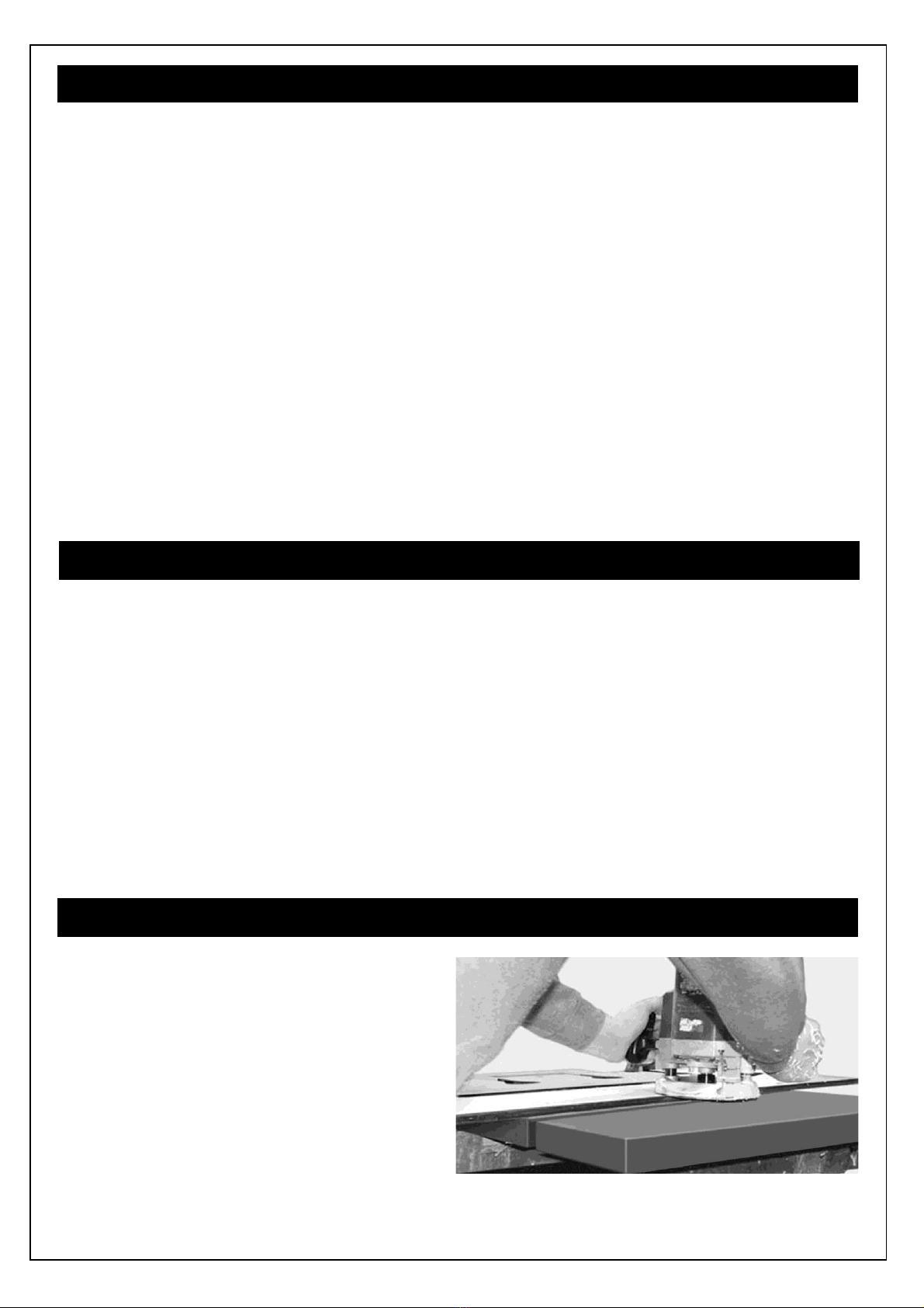
•. Clamp the hob or sink jig/template in correct position onto the worktop (Fig. 8). Check that corners have correct radius for the hob or
sink (some sink radii are rather large) before commencing. In all cases use a minimum radius of 6mm.
•All cut-outs must be machined using a router with a 12.7mm router cutter and a 30mm guide bush. When routing through the thickness
of the worktop, to ensure a clean cut and avoid “chatter marks”, make 3 to 5 passes along the cut increasing the depth of cut by 6/7mm
with each pass until the complete thickness is cut through.
•Remove the sharp top and bottom edges with fine sandpaper or profile the edges with a 2mm radius all round using a router.
Fitting Under mounted Sinks to a Cut Out:
Please Note: If Drainer Grooves are required, they should be made at this stage, please refer to the later section “Installing Drainer
Grooves” before continuing.
Using the instructions above, cut the opening in the top surface for the under mounted Sink using the Template supplied with the sink.
The underside of the sink cut out is made next, ensuring that the worktop is fully supported and that the working surface is dust and
debris free, turn it over to be face down to work on the underside.
•As before, accurately clamp the correct jig into position onto the underside of the worktop ensuring that the jig handing corresponds to
the Cut-out handing.
•Using a hand router carefully remove the excess chipboard from the back face in 2or 3 passes, the final pass should remove 0.5mm of
the underside of the solid surface material, leaving 5.5mm thickness of solid surface material around the sink Cut-out material to provide
a fresh clean and flat face to fit the sink flange into, this is needed for the silicon sealant to fully seal the sink to the worktop
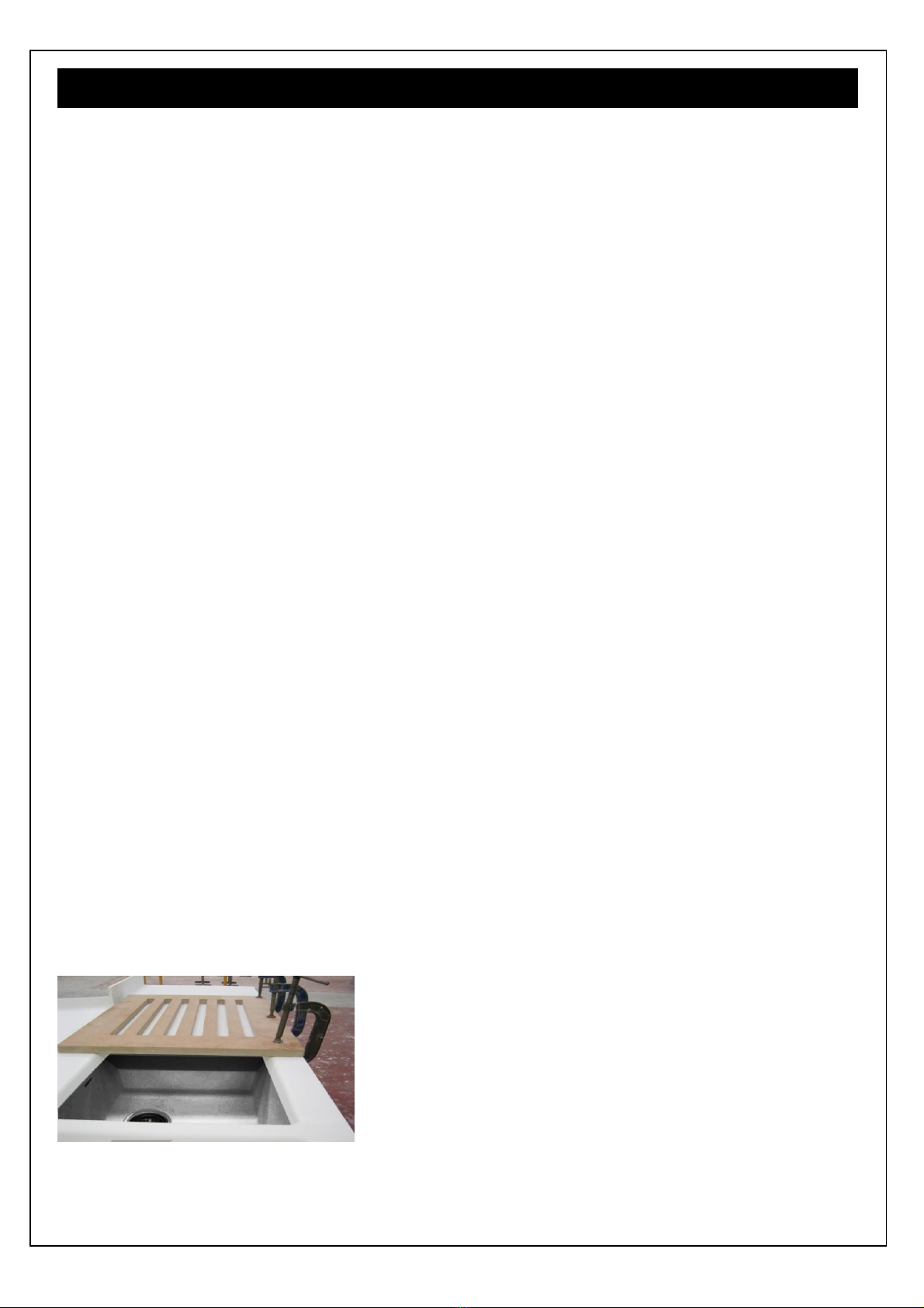
•Confirm that the fit is correct by placing the inverted sink (s) in position without any sealant; adjust the machined “rebated” edges to suit.
•The edges of the exposed chipboard core of all cut-outs must be sealed well with PVA Adhesive to stop any possible water ingress.
•Before installing under mounted Sinks, ensure that the underside of the exposed solid surface face of the worktop around the cut out is
thoroughly clean and dust free then degrease using the alcohol wipes (provided in the Installation kit) and allow to dry.
•Apply a continuous bead of Rotobond 2000 or suitable High Modulus Silicon sealant to the flange of the sink and press into position,
ensure that the bead is squeezed out continuously all along the joint line along both the inner and outer edge to provide a watertight
seal. Following the sink instructions, fit (using 12mm screws) and tighten the sink clamps in the correct order and then remove excess
sealant and smooth the bead then leave without moving to allow the sealant to set.
•Apply a length of the Aluminium Reflective Tape along this front edge and in any position that is exposed to moisture (i.e. in front of a
dishwasher), This Tape must bridge the joint line between the bottom edge of the Downturn (front edge) and the bottom face of the white
coated Chipboard core material.
•Note: If a Wasted disposer is to be fitted to an Under mount Sink, the sink will need additional independent support such that the weight
of the Waste Disposer is not supported by the Under mount Sink. Additional extra support is also required such that the weight is not
supported by the worktop if a Ceramic Sink is fitted.
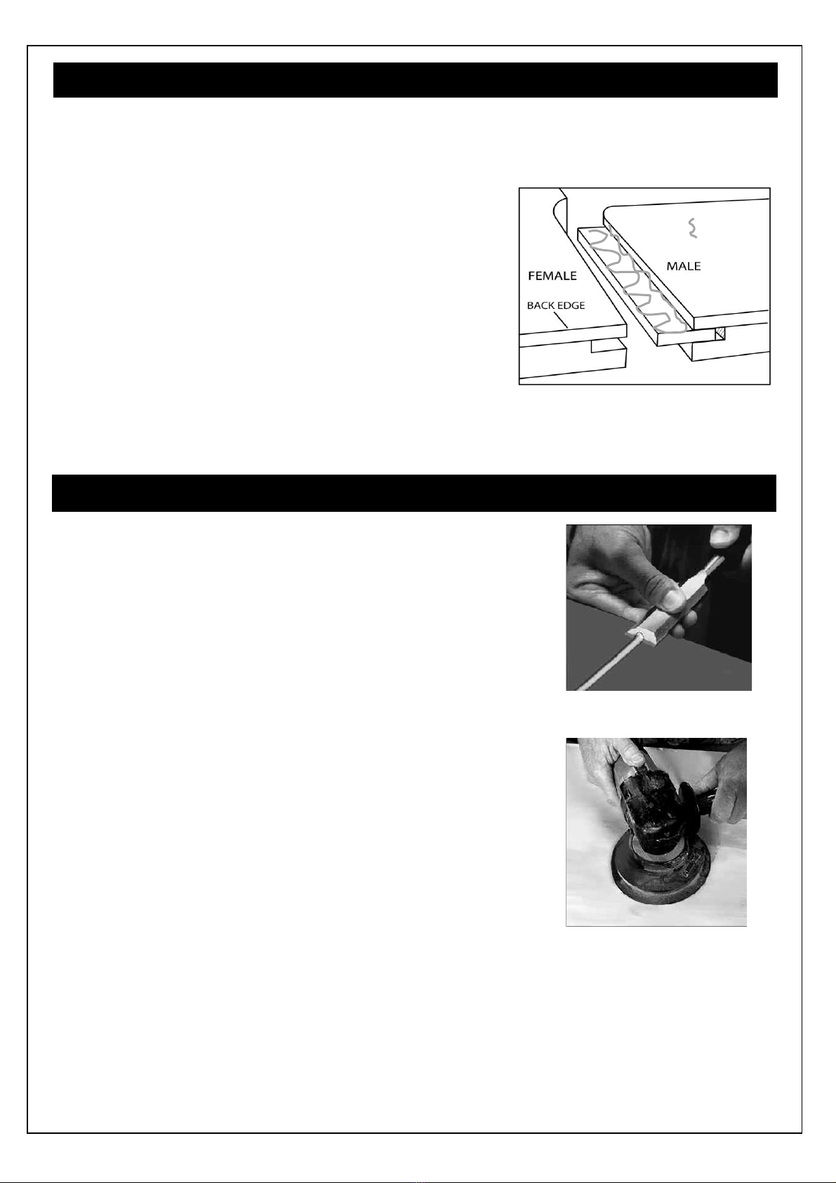
Hand Sanding the Drainer Grooves.
•Using the sandpaper pads supplied (wrapped in a loop around a spare
Hot Melt Glue cartridge) in the correct order of 100 grit, 150 grit and finally
220grit, sand along the grooves.
•Complete the finishing process using the supplied abrasive pads in the
correct order of Maroon, Grey and finally the white Abrasive Pad.
•The white abrasive pad should be used on a dust free surface that has
been wetted with the Stone guard cleaner spray.
Installing Drainer Grooves:
•A Jig is available for the cutting of Drainer Grooves. The jig is designed for up to 6 grooves but you can install the quantity required to
suit your sink , either using part of the jig for fewer grooves or using it in another position to add more grooves.
•Place the Jig in the position that suits your needs –it is 600mm deep (the same depth as your worktop) –if you line up the front and
back edges the grooves will be positioned central to the worktop. You can also vary the length of the grooves to extend them further
from the sink bowl by moving the Jig either closer or further away from the sink along the worktop.
•Clamp the Jig firmly in the desired position.
•Use a hand router fitted with a 30mm guide bush and a 25mm diameter “Water Channel” cutter, set the plunge depth to 2mm – do not
cut deeper than 2mm.
•Starting at the end away from the sink, plunge the router and machine smoothly along the Jig to create the drainer groove –do not
force the router and try to finish in one pass along each groove –this will provide a smooth finish that is much easier to sand and finish.
•Check the Jig position and clamps and repeat for all of the remaining grooves that you require.
•Follow the finishing instructions to hand sand and finish the grooves as described below.
Tap Holes
•Tap holes are drilled with a hole saw fitted with an appropriate sized cutter with fine teeth, then remove the sharp top and bottom and
hole edges with fine sand paper. The edges of the exposed chipboard core of the tap hole must be sealed well with PVA Adhesive to stop
any possible water ingress.

awc_Apollo Compact Laminate Installation Guide
Page 9 of 12
V16 22.01.2020
Preparingthe Joint
Fig.12: Masons Mitre Jig
shown on Left and joint
faces shown below
Joint Type
Apollo Magna® Worktops should only be joined by means of a
Masons Mitre Joint (also called a Scribed Butt Joint) supported by
a Loose Tongue (also called a Cleat) inserted into a groove in the
two faces of the joint.
Male and Female Masons Mitres - see Figs. 12 and 13.
A Masons Mitre Joint is made up of Male profile in one worktop and
a Female profile in the other worktop to be joined to it, the male
and female profiles are joined together using a Loose Tongue
inserted into a groove in both faces of the joint.
Using the specified coloured adhesive an unobtrusive and visually
seamless joint can easily be achieved with basic laminate worktop
jointing experience.
Male and Female Masons Mitres –see Fig. 12
With a standard worktop jig, prepare male and female masons
mitres on the required mating surfaces of the 2 worktops to be
jointed, using a router fitted with a standard straight Tungsten
Carbide cutter and guide bush as specified for the jig being used.
It is recommended that the Chipboard Core surfaces of all joints
are lightly hand sanded using a Sanding Block to remove any loose
or proud chipboard Particles before sealing well against water
ingress with PVA Adhesive –allow to dry before the next stage,
but wipe off any PVA from the solid surface edges with a damp
cloth.
Fig.15: Timber blocks and G-clamps
Loose Tongue –see Fig 13
Using a 6mm groove cutter or a 4mm Biscuit cutter (2 passes), router a
6mm wide 14-16mm deep groove into each face of the male and female
joint, cut this groove immediately below the bottom edge of the of the
solid surface top material where it is bonded to the chipboard core.
This groove should be along almost the whole length of the joint, finishing
just short of the back face of the front edge solid surface material –
roughly 8mm from the front face.
Each joint requires a Loose Tongue to fill the length of the joint; these are
made from 6mm solid surface and are supplied in the 3M x 600mm
Apollo® Magna Worktops
Fig.14: Clean the joint
Worktop Joint: see Figs. 14 & 15
The key to making a good seamless joint is to ensure that both sides of the joint
are perfectly mirror matched. Assemble the joint dry (without adhesive) and
check that the seams are parallel, with no gaps showing, and that the two
surfaces are not stepped when brought together (redress to square edge with
hand router if necessary).
Apply timber blocks to either side of
the seam using hot melt glue, and
use G-clamps to bring them together
(n.b. Do not use hot melt glue on the
end grain of the timber blocks as
this makes the blocks difficult to
remove). Alternatively, suction cups
can be used to bring the joint together.
If it is unavoidable that a joint falls over a void or over the centre of a floor
cabinet, you must provide extra support under the joint line, i.e. an additional
batten fitted into the floor cabinet between the front and back rail.
Before bonding the joints, it is important to ensure that the seam is free from
any contamination. Immediately before applying and glue, both faces of the joint
that have been skimmed and checked as above must be cleaned with an
alcohol wipe (included in the Installation Kit) and allowed to dry. Do not touch
the cleaned areas except with glue.
Fig.13: plan view of the prepared joint
showing the Loose Tongue
The range of Apollo Magna® Worktops are supplied with a colour coordinated Glue for bonding joints and edging strips. The Glue
is supplied in 100ml Glue Cartridges that are designed to be used with a standard glue gun, each cartridge is sufficient for2 full
worktop joints and is supplied with 3 mixing nozzles –if there is more than 20 minutes between each use change to a new nozzle.
Important: Ensure that the glue cartridge fits flush against front of the glue gun and that the glue gun adapter (a large black
plunger supplied in the glue Kit) fits squarely in the glue cartridge. Fit the mixing nozzle.To ensure correct mixing and
hardening discard the first small amount of extruded adhesive folling the instructions on the plastic bag outer
packaging.

awc_Apollo Compact Laminate Installation Guide
Page 10 of 12
V16 22.01.2020
Gluing the Joints
Ensure that the work area is clean and dust free to avoid
contamination of the glue which could lead to a visible joint line.
Place the worktops as close to their final installed position as possible
to avoid unnecessary handling after the joint is bonded together.
See fig. 16
Apply Apollo® Magna Glue to the top surfaces of the Loose Tongue,
to the faces of the joint edge and to the inner edges of the front face
material. Insert the loose tongues into the groove in one face of the
joint.
Push the two parts of the jointed worktops together leaving a small
gap (2mm wide). Apply masking tape to the underside of the front
edge of the worktop joint line to prevent the glue from dripping out
onto the floor cabinets.
Apply a continuous bead of Glue to fill the gap into the joint line
ensuring that sufficient Glue is used so that a continuous bead of Glue
flows out of the joint line when the joint is clamped closed.
Apply pressure to close the joint with the G Clamps or Suction Cups,
check for correct alignment and the top faces are flush and adjust
before applying final pressure, check that a continuous bead of Glue
has squeezed out of the joint line.
The Glue will cure to a hard consistency; this usually takes 30 to 40
minutes dependent upon the ambient temperature.
Fig. 16 Magna®Joint: Loose Tongue
positioned in the joint and glue applied.
APPLIEDG
LUE
Finishing the Seam (Joint Line): see Fig. 17
After the Glue has cured, remove the G clamps then, using a wide sharp
chisel, remove the glue blocks and then the hot melt glue deposits –take
care to keep the chisel flat to the top face to avoid digging into the
surface.
The Sanding Process: See Fig. 18
Generally the use of a Random Orbital Sander will cut faster and more
efficiently with a finer finish than other methods, the use of Random
Orbital Sander is therefore recommended. Care must be taken to avoid
gouging the surface during this process.
Ensure that the sander is kept continually moving to prevent localised
dips in the surface due to over sanding.
Use the sandpaper pads supplied in the Installation Kit in the correct
order of 100grit, 150grit and finally of 220 or 240 grit in order to achieve
the same results as the factory finish, blending approximately 600mm
beyond the Seam Area to avoid patchiness. Take care to avoid the
sandpaper becoming clogged with sanded material, this can lead to
localised scratches will that require more work to remove before final
finishing.
Complete the finishing process using the supplied abrasive pads in the
correct order of Maroon Abrasive Pad, Grey Abrasive Pad and finally the
white Abrasive Pad, the White Abrasive Pad should be on a dust free
surface that has been wetted with the Stone guard Cleaner Spray.
Note, Black and Dark finishes:
These colours are more likely than light colours to show slight differences
in surface finish when first installed. To avoid this it may be necessary to
apply the final finish process (described above) to the whole worktop
installation rather than just around the joints. Fig. 18 Sanding using random
Fig. 17 Removing glue deposits
Finishing the Joints
These colours are more likely than light colours to show scratches and marks in high traffic areas (i.e. around hobs, sinks and
the kettle), for this reason they require a more regular maintenance regime to retain the finish and to avoid patchiness.
Note:
If a slightly matt surface is desired, the final finishing should be completed using the Grey Abrasive Pad and Stone Guard
cleaning spray, however this is not recommended for black and dark finishes because the full depth of colour will not be
achieved using this method.

awc_Apollo Compact Laminate Installation Guide
Page 11 of 12
V16 22.01.2020
Fixing the Worktops to the Floor Cabinets
Magna® Worktops: When the jointed and finished worktops are in the final position, they should be fixed in place using
the Screws, Washers and Expansion Brackets provided in the Installation Kit.
Always use the supplied washers to screw through the slotted holes in the brackets into the worktop underside, this
allows the worktops to naturally expand and contract; washers are not needed to screw the brackets into the floor cabinet
sides.
Fix the worktops to the floor cabinets at least every 600mm at the front and back of the cabinets.
The screws supplied or recommended are the correct size for this, they should only screw into the chipboard core and
not screw into the 6mm Magna Solid Surface material; using the washers as described is very important because it allows
the natural expansion and contraction movement of the worktop to occur without affecting the secure fixing.
If it is necessary or more convenient to fix the tops in place by screwing through the floor cabinet Front and/or Back Rails,
longer screws are required (1” or 25mm No.6 Round Head Chipboard Screws- not supplied). Drill 6mm Diameter
clearance holes through the Front and Rear Rails of the cabinets, always using the supplied washers, screw through the
washer and the holes in the Rails into the chipboard core of the Magna worktops and directly into the Slab Tech worktop
underside using pilot holes as above.
Notes:
Use this space to attach all Product Labels and delivery details after the products are
unpacked

awc_Apollo Compact Laminate Installation Guide
Page 12 of 12
V16 22.01.2020
Care & Maintenance
Care & Maintenance
Important: Please read the information carefully and ensure
your keep these instructions for future reference.
Always refer to the Care & Maintenance video on
www.sheridan-uk.com.
Replacement Care & Maintenance products are available through
www.sheridan-uk.com/apollo-care-kits.
Looking after your Apollo Magna® Worktops
Apollo® Magna worksurfaces not only look very attractive and
exude quality; they are designed to withstand the rigours of
everyday use.
Upon installation an Apollo® Magna worksurface will have an
overall satin sheen finish. However, through use, the worksurface
acquires a smoother, more silken finish and appearance. Even the
cleaning properties appear to improve with use. Unlike most other
worksurfaces Apollo® Magna is ‘repairable’, so little accidents,
stains or scratches can usually be removed with relative ease.
Your Installation & Maintenance Kit contains all of the items
required to help keep your new worksurface in pristine condition.
Stone Guard is an anti-bactericidal surface cleaner specially
formulated to tackle grease and grime leaving surfaces sparkling
clean with a residual antibacterial effect.
Cream Cleaner is a renovating cream cleaner that will remove
minor scratches and more stubborn stains from solid surface
worktops.
Important: Please read and follow instructions carefully when
using care & maintenance products. Always wear rubber gloves
when using chemicals to prevent any cracking, drying or other
reaction to your skin.
Every day cleaning
Remember, it is always easier to wipe up a spill than to have to
deal with a dried-on stain.
Apollo® Magna worksurfaces are impervious to liquids however it
is always best to clean up spills as they occur.
Wipe the worksurface, with a damp cloth and the Stone Guard
cleaner, (supplied in the Maintenance Kit), to remove any oils and
fat. Buff dry with a soft white cloth (also in Kit).
If any stains need further attention, allow the Stone Guard 30
seconds contact time, before wiping and rinsing. If required apply
the Cream Cleaner with a damp cloth then the stone guard as
above.
If your worksurface has an integrated sink, clean this in the same
way as the worksurface.
Once a week after cleaning, fill the sink with warm, (not boiling),
water; add 1-2 teaspoons (5-10ml), of liquid household bleach and
leave to soak for a few hours, or overnight. This will help to
maintain a beautiful white clean finish.
●Hard water will always leave water marks on non porous
surfaces, these can easily avoided by wiping up and drying any
splashes immediately. Dried on water marks and light limescale
build up can be removed using a solution of 50% white vinegar
and clean water left in contact with the marks for no more than a
minute before rinsing with clean water and buffing dry. Regular
maintenance can use a solution of 10 % white vinegar and 90 %
water to dampen a clean cloth to wipe over and then rinsing and
drying as before
Persistent stains
To remove more persistent stains from the worksurface or
integrated sink use the Abrasive Pads (White, Grey & Maroon),
provided in the Kit.
Always use the least abrasive pad possible to remove marks.
Always rub in a circular motion.
Start with the White Pad, rubbing the stain in a circular motion. If
To remove any abrasion marks and to restore the
worksurfaces former luster polish, use progressively less
abrasive pads. Always finish by using the White Pad in
conjunction with the Cream Cleaner and then the Stone
Guard.
If hard water scale has built up around the waste or taps, use
a standard household lime-scale remover following the
manufacturer’s instructions. Try to avoid using an abrasive pad
but if this is necessary, rinse well and polish as detailed above
to restore the finish.
For the most severe stains and scratches, it may be
necessary to use the light grey sanding pad. Remove the
scratch then follow the above process to restore the
worksurface to its former finish. If this still fails contact us for
further advice and assistance
Other Spillages
Accidental spills of strong chemicals, (e.g. paint stripper,
brush cleaners, metal cleaners, oven cleaners, cleaners
containing methylene chloride, acid drain cleaners, acetone
based nail varnish removers etc.), should be washed away
immediately using plenty of soapy water to avoid damaging
the worksurface.
For nail varnish spills, non-acetone based remover can be
used and then flushed with water.
Accidental spills of strong chemicals, (e.g. paint stripper,
brush cleaners
Scratches
Warning: DO NOT cut or chop directly on the worksurface.
Always use a chopping board.
•As with all work surfaces Apollo Magna®will show light
abrasion marks in normal daily use.
•Darker coloured surfaces are more prone to minor scuffs and
scratches than lighter options and will require more care and
attention to keep them looking pristine.
•Most scratches can be removed with relative ease. Simply
follow the same procedure as for removing persistent stains.
•If you are unsuccessful, contact the Helpline for further advice
and assistance.
Damage Prevention
Warning: NEVER place hot pans, dishes or utensils directly
on the worksurface or into an empty sink. Hot items will mark
or damage the surface.
•Always use a heat protection pad or trivet (with rubber feet)
for hot cookware, or leave cookware to cool on the hob first.
•Try to leave pans, dishes, or utensils to cool before placing
them in the sink. If you must put a hot pan into the sink, always
place a damp sponge or cloth underneath, or put a few inches
of cool water in the sink before the pan.
•Avoid pouring boiling liquids directly into sinks without also
turning on the cold tap.
Hob Safety
The Installation & Maintenance Kit contains a heat reflective
tape, which the installer should apply around the hob cutout in
the worksurface, before fitting the hob. This will prevent any
damage to the worksurface. However, extra care should be
taken when using the hob. Please follow both the appliance
Table of contents
Other Apollo Indoor Furnishing manuals
Popular Indoor Furnishing manuals by other brands

kd frames
kd frames KD Lounger Twin instructions

convenience concepts
convenience concepts French Country Foyer Table M6042189 quick start guide

Habitat
Habitat Valessio 820050 manual

Naomi Home
Naomi Home Brisbane Glider and Ottoman manual

Naterial
Naterial PARIS 2024R09P01-0337 instruction manual

ALDI
ALDI SOHL Furniture Jenna GLS19745 Assembly instructions

SEI
SEI FA1165456 Assembly

Julian Bowen
Julian Bowen KEN207 Assembly instructions

LF
LF Allen + Roth LWSK24VG quick start guide

Insignia
Insignia NS-ODL3 user guide

Seville Classics
Seville Classics NSF ULTRADURABLE SHE24605/Z quick start guide

Ameriwood
Ameriwood TYLER TOY STORAGE BOOKCASE Assembly instructions