Apollo Test Set User manual

MANAGEMENT
SYSTEMS
Assessed to ISO 9001:2008
Cert/LPCB ref. 010
Assessed to ISO 14001:2004
Cert/LPCB ref. 010 EMS
MANAGEMENT
SYSTEMS
Cert/LPCB ref. 010
PRODUCT
CERTIFICATION
Apollo Test Set
Quick Start Guide
Important Information
• Read this Quick Start Guide completely before using the Apollo Test
Set.
• The Apollo Test Set is electronic test equipment and care should be
taken when handling and storing. Dropping the unit on to hard surface
could damage it.
• This product is designed for indoor use only and should not be subject
to harsh environments. It is not designed for use in hazardous areas
(those containing explosive vapour or dust). Do not use the equipment
in places where temperatures and/ or humidity are high or go through
rapid changes.
• Do not use the Apollo Test Set if it is not operating correctly and
consult the troubleshooting section or seek technical advice.
• If the equipment is used in a manner not specified by the manufacturer,
the protection provided by the equipment may be impaired and the
warranty invalidated.
How does it work?
Press and hold the Power-on button until the Power LED is illuminated.
Once the unit has powered-up the Home Screen appears.
From the Home Screen you are able to access the seven main menus:
• Settings
Tap the Settings icon in the top bar and the Settings menu appears.
• Loop view
Tap the Loop View tab, the Loop view menu appears enabling access
to a further six sub-menus. This is explained in more detail overleaf.
• Programmer mode
Tap the Programmer mode tab
• Loop diagnostics
Tap the Loop diagnostics tab
• Location
Tap the Location tab and you can enter the test location.
• Stored Events, Data logs
Tap the Stored Events, Data logs tab
• Help screen
Tap the Information icon in the top bar to access help information
What’s in the box?
The Apollo Test Set contains:
• The Apollo Test Set Unit
• A universal charger
• Two Red connector cables
• Two Black connector cables
• Two Yellow connector cables
• Green connector cable
• XPERT 8 Intelligent Mounting Base
• Carry strap
• Quick Start Guide
What is where?
Loop Out + (Red)
Loop Out - (Black)
Loop Out - Screen (Yellow)
Ground
(Green)
Loop In + (Red)
Loop In - (Black)
Loop In - Screen (Yellow)
Power On
Power LED
Charging port
USB Port
(on the side of the unit)
Strap fixings
Battery
CoverStand
Strap fixings
39215-247/2017/Issue 1
MANAGEMENT
SYSTEMS
Assessed to ISO 9001:2008
Cert/LPCB ref. 010
Assessed to ISO 14001:2004
Cert/LPCB ref. 010 EMS
MANAGEMENT
SYSTEMS
Cert/LPCB ref. 010
PRODUCT
CERTIFICATION
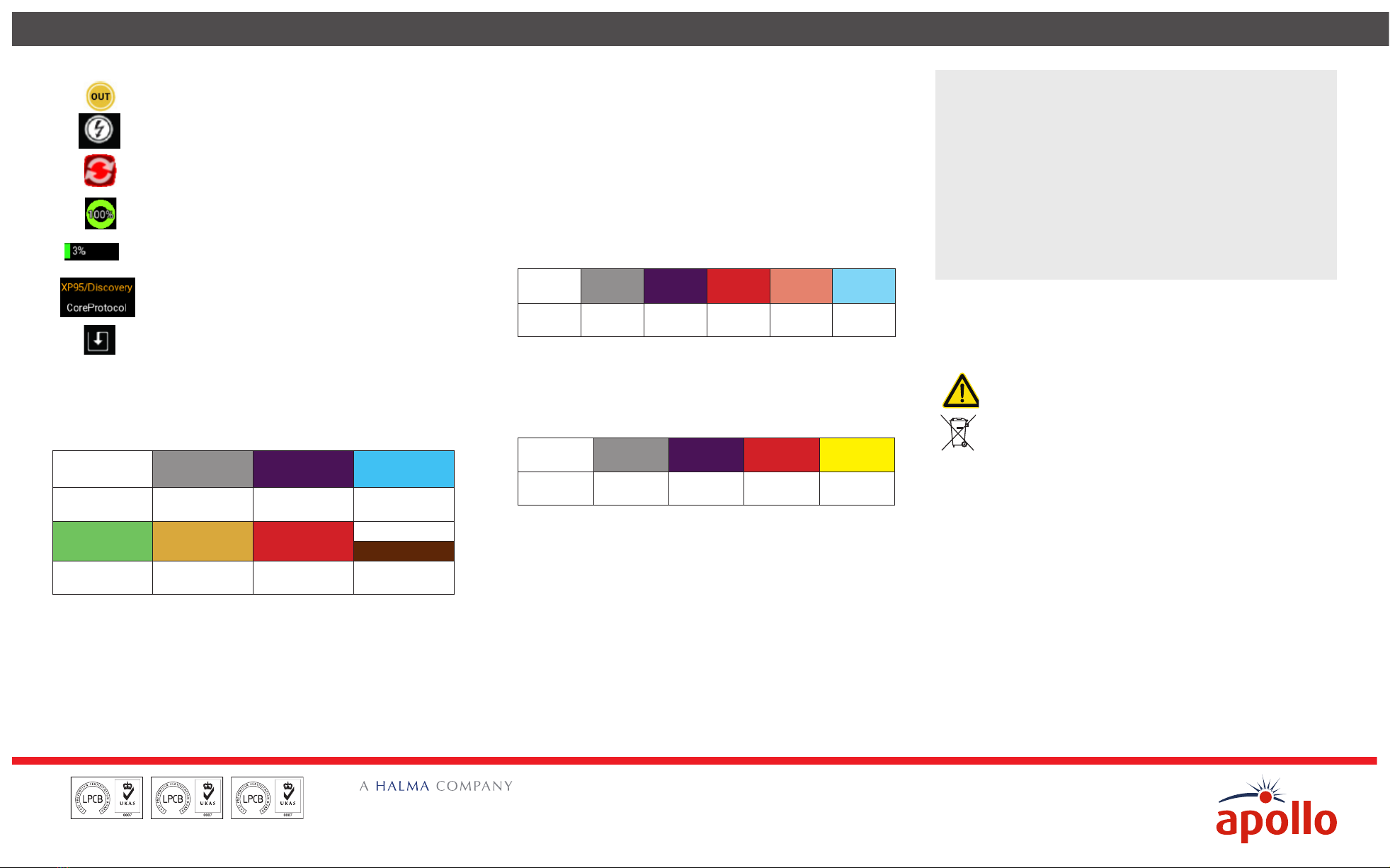
What do the Function Bar symbols mean?
Direction enabled/disabled - to change the current
state, tap on the icon
Voltage 28 V/35 V - tap the icon to switch voltages
(CoreProtocol only)
Sounder synchronisation - tap to synchronise
The loop health is shown as a percentage based on
address confirmation, a parity bit and checksum
The loop noise is shown as a percentage based on
current pulse amplitude
Switching between XP95/Discovery and CoreProtocol
digital communications protocols.
Tap to Save Loop Report/Loop Configuration (only
available in Control and Status - Mode and Polling
LED)
What can I access from the Loop View tab?
The Loop view menu consists of six sub-menus which use the colours that
follow to dierentiate the addresses:
Corrupt Data Empty Address Dual Address Analogue Value
≤ 8
8< Analogue
Value ≤ 44
45 ≤ Analogue
Value ≤ 54
Analogue Value
≥ 55 Drift Value > 30
The six sub-menus enable access to:
• Address Scan
The Address Scan menu enables you to view the devices connected to
the test set and review their type and status.
• Analogue Value/Drift
The Analogue Value/ Drift menu enables you to view and monitor the
analogue and drift values of each of the devices.
• Mode and Polling LED
The Mode and Polling LED menu enables you to view the modes and
the polling LED status of the devices connected to the test set. This
menu also enables you to save the loop configuration.
• Control and Status
The Control and Status menu enables you to view and control the
output and input bits of each of the devices and save a loop report.
• Events
The Events Menu enables you to view events flags, event types and
event addresses. Once you access the event log menus the recording
of events starts.
Occupied
Address
Empty
Address
Dual
Address
Tamper
Event
Alarm
Event
Fault
Event
• Data Log
The Data Log menu enables you to view the results of comparing the
connected devices initial frame and their current frame. Dierent
colours account for changes on each address. Once you have accessed
the Data Log menu the recording of data logs for each address begins.
Occupied
Address
Empty
Address
Dual
Address
Mismatched
Data Event Flag
• Pollong Range selection
As default, all addresses are polled - 126 for XP95/Discovery and
254 for CoreProtocol. You can choose to poll a selection of devices if
necessary. To enable this on Loop View you need to press and hold the
starting address in your selection, then slide to the last device in the
required range. The selected polling range will then be highlighted.
To return to whole loop view you need to tap outside of your selected
polling range.
The information in this Quick Start Guide is to let you start using the
Apollo Test Set as soon as you can. For a full explanation of how to use
the Test Set please visit the relevant product page of the Apollo website,
www.apollo-fire.co.uk, where you will find the complete User Manual
available for download.
What Technical Information do I need?
Power source Lithium-ion battery pack or 12 V dc
power supply unit
Li-ion battery pack Nomimal voltage: 7.4 V
Nominal capacity: 5200 mAh
Battery charging time Approx 3 hours
Operating temperature 0ºC to 40ºC
Humidity (no condensation
or icing)
10% to 95% RH
Dimensions 215 mm x 165 mm x 50 mm
Weight 935 g
Can I maintain or repair the Test Set?
The Apollo Test Set contains no User serviceable parts. However, a
replacement lithium-ion battery pack is available from Apollo.
CAUTION: Risk of explosion if battery is replaced by an
incorrect type
Do not dispose of batteries in domestic waste
Do not disassemble the Test Set as this may result in irreperable damage
and invalidate your Warranty.
Where can I get Technical Support?
You can get Technical Support from any of these:
Tel: +44 (0)23 9244 2706
Email: techsalesemails@apollo-fire.com
Website: www.apollo-fire.co.uk
Apollo Fire Detectors Ltd
36 Brookside Road
Havant
Hampshire. UK
PO9 1 JR
© Apollo Fire Detectors Ltd 2017
Other Apollo Test Equipment manuals


