Hioki 8860-50 User manual

MEMORY HiCORDER
8860-50, 8861-50
New Recording Logger and Oscilloscope
New REC&MEM Function
These models feature personal computer-like operability with mouse and key-
board support, accelerated by internal high-speed hardware that provides sim-
pler, faster operation. The Memory function monitors fast waveforms as easily
as an oscilloscope while the Logger function records trend graphs in real time.
Convenience is improved by enhanced control via LAN and USB capabilities.
A broad selection of plug-in front-end modules supports a wide variety of mea-
surement objects. Abnormal phenomena are accurately captured with 20 MS/s
sampling and 16-bit resolution on isolated inputs.

22
As an Oscilloscope
As a Data Logger
Record Waveforms in Any Situation
Model 8860-50/8861-50 Series Debut!

3
Capabilities and Features
20 MS/s high-speed sampling
Up to 32 isolated input channels (high-speed signals)
Real-time saving to hard disk
Dual-timebase sampling for simultaneous fast and slow monitoring
Multi-channel logging on up to 128 channels (low-speed signals)
Enhancements from Earlier Models 8860 and 8861
lA faster CPU greatly enhances instrument operability and response.
lThree USB 2.0 ports support a USB storage device along with mouse
and keyboard.
lNew REC&MEM (Recorder and Memory) function.
Capture waveforms of high-speed transients while simultaneously re-
cording at slow speed.
lNew LCD with wider viewing angle for easier waveform observation.
lUses the same input modules as previous models.
lSupports the new high-voltage input module for measuring
high voltage directly.
8860-50 side view 8861-50 side view
See page 4
See page 5
See page 6
See page 6
See page 10
See page 5
See page 4
3

44
A/D
conversion
Using the same operating principle as a digital oscilloscope, data is recorded to
the expanded internal memory at high speed. Sampling rate is up to 20 MS/s
(50-ns period) for all channels simultaneously. Capture unpredictable operating
anomalies and transient waveforms.
n Records to Solid-State Memory
Because instruments that rely on disk access such as hard disk drives are sus-
ceptible to vibration, they are often unsuitable for on-board measurements.
MEMORY HiCORDERs are preferable for on-board testing because they write
data to solid-state memory with no moving parts. You can back up data to a PC
Card or USB storage device when finished measuring. When the optional mem-
ory backup unit is installed, the instrument’s internal memory data is preserved
when power is turned off.
n All Channels Isolated, 20 MS/s Sampling
Except when using the Scanner Module, every input channel has
its own A/D converter. Because all channels are sampled simul-
taneously, transient waveforms can be easily observed along with
signals. The Scanner Module switches all inputs through a single
A/D converter, but even in that case, all channels are isolated.
n Large Capacity Internal Memory
Both high-speed write capability and a large memory capacity are
provided to support high-speed sampling. Total memory capac-
ity ranges from 32 megawords to 1 gigaword, enabling capture
of waveform peaks by high-speed sampling, as well as long-term
recording and long-period waveform capture. (Model 8861-50 provides
twice the memory capacity, but with the same recording time limits.)
n
An Actual Waveform
Measurement Example
For operational analysis of an inverter, the waveforms of the high fre-
quency switched carrier and the low frequency fundamental both need
to be observed. High-speed sampling, long-term memory recording
and input isolation make these observations possible. Various HIOKI
non-contact clamp-on sensors capable of measuring up to HF ranges
can be used to observe current waveforms.
CLAMP ON PROBE 3270 Series provides flat electrical
characteristics for observing current waveforms over a
remarkably broad range of amplitudes from mA order to
500 A at frequencies from DC to HF.
Memory Function for High-Speed Waveform Monitoring
Three-Phase Inverter Output Circuit
(Because emitter voltage for each phase is different, isolated measurements are essential.)
n Internal Memory Division (Segmentation) Function
Internal memory can be segmented for use into 4,096 blocks. By
using “sequential save” to write data to the segmented memory,
the waveform in any block can be overlaid with that in a reference
block for comparison.
n External Sampling Input Capability
The sampling rate for memory recording can be synchronized to
an external clock signal (up to 10 MS/s). So, for example, sampling
can be synchronized to the rotation cycle of an engine.
Reliably capture waveform anomalies buried within normal signals
- Memory (Digital Oscilloscope) Function -
A/D
conversion
Isolation
Isolation
Write on
memory
Display
Thermal Printer
Input signal
Input signal
Sampling period
Time Output waveform
Input signal
n High-Voltage
Measurement
Measuring in situations where high voltage exists between channels,
such as three-phase inverters, requires a measurement instrument that
has all input channels isolated. In addition, when measuring signals
such as those of switching circuits that include common-mode volt-
age with a high-frequency component, the isolated circuit’s common-
mode frequency rejection characteristics can greatly affect measure-
ments. To measure these kinds of voltages, you can use the HIGH
VOLTAGE UNIT 8961 or the optional DIFFERENTIAL PROBE 9322 for
CAT III 600-volt AC and DC maximum ratede voltage to earth.
HIGH VOLTAGE UNIT 8961
DIFFERENTIAL PROBE 9322

5
Simultaneous Long-Term Monitoring and Transient Recording (REC&MEM)
Recording Directly to Hard Disk or Other Storage Media (Real-Time Save)
n Maximum recording time for REC&MEM function
Timebase
Sampling
Period
No. of recording channels
Max. recording time (typical)
HDD PC card HDD PC card (512 MB)
5μs/DIV to 50μs/DIV
- abbreviated -
not applicable not applicable not applicable not applicable
100 μs/DIV
1μs1ch
not applicable
8h 19min 17s
not applicable
200 μs/DIV
2μs1ch
not applicable
16h 38min 34s
not applicable
500 μs/DIV
5μs2ch 1ch 20h 48min 10s 20min 55s
1 ms/DIV
10μs4ch 2ch 20h 48min 10s 20min 40s
2 ms/DIV
20μs10ch 4ch 16h 38min 20s 20min 20s
5 ms/DIV
50μs24ch 8ch 17h 17min 30s 24min 20s
10 ms/DIV
100μs33ch 20ch 1day 1h 8min 20s 16min 40s
20 ms/DIV
200μs33ch 33ch 2days 2h 16min 40s 16min 40s
50 ms/DIV to 5 min/DIV
- abbreviated - - abbreviated -
- abbreviated - - abbreviated - - abbreviated -
• Conditions:theharddisk orPC Cardhavejustbeenformatted,and anyrecording length settingisset to
maximum.Thetimebase of thewhole (compressed) waveformis setautomatically, andtheupperlimitof
recordingtimeisoneyear
• Recordingtimedependsontheformattedcapacityoftherecordingmediaand itsavailablecapacity,with
theabovebeingjustoneexample.
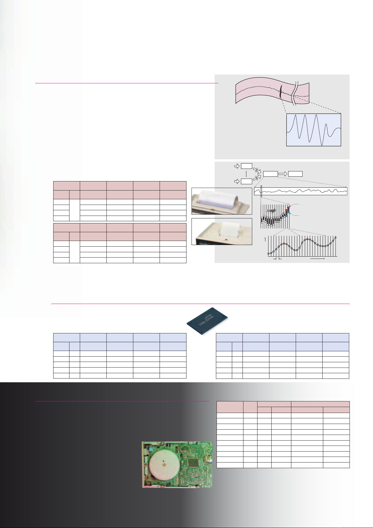
Capture High-Speed Signals by Triggering During Slow Recording
- New REC&MEM Function and Real-Time Saving -
n Transient waveform recording that is impossible with a pen recorder
The new REC&MEM function can record high-speed waveforms such as inter-
mittent noise by applying a trigger while recording long-term fluctuations just
like a pen recorder. This type of measurement previously required choosing
between the Recorder function (for slow trend graph recording), or the Memory
function (for high-speed oscilloscope-style recording). Now both types of wave-
forms can be recorded simultaneously using the REC&MEM function.
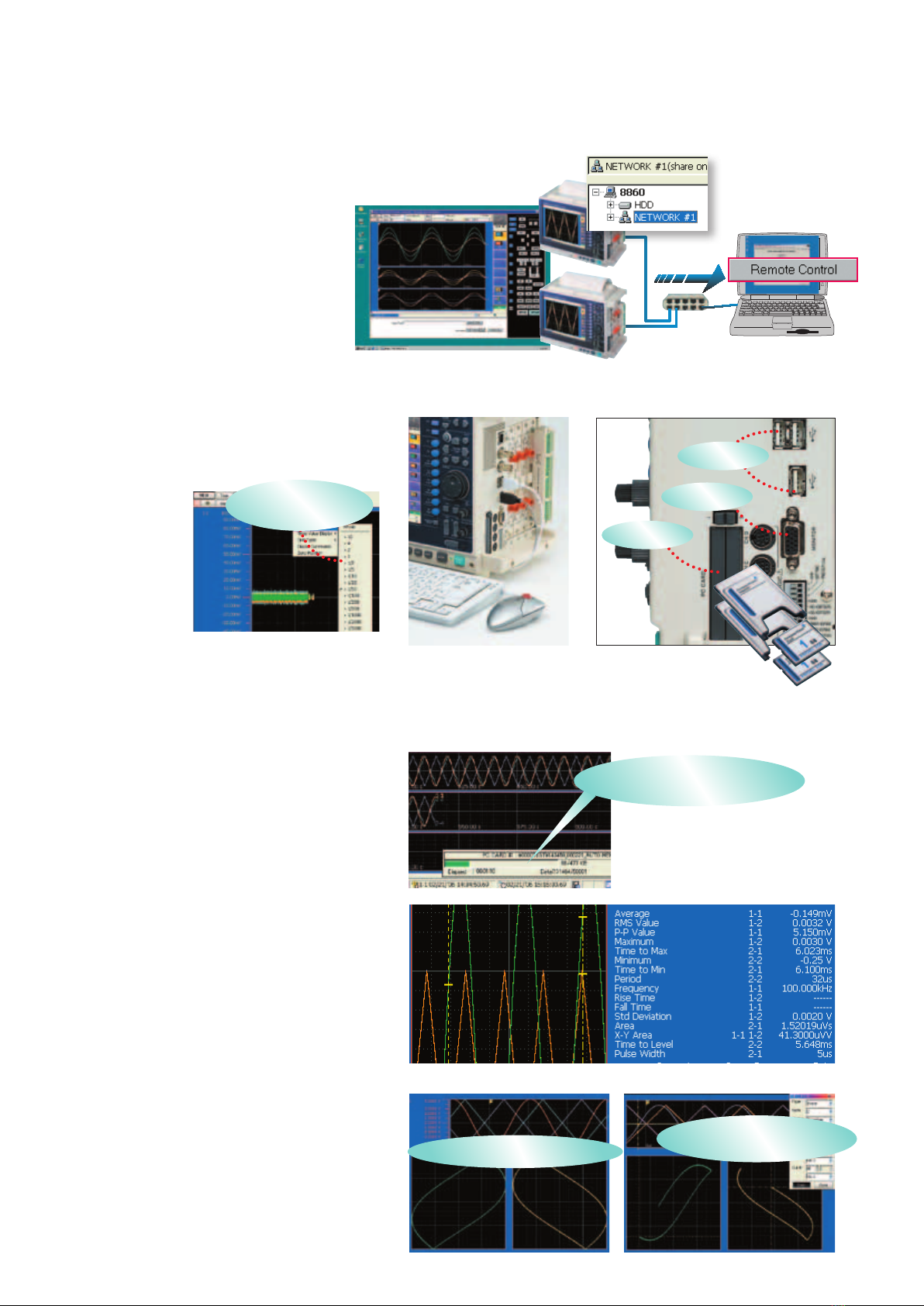
n Recording an Entire Waveform Anomaly
The Real-Time Save function writes measurement data to the specified des-
tination during measurement, enabling long-term measurements indepen-
dent of the instrument’s installed memory capacity. The destination storage
media may be the internal hard disk, a PC Card or a shared network folder.
Simultaneously, overall measurement data
(the whole waveform) is recorded in the
instrument’s internal memory, which is then
saved to the storage media when measure-
ment is finished. For analysis, specify the
range to be analyzed from the overall wave-
form data, and reload it. The reloaded data
is used with the Memory function for wave-
form and numerical calculations, or with the
FFT function for FFT analysis.
Without Scanner
Unit 8958
Memory capacity
32 M-words
Memory capacity
128 M -words
Memory capacity
512 M -words
Memory capacity
1 G-word
REC
Timebase
Sampling
Period
2,000 div 10,000 div 40,000 div 80,000 div
100 ms/DIV
3min 20s 16min 40s
1h 06min 40s 2h 13min 20s
to 100ns to to to to
30 min/DIV to
41d 16h 208d 08h
- abbreviated - - abbreviated -
1 hr/DIV
83d 08h
- abbreviated - - abbreviated - - abbreviated -
With Scanner Unit
8958
Memory capacity
32 M-words
Memory capacity
128 M -words
Memory capacity
512 M -words
Memory capacity
1 G-word
REC
Timebase
Sampling
Period
500 div 2,000 div 10,000 div 20,000 div
100 ms/DIV
50s 3min 20s
16min 40s 33min 20s
to 100ns to to to to
30 min/DIV to
10d 10h 41d 16h 208d 08h - omitted -
1 hr/DIV
20d 02h 83d 08h
- abbreviated - - abbreviated -
n
Maximum recording time for REC&MEM function (Recorder waveform)
• Thesettingrangedependsoninstalledmemorycapacity,whetherMemoryDivisionisenabled,andwhether16-ChScannerUnit
8958 is installed.
• Recordinglength"Continuous"isnotavailablewith100to200ms/divtimebasesetting,andwiththeprinterenabled.
• Timebasesettingsfrom10ms/divto1s/divarenotavailablewhenusingA6PrinterUnit8995-01 and numerical value printing.
• WhenthesamplingperiodforRecordingandMemoryrecordingissetatthesametime.
• Operationcannotbeguaranteedwhenthetimeaxisislongerthanoneyear.
Memory Division is
enabled
Memory capacity
32 M-words
Memory capacity
128 M -words
Memory capacity
512 M -words
Memory capacity
1 G-word
MEM
Timebase
Sampling
Period
5,000 div 20,000 div 80,000 div 160,000 div
10 μs/DIV 100ns
50ms 200ms
800ms 1.6s
20 μs/DIV 200ns
100ms 400ms
1.6s 3.2s
50 μs/DIV 500ns
250ms 1s
4s 8s
to to to to to to
5 min/DIV 3.0s
17d 08h 40min 69d 10h 40min 277d 18h 40min
- abbreviated -
n
Maximum recording time for REC&MEM function (Memory waveform)
• The sett ing r ange dep end s on in stalled me mor y cap acity, an d whethe r Memo ry Divi sion is enable d.
Maximum recording length is available when Memory Division is disabled.
• Presence of 16-Ch S canner Unit 8958 has no effect (scanner module signals are not written to
internal memory for Memory waveforms).
• Operationcannotbeguaranteedwhenthetimeaxisislongerthanoneyear. • MinimumrecordinglengthisavailablewhenMemoryDivisionissetto1,024blocks.
With Memory
Division 1024 blocks
Memory capacity
32 M-words
Memory capacity
128 M -words
Memory capacity
512 M -words
Memory capacity
1 G-word
MEM
Timebase
Sampling
Period
3 div 15 div 60 div 140 div
10 μs/DIV 100ns
30μs 150μs 600μs
1.4ms
20 μs/DIV 200ns
60μs 300μs
1.2ms 2.8ms
50 μs/DIV 500ns
150μs 750μs
3ms 7ms
to to to to to to
5 min/DIV 3.0s
15min 1h 15min 5h 00min 11h 40min
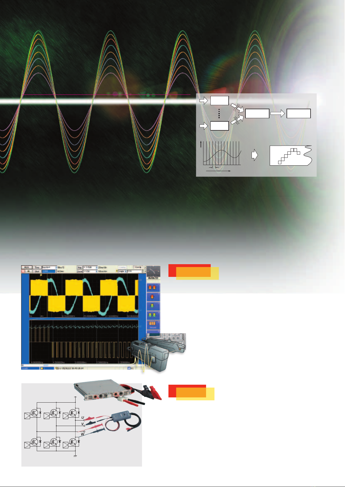
n Operating Principle of the Recorder Function
With the Recorder function, only maximum and minimum values
of the data sampled within the specified timebase are written to
memory, so each recorded data point consists of a pair of values,
with 100 such points recorded for each waveform timebase division.
Because of this, the volume of recorded data is compressed while
following steep fluctuations of the measured input voltage.
Note: When data recorded with the Recorder function is viewed on a PC, both
minimumandmaximumvaluesappearasatimeseriesofdatapoints.
• Recordabletimeforstoragemediadependsontheinstrument'sinstalledmemorycapacity,andthetotal
andavailablecapacityofthemedia.Thewholewaveformisdisplayed inrealtime(andprinting isdis-
abled).
Note: ScannerUnit8958isnotused.
REC mode recording
Waveform envelopes recorded as
pairs of maximum and minimum
values
MEM mode recording
Waveform captured with high-speed sampling
A/D
conversion
Isolation
Write on
memory Display
Thermal Printer
Input signal
Input signal
Sampling period Time
Input signal
A/D
conversion
Write on
memory
A4 size Printer Unit
8995
A6 size Printer Unit
8995-01
Maximum value
Minimum value

66
Waveform Observation While Recording
n
Changing Compression and Zooming While Measuring
Models 8860-50 and 8861-50 support changing the compression ratio, turning
the zoom function on and off, and scroll-back display while measuring, so you
can view and analyze existing measurement data without having to wait for the
measurement process to finish.
n
Scroll-Back Display
An earlier portion of the waveform can be viewed without interrupt record-
ing. This function automatically displays earlier parts of the waveform just by
turning the Scroll knob counterclockwise. Click the Scroll Trace button on the
screen, to return the display to the current waveform position.
Sheet Display Function
The Sheet function has been introduced to support multi-channel
measurements (each sheet shows 32 channels). Different display
formats can be selected for each sheet, so that each sheet can be
assigned and analyzed for a particular application.
The Next Generation Hybrid Recorder
- A single instrument provides both oscilloscope and data logger functions -
Installing a Scanner Module Creates a Multi-Channel Data Logger
Recording slowly changing physical values such as temperature has been per-
formed by plotting recorders and hybrid recorders (combined numerical value
and analog graph recording), and is currently performed by data loggers. On
the other hand, for high-speed waveform observation, only an oscilloscope (or
MEMORY HiCORDER) can be used. However, because the demands of mea-
surement sites can vary, having both of these functions in a single instrument
can be advantageous.
MEMORY HiCORDER Models 8860-50 and 8861-50 and Scanner Unit 8958 are
the answer to customers’ needs.
The waveform scrolling direction can be switched between vertical
and horizontal. You can also view a continuously scrollable display to
confirm a whole long-term waveform without time-axis compression,
while simultaneously displaying time series’ and X-Y plots.
n Economical Cost per Channel
The Scanner Module switches 16 input channels through one A/D convert-
er. Of course all channels are isolated. Cost per channel is thereby remark-
ably reduced when compared to systems that include an A/D converter for
every input channel. Installing four Scanner Modules in the 8860-50 pro-
vides 64 measurement channels, and installing eight Scanner Modules in the
8861-50 provides 128 measurement channels.
n Dual-Timebase Sampling at High and Low Speeds
Depending on customers’ applications, there are cases in which high-speed
signals need to be captured as waveforms while measuring multiple chan-
nels with a Scanner Module. Both types of signals can be measured by using
a scanner module together with a common high-speed analog module, and
recording with two different timebases. Two waveforms are displayed and
can be monitored on the same time axis.
Second timebase, 1 sec sampling
(Same time axis with the rst timebase,
1 sec/div)
First timebase, 50 μsec sampling
(Compressed time axis 1/200, 1 sec/
div)
First timebase, 50 μsec sampling
(Numerical display)
Turn the scroll knob to
scroll back
Timeline and XY-axis composite waveformSix-split screen continuous scroll
Four-split screen vertical scroll

7
Trigger during capturing and search after capturing
The trigger function allows you to set diverse parameters to detect
a particular waveform anomaly during capturing. Setting the pre-
trigger mode allows you to monitor the pre-trigger waveform. This is
useful for analyzing the cause of the anomaly.
On the other hand, the search function allows you to detect an anom-
aly after all data is captured. This allows you to search for and display
an anomaly in the same manner as with the trigger function.
When a waveform is unpredictable and setting a parameter during
measurement is difficult, it is recommended to use the search func-
tion to locate an anomaly after capturing.
n Capture a sudden power loss with the drop trigger
Set the voltage drop trigger to capture a sudden power loss resulting from a blackout
caused by lighting or a circuit breaker tripping.
Set the window out trigger to capture an impulse noise or surge noise (voltage swell)
caused by, for example, the solenoid opening and closing.
Set multiple triggers on a single channel
Unlike with conventional MEMORY HiCORDERs, the 8860 series
allows you to set multiple trigger parameters on a particular single
channel. This allows you to set, for example, the glitch trigger, level
trigger, window-out trigger, voltage drop trigger, window-in trigger,
and on the same input wave-
form to monitor it. (8 parameters
in the 8860-50 and 16 param-
eters in the 8861-50 can be set.)
n Stop trigger for the MEM function
Unlike with conventional MEMORY HiCORDERs, a stop trigger is supported. This
enables the timing of measurement to be controlled for both the MEM and REC
functions. This also allows you to set Start or Stop independently for each trigger
source, thus enabling the timing of measurement to be controlled in a variety of com-
binations. (Start or Stop trigger can also be set to the logical source.)
n Slope trigger
Unlike with conventional MEMORY
HiCORDERs, a slope trigger is supported.
This allows you to monitor a noise super-
imposed on periodic waveforms such as
a power waveform. This also allows you
to monitor a rapid change in temperature
with the amount of change in slope instead
of level.
n Edge detection and level detection of the logic trigger
Unlike with conventional MEMORY HiCORDERs supporting only
edge detection, the Models 8860-50 and 8861-50 supports level detec-
tion of the logic trigger. This function causes the trigger to be activat-
ed when a specified pattern occurs, even if the logic pattern condition
is not met after the start of measurement.
n
Set the event times independently for each trigger source
* For the analog trigger only
Unlike with conventional MEMORY HiCORDERs, this
allows you to set the event times independently for each
trigger source, thus enabling the setting of trigger condi-
tions in a variety of combinations.
Accurately capture waveforms with diverse parameters
- Advanced trigger function -
A simple level trigger causes the
start trigger to be activated
The eighth level trigger causes the
stop trigger to be activated (in the
case of specifying the event times)
Power waveform noise Power waveform noise Rapid change in temperature
For edge detection of pattern “1, 0, 0, ↑
,” the
trigger is not activated in this position.
For edge detection, the trigger is not activated unless
the condition is not met after the start of measurement
For level detection, the trigger is activated only if
the condition is met after the start of measurement
In case of conventional edge detection
1
0
0
↑
1
0
0
↑1
0
0
↑
In case of level detection
The trigger event times for the
trigger source is set to 5.

8
n Change the settings on the DISP screen
The dialog bar on the top of the DISP screen (waveform monitor-
ing screen) allows you to change the settings.
The frequency resolution and capture time are also displayed.
FFT analysis function
The single-channel FFT function is used in spectrum analysis. The two-
channel FFT function analyzes transfer functions. The octave analysis func-
tion is used in acoustic analysis. The signal source for FFT analysis is a sec-
tion obtained from the waveforms captured in the MEM function (the required
number of pieces of data for FFT analysis are 1000 to 20,000 points). The
calculation speed for the same condition (when performing the most time-con-
suming analysis) is about ten times faster than with the conventional Model
8855.
n Simultaneously perform up to 16 calculations
Unlike with the conventional HIOKI 8855 and 8841 models that
allow for the simultaneous performing of up to two calculations,
the 8860-50 and 8861-50 models allow for the simultaneous
performing of up to eight (four times more) FFT calculations for
analysis. Furthermore, the analysis channel can be selected inde-
pendently.
n Split screen (a total of 14 patterns)
You can select a split screen for-
mat according to your needs. For
example, the MEM and REC func-
tions allow you to select a different
split screen format independently for
each sheet. Unlike with, for example,
the conventional 8855 and 8841
models, a function to display super-
imposed graphs is also supported
(however, the function depends on the analysis
mode).
n A variety of window functions
Unlike with the conventional 8855 and 8841 models that sup-
port only the three window function options “Rectangular,”
“Hanning,” and “Exponential,” the 8860-50 and 8861-50 mod-
els include four additional options, thus enabling you to select
a window function from a total of seven options. Furthermore,
a difference in calculation results of line spectrum between
other companies’ FFT analyzers and HIOKI’s analyzer can be
compensated by selecting the energy attenuation compensation
method when using a window function.
n Phase Highlight Display
Phase Highlight emphasizes on the display only those parts of a
waveform that exceed a certain level, in order to acquire a power
spectrum in the midst of phase calculation. The figure shows
power and phase spectra at the same time when the highlighted
display is enabled, so you can easily see important parts of the
waveform that are normally difficult to see because they appear
like noise.
Convert the time domain to the frequency domain for analysis
- FFT analysis function -
Time domain
Frequency domain

9
Perform FFT calculation on the waveform from the MEM function
When performing FFT analysis on the data obtained by measurement with the
MEM function, you can use the jog shuttle to specify an analysis point and view
the calculation results on the same screen. Unlike with the conventional 8855 and
8841 models, you do not need to switch between the MEM function and FFT func-
tion screens to set the starting point of calculation. Furthermore, the display of “Raw
Data” obtained by measurement with the MEM function and the calculation results
of“StorageWaveform”onthesamescreenallowsyoutoviewtheeffectofthewin-
dow function and the spectrum waveform on the same window, thus greatly enhanc-
ing operability for analysis.
Power spectrum density
You can obtain a power spec-
trum per Hz when analyzing
signals spread over a wide area,
such as noise.
Power spectrum density (LPC
analysis)
The most appropriate spec-
trum is estimated using the
statistical method.
1,000 points Convert 1,000 to 10,000 points
Before scaling
After scaling
n Rich Analysis Capabilities
Power Spectrum Density and LPC Analysis have been added to
the calculation selections, for measuring power spectrum per Hz
and spectral envelopes. As for calculation settings, former con-
cepts such as “Channel Modes” have been eliminated, and chan-
nel settings are now automatically set according to the selected
calculation type, eliminating otherwise complex settings.
n Change the count of calculation points and perform re-calculation
after measurement ends
After measurement is performed using less calculation points, you
can change the point count and perform re-analysis. For example, if
you perform measurement using 1,000 calculation points, you can
then convert point count to 20,000 to perform re-analysis on the data.
In this case, the frequency resolution increases 10 times. Needless to
say, you can convert the point count to 1,000 to perform re-analysis
on the data obtained by performing measurement using 20,000
points.
*Re-calculationbychangingthepointcountcannotbeperformedwhenMeanFrequencyissettoON.
n Scaling in “dB”
The long desired capability to scale in dB is supported. You no
longer need to perform logarithmic calculation holding a calcula-
tor in one hand. The 8860-50 and 8861-50 models allow you to
enter the overall value (sum of power spectrum values) in dB,
thus making scaling easier. This enables
signals to be easily read directly from, for
example, a noise meter.
Specify an analysis point
Waveform in the MEM function

10
n To access the shared folder:
Enter the host name of the computer on the file screen of the 8860-50, enter the user
name and password in the account field, and then select the folder you want to share.
n
Restrictions
Automatic saving during measurement is restrict-
ed to 1ms/division or more of the time axis. Also,
restrictions to the time axis settings differ depend-
ing on the scanner module, number of channels,
storage media, and setting conditions for real-time
printing.
n
Remote control and automatic saving to a shared folder
The 8860 series allows for remote control using
the Internet browser on the computer. When you
register access to a shared folder on a computer on
the network, you can store and load data to and from
the shared folder on the 8860-50 or the 8861-50 file
screen.
n USB Mouse and keyboard connectivity
With the Windows-style interface, you can easily make set-
tings and adjustments with the click of a mouse, and enter
text and other com-
ments with a keyboard
as you would on a
common PC.
n USB Ports and External Monitor Output
Three USB 2.0 ports are now provided to support commonly available
PC peripherals. A VGA D-sub output connector is also included to
support viewing the measurement screen on an external monitor.
n Automatic saving during measurement
Unlike with conventional MEMORY HiCORDERs, the 8860
series allows automatic saving during measurement.
n
Redundancy against errors in the storage destination
The 8860 series allows you to set up to two storage destina-
tions. Even if, for example, an overflow error occurs on a PC card during
automatic saving, switching to the second backup storage destination
takes place automatically to ensure saving continues.
n Set 16 groups of numerical calculations
Unlike with conventional MEMORY HiCORDERs, the 8860
series allows you to set 16 groups of numerical calculations.
Furthermore, each group allows you to select 16 calculation items
from a total of 19. The SUB MENU screen of the waveform
screen also allows you to view and change the numerical calcu-
lation settings and perform recalculation. This enables the set-
tings of calculations in each group on the waveform screen to be
changed and monitored, thus enhancing operability.
n
Simultaneously display timeline and XY-axis composite waveforms
The 8860 series uses a split screen to support the simultaneous
display of “timeline waveform” and “XY-axis composite wave-
form.” Any channel can be set to the X-axis and Y-axis. The
MEM function supports XY-axis waveforms. Models 8860-50
and 8861-50 can display sixteen X-Y plots simultaneously.
Remote control with the Internet browser
- LAN/USB, calculation function -
Access a variety of pop-
up menus with a right-
click of the mouse.
USB receptacle A
3 ports
External monitor
output
PC card type II
2 slots
Automatic saving during measurement
shortens the waiting time for saving
after measurement ends
You can simultaneously display the timeline waveform
and up to two XY-axis composite waveforms.
The simultaneous display of the timeline screen
facilitates combining the X-axis and Y-axis wave-
forms between cursor points A and B.

11
Basic specications
8860-50 (max. 4 input modules) 8861-50 (max. 8 input modules)
Input type/number of
channels
Plug-in input modules
Max. 16 analog channels (max. 64
channels with scanner unit) + 16 logic
channels (standard configuration)
Plug-in input modules
Max. 32 analog channels (max. 128
channels with scanner unit) + 16 logic
channels (standard configuration)
Measurement
functions
MEM (high-speed recording)
REC (real-time recording)
REC & MEM (real-time recording + high-speed recording)
FFT (frequency analysis)
Real-time Save (records directly to storage media)
Maximum
sampling rate
20 MS/second (50 ns, all channels simultaneously, using the ANALOG UNIT 8956)
External sampling (10 MS/second, 100 ns)
Types of measurement
signals
Highest sampling rate and
resolution
(Model number of input module
shown in parentheses)
1 unit: Voltage 2ch, 20 MS/s, 12-bit resolution (8956)
1 unit: Voltage 2ch, 2 MS/s, 16-bit resolution (8957)
1 unit: Voltage / Thermocouple scan 16ch, max. 50 ms refresh rate, 1/1000 of range
resolution for temperature axis - (8958)
1 unit: Voltage / RMS, 1 MS/s, 12-bit resolution (8959)
1 unit: Voltage / RMS, 2 MS/s, 16-bit resolution (8961)
1 unit: Voltage 2ch, 1 MS/s, 12-bit resolution (8936/8938)
1 unit: Voltage / Thermocouple 2ch, 4 kS/s, 12-bit resolution (8937)
1 unit: Strain gauge 2ch, 1 MS/s, 12-bit resolution (8939)
1 unit: Strain gauge 2ch, 200 kS/s, 16-bit resolution (8960)
1 unit: Frequency / Integration / Current / Voltage 2ch, 1 MS/s, 12-bit resolution (8940)
1 unit: Accelerometer 2ch, 1 MS/s, 12-bit resolution (8947)
1 unit: Voltage 4ch, 1 MS/s, 12-bit resolution (8946)
Direct access internal
memory
*1
Factory installation only: select
1 board for the 8860-50, and
2 of the same capacity for the
8861-50 when ordering.
9715-50: 32 Megawords
9715-51: 128 Megawords
9715-52: 512 Megawords
9715-53: 1 Gigaword
32 Mega-words (MEMORY BOARD 9715-50 ×1)
(analog 12-bit + logic 4-bit) × 32 Mega-words/
ch (using 1 channel) to (analog 12-bit + logic
4-bit) × 2 Mega-words/ch (using 16 channels)
1 Giga-word (MEMORY BOARD 9715-53 ×1)
(analog 12-bit + logic 4-bit) × 1 Giga-word/
ch (using 1 channel) to (analog 12-bit + logic
4-bit) × 64 Mega-words/ch (using 16 channels)
64 Mega-words (MEMORY BOARD 9715 -50 ×2)
(analog 12-bit + logic 4-bit) × 32 Mega-words/
ch (using 2 channels) to (analog 12-bit + logic
4-bit) × 2 Mega-words/ch (using 32 channels)
2 Giga-words (MEMORY BOARD 9715-53 ×2)
(analog 12-bit + logic 4-bit) × 1 Giga-word/ch
(using 2 channels) to (analog 12-bit + logic
4-bit) × 64 Mega-words/ch (using 32 channels)
Note:1word=2bytes(12-bitsor16-bits),therefore1giga-word=2giga-bytes.
Note:Internalmemoryisallocateddependingonthenumberofchannelsused.
Data storage media
*2 Factory installation only
PC Card Type II slot (standard) ×2: up to 4GB (Flash ATA), FAT, or FAT-32
format supported
Hard disk drive (option, HD UNIT 9718-50 *2)×1: 80GB, FAT-32 format
Basic specications
8860-50 (max. 4 input modules) 8861-50 (max. 8 input modules)
Backup functions
*3 Factory installation only -
please specify upon order the
MEMORY BACKUP UNIT
9719 -50
The following items are preserved on the memory board(s) even after power off:
Clock and parameter setting backup (standard):at least 10 years; at
reference temperature (25°C)
Waveform backup function (using optional Model 9719-50 *3):10 hours (8860-50)
or 5 hours (8861-50), after full charge, at reference temperature (25°C)
External control
connectors
BNC connectors: external sampling input, sampling sync output
Terminal block: external trigger input, trigger output, GO/NG
output, external start, external stop, print input
Calibrator Output
Terminal Block: Select either Trigger Output, or CAL Output to
provide a 0/5 V, 1-kHz square wave for adjusting compensation
for the intrinsic capacitance of 10:1 and 100:1 probes.
Standard external
interfaces
*4 Using PC Card slot and Contec
GP-IB card GP-IB (CB) FL
USB: USB2.0 compliant, series A receptacle 3 ports (keyboard, mouse,
HDD, USB-memory), Note:CompatibleExternalUSBprinterisdiscontinued,so
USBprinterisN/A
LAN: RJ-45 connector, Ethernet 100BASE-TX, 10BASE-T
Functions: HTTP server, FTP server, File sharing, DHCP compatible,
Send mail
Monitor output: 15-pin D-sub connector, SVGA output
GP-IB *4: Not Available as Contec GP-IB Card is discontinued
Environmental conditions
(no condensation)
Temperature and humidity range for use: 0°C to 40°C, 20% to 80% RH
Temperature and humidity range for storage: -10°C to 50°C, 20% to 90% RH
Compliance
standard
Safety: EN61010,
EMC: EN61326, EN61000-3-2, EN61000-3-3
Power
requirements
100 to 240 V AC (50/60 Hz)
12 V DC (usetheDCPOWERUNIT9684 : option, factory installation only)
Power
consumption
220 VA max. (printer not used)
300 VA max. (A4 printer used)
280 VA max. (printer not used)
350 VA max. (A4 printer used)
Dimensions and
mass
Approx. 330 mm (12.99 in)W×250 mm
(9.84 in) H ×184.5 mm (7.26 in) D, 8 kg
(282.2 oz) (printer not installed)
Approx. 330 mm (12.99 in)W×272.5 mm
(10.73 in) H ×184.5 mm (7.26 in) D, 9.5 kg
(335.1 oz) (A4 printer installed)
Approx. 330 mm (12.99 in)W×255.5 mm
(10.06 in) H ×184.5 mm (7.26 in) D, 9.0 kg
(317.5 oz) (A6 printer installed)
Approx. 330 mm (12.99 in)W×250 mm
(9.84 in) H ×284.5 mm (11.20 in) D, 10.5 kg
(370.4 oz) (printer not installed)
Approx. 330 mm (12.99 in)W×272.5 mm
(10.73 in) H ×284.5 mm (11.20 in) D, 12 kg
(423.3 oz) (A4 printer installed)
Approx. 330 mm (12.99 in)W×255.5 mm
(10.06 in) H ×284.5 mm (11.20 in) D, 11.5
kg (405.6 oz) (A6 printer installed)
Supplied
accessories
Quick Start Manual ×1, Instruction Manual ×1, Input Module Guide ×
1, Analysis Supplement Manual ×1, Power cord ×1, Input cord label
×1,ApplicationDisk(WaveViewerWv,CommunicationCommands
table) ×1
Only First
Timebase
No.of
used CH
8860-50 : 16ch
8861-50 : 32ch
8860-50 : 8ch
8861-50 : 16ch
8860-50 : 4ch
8861-50 : 8ch
8860-50 : 2ch
8861-50 : 4ch
8860-50 : 1ch
8861-50 : 2ch
Memory
capacity
32MW 20,000 div 40,000 div 80,000 div 160,000 div 320,000 div
128MW ×4 (80,000 div) ×4 (160,000 div) ×4 (320,000 div) ×4 (640,000 div) ×4 (1,280,000 div)
512MW ×16 (320,000 div) ×16 (640,000 div) ×16 (1,280,000 div) ×16 (2,560,000 div) ×16 (5,120,000 div)
1GW ×32 (640,000 div) ×32 (1,280,000 div) ×32 (2,560,000 div) ×32 (5,120,000 div) ×32 (10,240,000 div)
Time axis
Sampling
Period
32MW
20,000 div
32MW
40,000 div
32MW
80,000 div
32MW
160,000 div
32MW
320,000 div
5μs/DIV 50ns
100ms 200ms 400ms 800ms 1.6s
10μs/DIV 100ns
200ms 400ms 800ms 1.6s 3.2s
20μs/DIV 200ns
400ms 800ms 1.6s 3.2s 6.4s
50μs/DIV 500ns
1s 2s 4s 8s 16s
100μs/DIV 1μs
2s 4s 8s 16s 32s
200μs/DIV 2μs
4s 8s 16s 32s 1min 04s
500μs/DIV 5μs
10s 20s 40s 1min 20s 2min 40s
1ms/DIV 10μs
20s 40s 1min 20s 2min 40s 5min 20s
2ms/DIV 20μs
40s 1min 20s 2min 40s 5min 20s 10min 40s
5ms/DIV 50μs
1min 40s 3min 20s 6min 40s 13min 20s 26min 40s
10ms/DIV 100μs
3min 20s 6min 40s 13min 20s 26min 40s 53min 20s
20ms/DIV 200μs
6min 40s 13min 20s 26min 40s 53min 20s
1h 46min 40s
50ms/DIV 500μs
16min 40s 33min 20s
1h 06min 40s 2h 13min 20s 4h 26min 40s
100ms/DIV 1ms
33min 20s
1h 06min 40s 2h 13min 20s 4h 26min 40s 8h 53min 20s
200ms/DIV 2ms
1h 06min 40s 2h 13min 20s 4h 26min 40s 8h 53min 20s 17h 46min 40s
500ms/DIV 5ms
2h 46min 40s 5h 33min 20s 11h 06min 40s 22h 13min 20s
1d 20h 26min 40s
1s/DIV 10ms
5h 33min 20s 11h 06min 40s 22h 13min 20s
1d 20h 26min 40s 3d 16h 53min 20s
2s/DIV 20ms
11h 06min 40s 22h 13min 20s
1d 20h 26min 40s 3d 16h 53min 20s 7d 09h 46min 40s
5s/DIV 50ms 1d 03h 46min 40s 2d 07h 33min 20s 4d 15h 06min 40s 9d 06h 13min 20s 18d 12h 26min 40s
10s/DIV 100ms 2d 07h 33min 20s 4d 15h 06min 40s 9d 06h 13min 20s 18d 12h 26min 40s 37d 00h 53min 20s
30s/DIV 300ms 6d 22h 40min 00s 13d 21h 20min 00s 27d 18h 40min 00s 55d 13h 20min 00s 111d 02h 40min 00s
1min/DIV 600ms 13d 21h 20min 00s 27d 18h 40min 00s 55d 13h 20min 00s 111d 02h 40min 00s 222d 05h 20min 00s
100s/DIV 1.0s 23d 03h 33min 20s 46d 07h 06min 40s 92d 14h 13min 20s 185d 04h 26min 40s 370d 08h 53min 20s
2min/DIV 1.2s 27d 18h 40min 00s 55d 13h 20min 00s 111d 02h 40min 00s 222d 05h 20min 00s - abbreviated -
5min/DIV 3.0s 69d 10h 40min 00s 138d 21h 20min 00s 277d 18h 40min 00s - abbreviated - - abbreviated -
n Maximum Recording Time for the Memory Function (single timebase)
• One Memor y Board Model 9715-50 is installed in the 8860-50, and two in the 8861-50, recording length variable,
with32-MWords.
• Operationcannotbeguaranteedwhenthetimeaxisislongerthanoneyear.
• Formemorycapacity,32MWordsisstandardasshowninthetablebelow.Optionalmemoryupto1GWordcanbespeci-
fied when ordering.
First
Timebase
No.of
used CH
8860-50 : 16ch
8861-50 : 32ch
8860-50 : 8ch
8861-50 : 16ch
8860-50 : 4ch
8861-50 : 8ch
8860-50 : 2ch
8861-50 : 4ch
8860-50 : 1ch
8861-50 : 2ch
Second
Timebase
No.of
used CH
at 8958
8860-50: 8 x 8ch
8861-50: 16 x 8ch
8860-50: 8 x 8ch
8861-50: 16 x 8ch
8860-50: 4 x 8ch
8861-50: 8 x 8ch
8860-50: 2 x 8ch
8861-50: 4 x 8ch
8860-50: 1 x 8ch
8861-50: 2 x 8ch
Memory
capacity
32MW 1,000 div 2,000 div 5,000 div 10,000 div 20,000 div
128MW ×5 (5,000 div) ×5 (10,000 div) ×4 (20,000 div) ×4 (40,000 div) ×4 (80,000 div)
512MW ×20 (20,000 div) ×20 (40,000 div) ×16 (80,000 div) ×16 (160,000 div) ×16 (320,000 div)
1GW ×40 (40,000 div) ×40 (80,000 div) ×32 (160,000 div) ×32 (320,000 div) ×32 (640,000 div)
Time axis
Sampling
Period
32MW
1,000 div
32MW
2,000 div
32MW
5,000 div
32MW
10,000 div
32MW
20,000 div
5μs/DIV 50ns
5ms 10ms 25ms 50ms 100ms
10μs/DIV 100ns
10ms 20ms 50ms 100ms 200ms
20μs/DIV 200ns
20ms 40ms 100ms 200ms 400ms
50μs/DIV 500ns
50ms 100ms 250ms 500ms 1s
100μs/DIV 1μs
100ms 200ms 500ms 1s 2s
200μs/DIV 2μs
200ms 400ms 1s 2s 4s
500μs/DIV 5μs
500ms 1s 2.5s 5s 10s
1ms/DIV 10μs
1s 2s 5s 10s 20s
2ms/DIV 20μs
2s 4s 10s 20s 40s
5ms/DIV 50μs
5s 10s 25s 50s 1min 40s
10ms/DIV 100μs
10s 20s 50s 1min 40s 3min 20s
20ms/DIV 200μs
20s 40s 1min 40s 3min 20s 6min 40s
50ms/DIV 500μs
50s 1min 40s 4min 10s 8min 20s 16min 40s
100ms/DIV 1ms
1min 40s 3min 20s 8min 20s 16min 40s 33min 20s
200ms/DIV 2ms
3min 20s 6min 40s 16min 40s 33min 20s
1h 06min 40s
500ms/DIV 5ms
8min 20s 16min 40s 41min 40s
1h 23min 20s 2h 46min 40s
1s/DIV 10ms
16min 40s 33min 20s
1h 23min 20s 2h 46min 40s 5h 33min 20s
2s/DIV 20ms
33min 20s
1h 6min 40s 2h 46min 40s 5h 33min 20s 11h 06min 40s
5s/DIV 50ms
1h 23min 20s 2h 46min 40s 6h 56min 40s 13h 53min 20s
1d 03h 46min 40s
10s/DIV 100ms
2h 46min 40s 5h 33min 00s 13h 53min 20s
1d 03h 46min 40s 2d 07h 33min 20s
30s/DIV 300ms
8h 20min 00s 16h 40min 00s
1d 17h 40min 00s 3d 11h 20min 00s 6d 22h 40min 00s
1min/DIV 600ms
16h 40min 00s 33h 20min 00s
3d 11h 20min 00s 6d 22h 40min 00s 13d 21h 20min 00s
100s/DIV 1.0s 1d 03h 46min 40s 2d 07h 33min 20s 5d 18h 53min 20s 11d 13h 46min 40s 23d 03h 33min 20s
2min/DIV 1.2s 1d 09h 20min 00s 2d 18h 40min 00s 6d 22h 40min 00s 13d 21h 20min 00s 27d 18h 40min 00s
5min/DIV 3.0s 3d 11h 20min 00s 6d 22h 40min 00s 17d 08h 40min 00s 34d 17h 20min 00s 69d 10h 40min 00s
n Maximum Recording Time for the Memory Function (dual timebase)
• One Memor y Board Model 9715-50 is installed in the 8860-50, and two in the 8861-50, recording length variable,
with32-MWords.
• Operationcannotbeguaranteedwhenthetimeaxisislongerthanoneyear.
• Formemorycapacity,32MWordsisstandardasshowninthetablebelow.Optionalmemoryupto1GWordcanbespeci-
fied when ordering.
n
Main unit Specifications (Accuracy guaranteed for 1 year, Post-adjustment accuracy guaranteed for 1 year)

12
Print/display section
*6Printer functions are available when optional
printer unit
is installed
Display 10.4 inch TFT color LCD (SVGA, 800 × 600 dots)
*6
Recording paper
RECORDING PAPER 9231: 216 mm (8.50 in) × 30 m (98.43 ft),
thermal paper roll (when using A4-size the printer unit 8995)
RECORDING PAPER 9234: 112 mm (4.41 in) × 18 m (59.06 ft),
thermal paper roll (when using A6-size the printer unit 8995-01)
*6
Recording width
RECORDING PAPER 9231: 200 mm (7.87 in) , full scale 20 divisions, 1
division = 10 mm
(0.39 in)
(when using A4-size the printer unit 8995)
RECORDING PAPER 9234: 100 mm
(3.94 in)
, full scale 10 divisions,
1 division = 10 mm
(0.39 in)
(when using A6-size the printer unit 8995-01)
*6
Paper feed density
10 lines/mm (when using A4-size the printer unit 8995 ), 8 lines/mm
(when using A6-size the printer unit 8995-01)
*20lines/mmwith"smoothedprinting"memoryfunction(whenusingA4-sizetheprinterunit8995)
*6
Recording speed
Max. 25 mm (0.98 in)/sec
Trigger functions
Trigger sources
Turn on/off independently for each trigger source of analog/logic A – D,
external trigger (a rise of 2.5V or terminal short circuit); timer trigger,
inter-source AND/OR, forced trigger,
standard mode (trigger source to all analog channels settable), extend
mode (multiple analog sources to a single analog channel settable, up
to 8 for 8860-50, and up to 8 on channels/units 1 – 4, and up to 8 on
channels/units 5 – 8 for 8861-50 settable)
Trigger types
(analog)
Level: Triggering occurs when preset voltage level is crossed
(upwards or downwards).
Window: Triggering occurs when window defined by upper and
lower limit is entered or exited.
Period: Rising edge or falling edge cycle of preset voltage value
is monitored and triggering occurs when defined cycle range is
exceeded.
Glitch: Triggering occurs when pulse width from rising or falling
edge of preset voltage value is underrun.
Slope: Triggering occurs when preset change degree (slope) is
exceeded or underrun.
Voltage drop: Triggering occurs when voltage drops below peak
voltage setting (for 50/60 Hz AC power lines only).
Event setting: Event count is performed for each source, and
triggering occurs when a preset count is exceeded.
Level setting resolution
0.1% of full scale (full scale = 20 divisions)
Trigger types
(logic)
1, 0, 01, ×, pattern setting, AND/OR setting for groups of 4 channels,
level or edge detect selectable (01: changing to any value activates trigger)
Trigger filter
(analog/logic)
OFF, setting range 0.1 to 10.0 divisions in 0.1 division steps (MEM, REC
& MEM function), ON (10 ms)/OFF (REC function)
Other functions
Pre-trigger function to capture pre- and post-trigger waveform,
trigger output (active Low with terminal block and open collector
5 voltage output). Level display while waiting for trigger, Start/
stop trigger conditions independently selectable
Memory functions
Time axis
5 μs to 5 min/division, 26 ranges or external sampling, time axis
resolution 100 points/division, time axis zoom: ×2 to ×10 in 3
stages, compression: 1/2 to 1/500,000 in 17 stages
Sampling rate
Fixed: 1/100 of time axis range, Variable: external sampling
Sampling period can be used to set time axis
Two different sampling rate settings are possible
Recording length
32 MW memory : free setting in 1-division steps (max. 320,000 div *7)or
built-in presets of 25 to 200,000 divisions *7
128 MW memory : free setting in 1-division steps (max. 1,280,000 div *7)or
built-in presets of 25 to 1,000,000 divisions *7
512 MW memory : free setting in 1-division steps (max. 5,120,000 div *7)or
built-in presets of 25 to 5,000,000 divisions *7
1 GW memory : free setting in 1-division steps (max. 10,240,000 div *7)or
built-in presets of 25 to 10,000,000 divisions *7
*7Maximum recording length or built-in preset length when using 1 channel (8860-50) or 2 channels
(8861-50). Memory of 8861-50 is twice that of 8860-50, but recording length is the same.
Pre-trigger Record data from before the trigger point, -100 to +100% of
recording length (free setting in 1% steps)
Screen and
printing
Split screen (1 to 16), X-Y screen (1, 4 screens, max. 16 combined), sheet
display (max. 32 channels per sheet), logging (print/display measurement data as
digital values), voltage axis zoom (×2 to ×100), compression (×1/2 to ×1/10),
overlay, zoom, variable display, vernier display
Memory splitting Divided use of memory space (up to 4096 divisions), sequential
save, block serch
Waveform calculation
Four arithmetic operations, absolute value, exponentiation, common logarithm,
square root, moving average, differentiation once and twice, integration once and
twice, parallel displacement along the time axis, trigonometric functions (sin,
cos, tan, arc-sin, arc-cos, arc-tan), Any of 16 calculation types can be applied to
recording lengths of up to 1/4 of memory capacity
Numerical calculation
(NumericalcalculationbyspecifyingcalculationareawithcursorsAandB,numericalcalculationjudgment,
automaticsavingofnumericalcalculationresults,savingofanyexistingnumericalcalculationresults)
Average value, effective (rms) value, peak to peak value, maximum value,
time to maximum value, minimum value, time to minimum value, period,
frequency rise time, fall time, area value, X-Y area value, standard deviation,
time to level, pulse width, duty ratio, pulse count, Up to 16 items can be
selected.
Averaging Cumulative average, Exponential average (select 2 to 10,000 data objects
to be averaged)
Recorder functions
Time axis
10 ms to 200 ms *8/division, 500 ms to 1 hour/div with 19 ranges, time
axis resolution 100 points/division, time axis zoom: ×2 to ×4 in 2 stages,
compression: 1/2 to 1/20,000 in 13 stages
At recoding length “continuous”, time axis 20 ms/div to 1 hour/div
Withscannermodule8958, time axis 50ms/div to 1 hour/div
*8: Virtual record function: At 10 ms - 200 ms/division, printing in real time is not possible, but
waveform data are stored in memory and can be monitored on screen. Data are stored for 5,000
divisionsbeforetheendofmeasurement.Atrecordinglengthsettingsotherthan"Continuous",the
printer can be used simultaneously, for follow-up printing of waveforms.
Sampling rate 100 ns to 1 sec in 8 stages (selectable in 1/100 of time axis range)
Recording length
32 MW memory: free setting in 1-division steps (max. 5,000 div), continuous *
9
, up
to 1,000 divisions use with the scanner module 8958
128 MW memory: free setting in 1-division steps (max. 20,000 div), continuous *
9
,
up to 5,000 divisions use with the scanner module 8958
512 MW memory: free setting in 1-division steps (max. 80,000 div), continuous *
9
,
up to 20,000 divisions use with the scanner module 8958
1 GW memory: free setting in 1-division steps (max. 160,000 div), continuous *
9
,
up to 40,000 divisions use with the scanner module 8958
*9
At time axis 10 ms to 200 ms/division and printer ON, Continuous setting cannot be selected. At use
with the Printer Unit 8995-01 and numerical print ON, time axis 10 ms to 1 sec/division is disabled
Note: Memory of the 8861-50 is twice than shown above, but recording length is the same.
Waveform memory
Store data for most recent 5,000 *
10
divisions, or up to 160,000 div in
memory. Backward scrolling and re-printing available.
*10
Depending on the amount of installed memory, Memory of 8861-50 or 8861 is twice
that of 8860-50 or 8860, but recording length is the same.
Screen and printing
Split screen (1 to 8), sheet display (max. 32 channels per sheet), logging
(print/display measurement data as digital values), voltage axis zoom (×2 to
×100), compression (×1/2 to ×1/10), variable display
FFT function
Analysis mode
Storage waveform, linear spectrum, RMS spectrum, power
spectrum, power spectrum density, cross power spectrum, power
spectrum density (LPC), auto-correlation function, histogram,
transfer function, cross-correlation function, phase spectrum,
impulse response, coherence function, octave analysis
Analysis channels
1-channel FFT, 2-channel FFT in selected channels (up to 16 analysis
functions)
Frequency range 133 mHz to 8 MHz, resolution 1/400, 1/800, 1/2000, 1/4000, 1/8000
No.of sampling points
1000, 2000, 5000, 10000, 20000 points
Analysis data Selected from: Newly loaded data / MEM function waveform
data / MEM waveform of REC & MEM function
Window functions Rectangular, Hanning, Exponential, Hamming, Blackman,
Blackman-Harris, Flat-top
Screen and
printing
Split screen (1/2/4), Nyquist, logging (print/display measurement data as
digital values), frequency axis zoom and left/right scrolling
Averaging Time axis / frequency axis simple averaging, exponential
averaging, peak hold, (free settting 2 times to 10,000 times)
Real-time save function
Time axis
(Whole waveform data)
10 ms to 1 hour/division, 19 ranges, time axis resolution 100 points/div,
sampling speed: same as samplingratefor“MeasurementWaveform”
Time axis
(Measurement waveform
data: sampling data)
100 μs to 5 min/division, 22 ranges (limited depending on store target and number of
channels), time axis resolution 100 points/div, sampling rate: 1/100 of time axis
Save to HDD, PC via LAN, PC Card (use only HIOKI’s card)
Recording length
Depending on available space on storage media / file system / number
of channels / REC time axis, Selectable in division steps up to
maximum recording length
Screen and
printing
During measurement:Wholewave,after measurement: toggle
Whole/Measurementwaveformdisplay,simultaneousdisplayofWhole/
Measurement waveform with split screen, split screen (1 to 8), 16 split
(A4-size printer only), sheet display (max. 32 channels per sheet), logging (print/
display measurement data as digital values), zoom, variable display
Memory transfer Data can be analyzed in MEM function or FFT function
Waveform serch
function
Detection of trigger criteria, time, event markers and peak value
Up to 1,000 event markers can be input during and after measurement
REC & MEM function
Time axis
(REC)
100 ms to 1 hour/division, 16 ranges, time axis resolution 100 points/
division, sampling rate: same as sampling rate for MEM function.
Recording data of the scanner module 8958 in REC side.
Time axis
(MEM)
10 μs to 5 min/division, 25 ranges, time axis resolution 100 points/
division, sampling rate: 1/100 of time axis
Recording length
REC: 25 to 2,000 *11 divisions, or up to 80,000 div *11, continuous
MEM: 25 to 5,000 *11 divisions, or up to 160,000 div *11
*11 Dependsoninstalledmemory32MWto1GW(freesettingin1-divisionstepsalsopossible)
Waveform Memory
(REC)
The last 2,500 *
11
divisions, or up to 80,000 div *
11
are saved to memory
for scroll-back and re-print.
Limited according to whether 16-Ch Scanner Module 8958 is installed.
Screen and
printing
Toggle REC/MEM waveform display, simultaneous display of REC/
MEM waveform with split screen, split screen (1 to 8), sheet display
(max. 32 channels per sheet), logging (print/display measurement data as
digital values), zoom (with MEM), variable display
Memory divide Divided use of memory space (up to 1024 divisions), sequential
save, block search
nMain unit Specifications

13
Additional features
General
Measurement parameter printing, cursor measurement, scaling,
current clamp setting, comment input, screen hard copy, list/gauge,
start condition hold, auto setup, auto save, remote control (start/stop/
print control),autorange,over-rangeindication,VIEWfunction,key
lock, level monitor, vernier function, offset cancel, event marker
input, waveform search function, report printing
nMain unit Specifications
n
Options specifications (sold separately) For the 8860 series only
ANALOG UNIT 8956
(Accuracy at 23 ±5°C/73 ±9°F, 30 to 80 % RH after 30 minutes of warm-up time and zero-
adjust; Accuracy guaranteed for 1 year, Post-adjustment accuracy guaranteed for 1 year)
Measurement functions
Number of channels: 2, for voltage measurement
Input connectors
Isolated BNC connector (input impedance 1MΩ, input capacitance 40pF), Max. rated
voltage to earth: 300V AC, DC (with input isolated from the unit, the maximum voltage that
can be applied between input channel and chassis and between input channels without damage)
Measurement
range
5mV to 20V/DIV, 12 ranges, full scale: 20 DIV, AC voltage for possible
measurement/display using the memory function: 280V rms, low-pass
filter: 5Hz/500Hz/5kHz/1MHz
Measurement resolution
1/100 of measurement range (using 12-bit A/D conversion; installed in 8860 series)
Highest sampling rate
20MS/s (simultaneous sampling in 2 channels)
Accuracy
DC amplitude: ±0.4% of full scale (with filter 5Hz)
Zero position: ±0.1% of full scale (with filter 5Hz, after zero adjustment)
Frequency characteristics
DC to 10MHz ±3dB, (with AC coupling: 7Hz to 10MHz ±3dB)
Input coupling DC, GND, AC
Max. allowable input
400V DC (the maximum voltage that can be applied across input pins without damage)
Dimensions and mass:approx.170(6.69in)W×20 (0.79in) H ×148.5 (5.85in) D mm,
approx. 290 g (10.2 oz) Accessories: None
HIGH-RESOLUTION UNIT 8957
(Accuracy at 23 ±5°C/73 ±9°F, 30 to 80 % RH after 30 minutes of warm-up time and zero-
adjust; Accuracy guaranteed for 1 year, Post-adjustment accuracy guaranteed for 1 year)
Measurement functions
Number of channels: 2, for voltage measurement
Input connectors
Isolated BNC connector (input impedance 1MΩ, input capacitance 40pF), Max. rated
voltage to earth: 300V AC, DC (with input isolated from the unit, the maximum voltage that
can be applied between input channel and chassis and between input channels without damage)
Measurement
range
5mV to 20V/DIV, 12 ranges, full scale: 20DIV, AC voltage for
possible measurement/display using the memory function:
280V rms, low-pass filter: 5Hz/50Hz/500Hz/5kHz/50kHz
Anti-aliasing filter Integrated filter for suppressing aliasing distortion caused by
FFT processing (automatic cutoff frequency setting/OFF)
Measurement resolution
1/1600 of measurement range (using 16-bit A/D conversion; installed in 8860 series)
Highest sampling rate
2MS/s (simultaneous sampling in 2 channels)
Accuracy
DC amplitude: ±0.2% of full scale (with filter 5Hz)
Zero position: ±0.1% of full scale (with filter 5Hz, after zero adjustment)
Frequency characteristics
DC to 200kHz ±3dB, (with AC coupling: 7Hz to 200kHz ±3dB)
Input coupling DC, GND, AC
Max. allowable input
400V DC (the maximum voltage that can be applied across input pins without damage)
Dimensions and mass:approx.170(6.69in)W×20 (0.79in) H ×148.5 (5.85in) D mm,
approx. 310 g (10.9 oz) Accessories: None
16ch SCANNER UNIT 8958 (Accuracy at 23 ±5°C/73 ±9°F, 30 to 80 % RH after 1 hour of warm-up time and adjustment;
Accuracy guaranteed for 1 year, Post-adjustment accuracy guaranteed for 1 year)
Measurement functions
Number of channels: 16, for voltage measurement/temperature measurement with thermocouple
Input connectors
Voltage input/Thermocouple input: screw-type terminal strip, recommended
wire diameter *1, detachable terminal block (with cover) *1 Recommended cable, single-
wire: 0.14 to 1.5 mm
2
, braided wire 0.14 to 1.0 mm
2
(conductorwirediametermin.0.18mm),AWG26to16
Input impedance: 1MΩ, 850kΩwith line fault detection ON, Max. rated
voltage to earth: 33Vrms or 70V DC (with input isolated from the unit, the
maximum voltage that can be applied between input channel and chassis and between input
channels without damage)
Voltage
measurement
range
5m, 50m, 500m, 2V/DIV, 4 ranges, full scale: 20DIV, measurement range: ±100%
of full scale, digital filter: 10Hz/50Hz/60Hz, measurement resolution 1/1600 of
measurement range (using 16-bit A/D conversion; installed in 8860 series)
Temperature
measurement range
(Upper and lower limit values
depend on measurement input
range of sensor)
10°C/DIV (-100°C/ to +200°C), 50°C/DIV (-200°C/ to +1000°C), 100°C/
DIV (-200°C/ to +2000°C), 3 ranges, full scale: 20DIV, digital filter:
10Hz/50Hz/60Hz, measurement resolution 1/1000 of measurement range
(using 16-bit A/D conversion; installed in 8860 series)
Thermocouple
range
(JIS C 1602-1995)
(ASTM E-988-96)
K: -200 to 1350°C, J: -200 to 1200°C, E: -200 to 1000°C, T: -200 to
400°C, N: -200 to 1300°C, R: 0 to 1700°C, S: 0 to 1700°C, B: 400 to
1800°C, W(WRe5-26): 0 to 2000°C, reference junction compensation:
internal/ external (switchable), line fault detection ON/OFF switchable
Data refresh rate 50ms/all channels (digital filter OFF), 300ms/all channels (digital
filter 50Hz/60Hz), 1.4 s/all channels (digital filter 10Hz)
Accuracy
Volta ge: ±0.2% of full scale, thermocouple (K, J, E, T, N): ±0.05%
of full scale ±1°C, (R, S, B, W): ±0.05% of full scale ±2°C (400°C
or more), ±0.05% of full scale ±3.5°C (less than 400°C), reference
junction compensation accuracy: ±1°C (added to measurement accuracy
with internal reference junction compensation)
Max. allowable input
40V DC (the maximum voltage that can be applied across input pins without damage)
Dimensions and mass:approx.170(6.69in)W×20 (0.79in) H ×183 (7.20in) D mm,
approx. 385 g (13.6 oz) Accessories: Flathead screwdriver ×1, short bar ×2
DC/RMS UNIT 8959
(Accuracy at 23 ±5°C/73 ±9°F, 30 to 80 % RH after 30 minutes of warm-up time and zero-
adjust; Accuracy guaranteed for 1 year, Post-adjustment accuracy guaranteed for 1 year)
Measurement functions
Number of channels: 2, for voltage measurementl, DC/RMS selectable
Input connectors
Isolated BNC connector (input impedance 1MΩ, input capacitance 30pF), Max. rated
voltage to earth: 370V AC, DC (with input isolated from the unit, the maximum voltage that
can be applied between input channel and chassis and between input channels without damage)
Measurement
range
5mV to 20V/DIV, 12 ranges, full scale: 20DIV, AC voltage for
possible measurement/display using the memory function:
280V rms, low-pass filter: 5Hz/500Hz/5kHz/100kHz
Measurement resolution
1/80 of measurement range (using 12-bit A/D conversion; installed in 8860 series)
Highest sampling rate
1MS/s (simultaneous sampling in 2 channels)
Accuracy
DC amplitude: ±0.4% of full scale (with filter 5Hz), zero position: ±0.1%
of full scale (with filter 5Hz, after zero adjustment)
RMS
measurement
RMS amplitude accuracy: ±1% of full scale (DC, 20Hz to 1kHz), ±3% of full scale (1kHz to
100k Hz), response time:SLOW5s(rise time from 0 to 90% of full scale), MID 800ms (rise time
from 0 to 90% of full scale), FAST 100ms (rise time from 0 to 90% of full scale), crest factor: 2
Frequency characteristics
DC to 400kHz ±3dB, (with AC coupling: 7Hz to 400kHz ±3dB)
Input coupling DC, GND, AC
Max. allowable input
400V DC (the maximum voltage that can be applied across input pins without damage)
Dimensions and mass:approx.170(6.69in)W×20 (0.79in) H ×148.5 (5.85in) D mm,
approx. 290 g (10.2 oz) Accessories: None
STRAIN UNIT 8960
(Accuracy at 23 ±5°C/73 ±9°F, 35 to 80 % RH after 1 hour of warm-up time and auto-
balance; Accuracy guaranteed for 1 year, Post-adjustment accuracy guaranteed for 1 year)
Measurement functions
Number of channels: 2, for distortion measurement (electronic auto-balancing, balance adjustment range within ±10000 με)
Input connectors
Via conversion cable, TAJIMI PRC03-12A10-7M10.5, Max. rated voltage to
earth: 33Vrms or 70V DC (with input isolated from the unit, the maximum voltage that
can be applied between input channel and chassis and between input channels without damage)
Suitable
transducer
Strain gauge converter, bridge impedance: 120Ωto 1kΩ(bridge voltage 2V),
350Ωto 1kΩ(bridge voltage 5V, 10V), bridge voltage 2, 5, 10 ±0.05V
Measurement
range
20με to 1000με/DIV, 6 ranges, full scale: 20DIV, low-pass filter:
5Hz/10Hz/100Hz/1kHz
Anti-aliasing filter
Integrated filter for suppressing aliasing distortion caused by FFT
processing (automatic cutoff frequency setting/OFF)
Measurement resolution
1/1600 of measurement range (using 16-bit A/D conversion; installed in 8860 series)
Highest sampling rate
200kS/s (2-channel simultaneous sampling)
Accuracy After auto-balancing
DC amplitude: ±(0.4% of full scale +2με), zero position: ±(0.1% of
full scale +2με) (at 5Hz filter ON)
Frequency characteristics
DC to 20kHz +1/-3dB
Max. allowable input
10V DC (the maximum voltage that can be applied across input pins without damage)
* Available from main unit 8860/8861 version 1.06
Dimensions and mass:approx.170(6.69in)W×20 (0.79in) H ×148.5 (5.85in) D mm,
approx. 290 g (10.2 oz) Accessories: Conversion cable ×2, cable length 50cm (19.69in)
HIGH VOLTAGE UNIT 8961
(Accuracy at 23 ±5°C/73 ±9°F, 30 to 80 % RH after 30 minutes of warm-up time and zero-
adjust; Accuracy guaranteed for 1 year, Post-adjustment accuracy guaranteed for 1 year)
Measurement functions
Number of channels: 2, for voltage measurementl, DC/RMS selectable
Input connectors
Safety Banana Connector (input impedance 10MΩ, input capacitance 5pF), Max. rated
voltage to earth: 1000V AC, DC CAT II, 600V AC, DC CAT III (the maximum voltage
that can be applied between input channel and chassis and between input channels without damage)
Measurement
range
1V to 50V/DIV, 6 ranges, full scale: 20 DIV, AC voltage for possible
measurement/display using the memory function: 700V rms, low-pass
filter: 5Hz/50Hz/500Hz/5kHz
Measurement resolution
1/1600 of measurement range (using 16-bit A/D conversion; installed in 8860 series)
Highest sampling rate
2MS/s (simultaneous sampling in 2 channels)
Accuracy
DC amplitude: ±0.25% of full scale (with filter 5Hz)
Zero position: ±0.15% of full scale (with filter 5Hz, after zero adjustment)
RMS
measurement
RMS amplitude accuracy: ±1% of full scale (DC, 40Hz to 1kHz sin waveform),
±3% of full scale (1kHz to 10kHz sin waveform), crest factor: 2
Frequency characteristics
DC to 100kHz ±3dB
Input coupling DC, GND
Max. allowable input
1000V DC (the maximum voltage that can be applied across input pins without damage)
Number of modules
Up to four units settable for the 8860-50, or the 8861-50 one main unit.
Dimensions and mass:approx.170(6.69in)W×19.8 (0.78in) H
×148.5 (5.85in) D mm, approx. 310 g (10.9 oz)
Accessories: CONNECTION CORD 9242×2, GRABBER CLIP 9243×2

14
options common to Models 8861-50/8860-50/8861/8860/8842/8841/8835-01/8835/8826/8720
ANALOG UNIT 8936
(Accuracy at 23 ±5°C/73 ±9°F, 35 to 80 % RH after 30 minutes of warm-up time and zero-
adjust; Accuracy guaranteed for 1 year, Post-adjustment accuracy guaranteed for 1 year)
Measurement functions
Number of channels: 2, for voltage measurement
Input connectors
Isolated BNC connector (input impedance 1MΩ, input capacitance 30pF), Max. rated
voltage to earth: 370V AC, DC (with input isolated from the unit, the maximum voltage that
can be applied between input channel and chassis and between input channels without damage)
Measurement
range
5mV to 20V/DIV, 12 ranges, full scale: 20DIV, AC voltage for
possible measurement/display using the memory function:
280V rms, low-pass filter: 5Hz/500Hz/5kHz/100kHz
Measurement resolution
1/80 of measurement range (using 12-bit A/D conversion; installed in 8860 series)
Highest sampling rate
1MS/s (simultaneous sampling in 2 channels)
Accuracy
DC amplitude: ±0.4% of full scale, zero position: ±0.1% of full scale (after zero adjustment)
Frequency characteristics
DC to 400kHz ±3dB, (with AC coupling: 7Hz to 400kHz ±3dB)
Input coupling DC, GND, AC
Max. allowable input
400V DC (the maximum voltage that can be applied across input pins without damage)
Note:WhenusingModel8936 with serial number earlier than 041018234 on Models 8861-50/8860-50/8861/8860,
residual noise will be 850 μVp-p.
Dimensions and mass:approx.170(6.69in)W×20 (0.79in) H ×148.5 (5.85in) D mm,
approx. 290 g (10.2 oz) Accessories: None
VOLTAGE/TEMP UNIT 8937 (Accuracy at 23 ±5°C/73 ±9°F, 35 to 80 % RH after 1 hour of warm-up time and zero-
adjust; Accuracy guaranteed for 1 year, Post-adjustment accuracy guaranteed for 1 year)
Measurement functions
Number of channels: 2, for voltage measurement/temperature measurement with thermocouple
Input connectors
Voltage input: metallic BNC connector (input impedance 1MΩ, input capacitance 50pF),
thermocouple input: plug-in connector (input impedance min. 5.1MΩ), Max. rated
voltage to earth: 30Vrms or 60V DC (with input isolated from the unit, the maximum voltage
that can be applied between input channel and chassis and between input channels without damage)
Voltage measurement
range
500μV to 2 V/DIV, 12 ranges, full scale: 20DIV, low-pass filter:
5Hz/500Hz/5kHz/100kHz, Measurement resolution: 1/80 of
measurement range (using 12-bit A/D conversion; installed in 8860 series)
Temperature
measurement range
10°C to 100°C/DIV, 4 ranges, full scale: 20DIV, low-pass filter:
5Hz/500Hz, Measurement resolution:1/80 of measurement range
(using 12-bit A/D conversion; installed in 8860 ser ies)
Thermocouple
range
K: -200 to 1350°C, E: -200 to 800°C, J: -200 to 1100°C, T: -200 to 400°C,
N: -200 to 1300°C, R: 0 to 1700°C, S: 0 to 1700°C, B: 300 to 1800°C,
Reference junction compensation: internal/ external (switchable)
Highest sampling rate
Voltage input: 1MS/s, Temperature measurement: 4kS/s (2-channel simultaneous sampling)
Accuracy
Voltage input: DC amplitude ±0.4% of full scale, zero position ±0.15% of full
scale, Temperature measurement (K, E, J, T, N): ±0.1% of full scale ±1°C,
±0.1% of full scale ±2°C (-200 to 0°C), (R, S): ±0.1% of full scale ±3°C, (B):
±0.1% of full scale ±4°C (400 to 1800°C) , Reference junction compensation
accuracy: ±0.1% of full scale ±1.5 °C (internal reference junction compensation)
Frequency
characteristics
Voltage input: DC to 400 kHz +1/-3dB
Temperature measurement: DC to 1kHz +1/-3dB
Input coupling DC, GND, AC
Max. allowable input
30Vrms or 60V DC (the maximum voltage that can be applied across input pins without damage)
Note:WhenusingModel8937 with serial number earlier than 041135257 on Models 8861-50/8860-50/8861/8860,
residual noise will be 150 μVp-p.
Dimensions and mass:approx.170(6.69in)W×20 (0.79in) H ×148.5 (5.85in) D mm,
approx. 300 g (10.6 oz) Accessories: None
STRAIN UNIT 8939 ...Not CE marked
(Accuracy at 23 ±5°C/73 ±9°F, 35 to 80 % RH after 1 hour of warm-up time and auto-
balance; Accuracy guaranteed for 1 year, Post-adjustment accuracy guaranteed for 1 year)
Measurement
functions
Number of channels: 2, for distortion measurement (electronic
auto-balancing, balance adjustment range within ±10000με)
Input connectors
Via conversion cable, TAJIMI PRC03-12A10-7M10.5, Max. rated voltage to
earth: 30Vrms or 60V DC (with input isolated from the unit, the maximum voltage that
can be applied between input channel and chassis and between input channels without damage)
Suitable
transducer
Strain gauge converter, bridge impedance: 120Ωto 1kΩ, bridge
voltage 2 ±0.05V
Measurement
range
20με to 1000με/DIV, 6 ranges, full scale: 20DIV, low-pass filter:
10Hz/30Hz/300Hz/3kHz
Measurement resolution
1/80 of measurement range (using 12-bit A/D conversion; installed in 8860 series)
Highest sampling rate
1MS/s (2-channel simultaneous sampling)
Accuracy After auto-balancing
DC amplitude: ±(0.5% of full scale +2με), zero position: ±0.5% of full scale
Frequency characteristics
DC to 20 kHz +1/-3dB
Max. allowable input
10V DC +AC peak (the maximum voltage that can be applied across input pins without damage)
Dimensions and mass:approx.170(6.69in)W×20 (0.79in) H ×148.5 (5.85in) D mm,
approx. 250 g (8.8 oz) Accessories: Conversion cable ×2
F/V UNIT 8940
(Accuracy at 23 ±5°C/73 ±9°F, 35 to 80 % RH after 30 minutes of warm-up time and zero-
adjust; Accuracy guaranteed for 1 year, Post-adjustment accuracy guaranteed for 1 year)
Measurement
functions
Number of channels: 2, for voltage input based frequency measurement, integration,
pulse duty ratio, current (with optional clamp-on sensor), and voltage measurement
Input connectors
Metallic BNC connector (input impedance 1MΩ, input capacitance 60pF), sensor
connector (dedicated connector for clamp-on sensor via conversion cable, common
ground with recorder), Max. rated voltage to earth: 30Vrms or 60V DC
(with input isolated from the unit, the maximum voltage that can be applied between
input channel and chassis and between input channels without damage)
Compatible current sensors
9270, 9271, 9272, 9277, 9278, 9279, 3273, 3273-50
Measurement
range
Frequency: DC to 100kHz, with 0.05Hz to 5kHz/DIV, 11 ranges, 5 (r/
min) to 500 (r/min)/DIV, 5ranges, P50Hz (40 to 60Hz), P60Hz (50 to 70Hz)
* Power line frequency measurement requires the DIFFERENTIAL PROBE 9322 or PT 9303,
Accuracy: ±0.2% of full scale (except 5kHz/DIV range), ±0.7% of full
scale (5kHz/DI V range), ±0.032Hz (P50Hz, P60Hz range)
Integration: DC to 90kHz, with 5counts to 500kcounts/DIV, 11 ranges
Pulse duty ratio: 10Hz to 100kHz, with 100% of full scale, 1 range,
Accuracy: ±1% of full scale (10Hz to 10kHz)
Threshold: -10 to +10V (settable in 0.2V steps)
Full scale: 2 0 DI V, Max. allowable input: 30Vrms or 60V DC (the
maximum voltage that can be applied across input pins without damage)
Measurement
range
Volta ge: 0.5mV to 2V/DIV, 12 ranges
Current: 5mA to 100A/DIV, 10 ranges, using current sensor (powered
from the 8940, max. 4 sensors total)
DC amplitude accuracy: ±0.4% of full scale, zero position ±0.15%
of full scale (current measurement accuracy dependent on sensor accuracy/
characteristics)
Frequency characteristics: DC to 400kHz ±3dB
Full scale: 2 0 DI V, Max. allowable input: 30Vrms or 60V DC (the
maximum voltage that can be applied across input pins without damage)
Measurement resolution
1/80 of measurement range (installed in 8860 series, excluding current range when using 9279)
Highest sampling rate
1MS/s (2-channel simultaneous sampling), (frequency/duty ratio measurement:
1.125μs cycle)
Other functions
Voltage input pull-up: ON (10kΩ)/OFF, input coupling: DC, GND, AC
(voltage/current), DC (others), low-pass filter: 5Hz/500Hz/5kHz/100kHz
Dimensions and mass:approx.170(6.69in)W×20 (0.79in) H ×148.5 (5.85in) D mm,
approx. 300 g (10.6 oz) Accessories: None
CONVERSION CABLE 9318 (to connect 9270 to 9272, 9277 to 9279 and 8940)
CONVERSION CABLE 9319 (to connect 3273, 3273-50 and 8940)
4ch ANALOG UNIT 8946 (Accuracy at 23 ±5°C/73 ±9°F, 35 to 80 % RH after 30 minutes of warm-up time and zero-
adjust; Accuracy guaranteed for 1 year, Post-adjustment accuracy guaranteed for 1 year)
Measurement functions
Number of channels: 4, for voltage measurement
Input connectors
Metallic BNC connector (input impedance 1MΩ, input capacitance 15pF), Max. rated
voltage to earth: 30Vrms or 60V DC (with input isolated from the unit, the maximum voltage
that can be applied between input channel and chassis and between input channels without damage)
Measurement
range
10mV to 2V/DIV, 8 ranges, full scale: 20DIV, low-pass filter,
5Hz/500Hz/5kHz/50kHz, input coupling: DC, GND
Measurement resolution
1/80 of measurement range (using 12-bit A/D conversion; installed in 8860 series)
Highest sampling rate
1MS/s (4-channel simultaneous sampling)
Accuracy
DC amplitude: ±0.5% of full scale, zero position: ±0.15% of full scale (after zero adjustment)
Frequency characteristics
DC to 100kHz ±3dB
Max. allowable input
30Vrms or 60V DC (the maximum voltage that can be applied across input pins without damage)
Dimensions and mass:approx.170(6.69in)W×20 (0.79in) H ×148.5 (5.85in) D mm,
approx. 310 g (10.9 oz) Accessories: None
CHARGE UNIT 8947
(Accuracy at 23 ±5°C/73 ±9°F, 35 to 80 % RH after 1 hour of warm-up time and zero-adjust;
Accuracy guaranteed for 1 year, Post-adjustment accuracy guaranteed for 1 year)
Measurement functions
Number of channels: 2, for acceleration measurement
Input connectors
Voltage input/integrated preamplifier input: metallic BNC connector
(for voltage input: input impedance 1MΩ, input capacitance 200pF or less)
Charge input: miniature connector (#10-32 UNF)
Max. rated voltage to earth: 30Vrms or 60V DC (with input isolated
from the unit, the maximum voltage that can be applied between input channel and
chassis and between input channels without damage)
Suitable
transducer
Charge input: Charge-output type piezoelectric acceleration pick-up sensor
Internal preamp input: Acceleration pick-up sensor with an internal preamp
Measurement
range
Charge input (miniature
connector)
Internal pre-amp input
(BNC connector)
50m (m /s
2
)/DIV to 10k (m/s
2
)/DIV, 12 ranges ×6 types, charge input sensitivity:
0.1 to 10 pC/(m/s
2
), integrated pre-amplifier input: 0.1 to 10 mV/(m/s
2
),
amplitude accuracy: ±2% of full scale, frequency characteristics: 1 to 50kHz,
+1/-3dB, low-pass filter: 500Hz/5kHz, pre-amplifier drive power source:
2mA ±20%, +15V ±5%, maximum input charge: ±500pC (high-sensitivity setting,
6 ranges), ±50000pC (low-sensitivity setting, 6 ranges)
Measurement
range
Voltage input (BNC connector)
500μV to 2V/DIV, 12 ranges, DC amplitude accuracy: ±0.4% of full scale, frequency
characteristics: DC to 400kHz, +1/-3 dB, low-pass filter: 5Hz/500Hz/5kHz/100kHz,
input coupling: DC, GND, AC, Max. allowable input: 30Vrms or 60V DC
Measurement resolution
1/80 to 1/32 of measurement range (depending on measurement sensitivity; installed in 8860 series)
Highest sampling rate
1MS/s (2-channel simultaneous sampling)
Anti-aliasing filter
Integrated filter for suppressing aliasing distortion caused by
FFT processing (automatic cutoff frequency setting/OFF)
Note:WhenusingModel8947 with serial number earlier than 040933650 on Models 8861-50/8860-50/8861/8860,
residual noise will be 200 μVp-p.
Dimensions and mass:approx.170(6.69in)W×20 (0.79in) H ×148.5 (5.85in) D mm,
approx. 310 g (10.9 oz) Accessories: None
n
Options specifications (sold separately)

15
n
Options specifications (sold separately)
Perform the same functions on the computer
n MEMORY HiVIEWER 9725
DC POWER UNIT 9684
Note: Factory-installed option, built in on the bottom case of the main unit
Rated input voltage
12V DC (input range : 10 to 16V DC)
Power requirements
2 0 0VA (printer used)
Note:OnlyoneofeithertheDCPowerUnit9684orProbePowerUnit9687canbeinstalledatanyonetime.Pleasecontactyour
HIOKIrepresentativeifconcurrentinstallationisrequired.
PROBE POWER UNIT 9687
Note: Factory-installed option, built in on the bottom case of the main unit
No. of powerd channels
8 Channels, Output current: Up to 3 A total (Total combined
current consumption of connected probes should be no more than 3 A)
Compatible current probes
3273 (0.25 A max. current consumption): exclusive, up to 8 probes
3273-50 (0.47 A max. current consumption): exclusive, up to 6 probes
3274 (0.46 A max. current consumption): exclusive, up to 6 probes
3275 (0.60 A max. current consumption): exclusive, up to 5 probes
3276 (0.44 A max. current consumption): exclusive, up to 6 probes
Compatible voltage probes
9322 (0.15 A max. current consumption): exclusive, up to 8 probes
Note:OnlyoneofeithertheDCPowerUnit9684orProbePowerUnit9687canbeinstalledatanyonetime.Pleasecontactyour
HIOKIrepresentativeifconcurrentinstallationisrequired.
Dimensions and mass:approx.315.8(12.43in)W×29 (1.14in) H ×244.4 (9.62in) D mm,
approx. 1.25 kg (44.1oz) Accessories: None
Dimensions and mass:approx.315.8(12.43in)W×18.2 (0.72in) H ×244.4 (9.62in) D mm,
approx. 570 g (20.1oz) Accessories: None
nPC Software Specifications Bundled with the 8860-50/8861-50s in the CD-R
Note:Withuseofthe8860-50/8861-50, Wv ver 1.25 or later
Wave Viewer (Wv) Software
Functions
•Simpledisplayofwaveformfile
•Textconversion:convertbinarydatafiletotextformat,withselectable
space or tab separators in addition to CSV, and specifiable section,
thinning available
•Displayformatsettings:scrollfunctions,enlarge/reducedisplay,
display channel settings
•Others:voltagevaluetracefunction,jumptocursor/triggerposition
function
Operating environment
Windows8/7(32/64-bit),Vista(32-bit),XP,2000
Cable length and mass: Main unit cable 1.3 m (4.27 ft), input section cable 46 cm
(1.51 ft), approx. 350 g (12.3 oz)
DIFFERENTIAL PROBE 9322
(Accuracy guaranteed for 1 year)
Functions For high-voltage f loating measurement, power line surge noise
detection, RMS rectified output measurement
DC mode
For waveform monitor output,
Frequency characteristics: DC to 10 MHz
(±3 dB)
,
Amplitude accuracy: ±1 % of full scale
(at max. 1000 V DC)
, ±3% of full
scale
(at max. 2000 V DC) (full scale: 2000 V DC)
AC mode For detection of power line surge noise,
Frequency characteristics: 1 kHz to 10 MHz
±3 dB
RMS mode
DC/AC voltage RMS output detection,
Frequency characteristics: DC, 40 Hz to 100 kHz,
Response speed: 200 ms or less (400 V AC), accuracy: ±1 % of full scale
(DC, 40 Hz to 1 kHz), ±4 % of full scale (1 kHz to 100 kHz) (full scale: 1000 V AC)
Input
Input type: balanced differential input,
Inputimpedance/capacitance:H-L9MΩ/10pF,H/L-unit4.5MΩ/20pF,
Max. rated voltage to earth: when using grabber clip 1500V AC/DC (CAT II ) ,
600 V AC/DC (CAT III ) , when using alligator clip: 1000 V AC/DC ( CAT II ) ,
600 V AC/DC (CAT III )
Max. allowable input 2000 V DC, 1000 V AC
(CAT II )
, 600 V AC/DC
(CAT III )
Output Voltage divider for 1/1000 of input,
BNC connectors
(output switchable for 3 modes DC, AC, RMS)
Power source
(1)ConnecttheACADAPTER9418-15,(2)ConnecttothePROBEPOWER
UNIT9687viathePOWERCORD9248,(3)ConnecttoHiCORDERlogic
terminalviathePOWERCORD9324andCONVERSIONCABLE9323,(4)
ConnecttotheF/VUNIT8940viathePOWERCORD9325.
LOGIC PROBE MR9321-01
Function Detection of AC or DC relay drive signal for High/Low state recording
Can also be used for power line interruption detection
Input
4 channels (isolated between unit and channels),HIGH/LOWrangeswitching
Inputresistance:100kΩorhigher(HIGH range),30kΩorhigher(LOWrange)
Output (H) detection 170 to 250 V AC, ±DC 70 to 250 V
(HIGH range)
60 to 150 V AC, ±DC 20 to 150 V
(LOWrange)
Output (L) detection 0 to 30 V AC, ±DC 0 to 43 V
(HIGH range)
0 to 10 V AC, ±DC 0 to 15 V
(LOWrange)
Response time Rising edge 1 ms max., falling edge 3 ms max.
(with HIGH range at 200 V
DC,LOWrangeat100VDC)
Max. allowable input 250 Vrms
(HIGH range)
, 150 Vrms
(LOWrange)(themaximumvoltagethatcan
be applied across input pins without damage)
Cable length and mass: Main unit cable 1.5 m (4.92 ft), input section cable 1 m
(3.28 ft), approx. 320 g (11.3 oz)
Note:Theunit-sideplugoftheMR9321-01isdifferentfromtheMR9321.
Cable length and mass: Main unit cable 1.5 m (4.92 ft), input section cable 30 cm
(0.98 ft), approx. 150 g (5.3 oz)
Note:Theunit-sideplugofthe9320-01isdifferentfromthe9320.
LOGIC PROBE 9320-01/9327
Function
Detection of voltage signal or relay contact signal for High/Low state recording
Input
4 channels
(common ground between unit and channels)
, digital/contact input,
switchable
(contact input can detect open-collector signals)
Inputresistance:1MΩ
(with digital input, 0 to +5 V)
500kΩormore
(with digital input, +5 to +50V)
Pull-upresistance:2kΩ
(contact input: internally pulled up to +5 V)
Digital input threshold
1.4V/ 2.5V/ 4.0V
Contact input
detection resistance
1.4V:1.5kΩorhigher
(open)
and500Ωorlower
(short)
2.5V:3.5kΩorhigher
(open)
and1.5kΩorlower
(short)
4.0V:25kΩorhigher
(open)
and8kΩorlower
(short)
Response speed
9320-01:500ns or lower, 9327:detectable pulse width 100ns or higher
Max. allowable input 0 to +50V DC
(the maximum voltage that can be applied across input pins without
damage)
MEMORY HiVIEWER 9725
Compatible devices
Memory HiCorder 8860-50, 8861-50, 8860, 8861
Operating environment
ComputerrunningunderWindows8/7(32/64-bit),Vista(32-bit),XP,2000
File loading
Readable data formats : Only for 8860 Series data (.MEM, .REC, .FFT,
.RSM, .RSR, .SEQ, .IDX, .RSI, .R_M, .SET)
Maximumfilesize:2GW
File saving
Saved contents: measurement data (binary and ASCII), (partial saving of
the area between cursors A and B), setting conditions, screen image (BMP,
PNG), and calculation results
Other functions
•Waveformdisplay:1-,2-,3-,4-,6-,and8-splitscreen,horizontal,vertical,consecu-
tive scroll, and zoom in/out along the time axis, move the zero position, zoom in/out,
setting of variables independently for each channel
•X-Y-axiscompositedisplay(fortheMEMfunctiononly):1-,2-,and4-splitdisplay,
dot/line interpolation, composite area can be specified
Other: Numerical display, Display shee (16 sheets), Cursor function, Clipboard copy
Print
* Supported printer: printer compatible with the OS
* Print format: waveform image (1-, 2-, 3-, 4-, 6-, 8-, and 16-split), numerical
print, report format, list print, calculation results, screen image
* Print area: the entire area, area between cursors A and B
* Print preview
Data Analysis and Presentation Software
n FlexPro
FlexPro is a powerful data analysis and presentation software
for importing and organizing data from the 8860-50/8861-50
Series.
Note:ProductCompany:WeisangGmbH(Germany)
Contact:Email:info@weisang.com
http://www.weisang.com/
1) Application software enables you to perform the
same data analysis on a Windows computer as on
the MEMORY HiCORDERs 8860 series.
2) No confusion, because the screens appearing on the
computer are identical to those of the 8860 series.
3) Functions identical to those of the 8860 series, such
as waveform processing calculation, run on the
computer.
Cable length and mass: 70 cm (2.30 ft), Output side: 1.5 m (4.92 ft), 170g (6.0 oz)
DIFFERENTIAL PROBE P9000
(Accuracy guaranteed for 1 year, Post-adjustment accuracy
guaranteed for 1 year)
Measurement modes
P9000-01: For waveform monitor output, Frequency properties: DC to 100 kHz
-3 dB
P9000-02: Switches between waveform monitor output/AC effective value output
Wavemodefrequencyproperties:DCto100kHz-3dB,RMSmodefrequency
properties: 30 Hz to 10 kHz, Response time: Rise 300 ms, Fall 600 ms
Division ratio Switches between 1000:1, 100:1
DC output accuracy
±0.5 % f.s.
(f.s. = 1.0 V, division ratio 1000:1), (f.s. = 3.5 V, division ratio 100:1)
Effective value mea-
surement accuracy
±1 % f.s. (30 Hz to less than 1 kHz, sine wave), ±3 % f.s. (1 kHz to 10 kHz,
sine wave)
Input resistance/capacity
H-L:10.5MΩ,5pForless(at100kHz)
Maximum input voltage
1000 V AC, DC
Maximum rated volt-
age to ground 1000 V AC, DC (CAT III)
Operating
temperature range -40°C to 80°C (-40°F to 176°F)
Power supply
(1) AC adapter Z1008
(100 to 240 V AC, 50/60 Hz)
, 6 VA
(including AC
adapter)
, 0.9 VA
(main unit only)
(2) USB bus power
(5 V DC, USB-microB terminal)
, 0.8 VA
(3) External power source 2.7 V to 15 V DC, 1 VA
Accessories
Instruction manual ×1, Alligator clip ×2, Carrying case ×1
Data analysis on the computer
n WAVE PROCESSOR 9335
Waveform display, data calculation, printing function
Note:The9335supports8860-50/8860,8861-50/8861series
MEM,RECandREC&MEMdatarecordedusing single-axis
samplingonly.Notcompatiblewithdualtime-axisdata.

HEADQUARTERS
81 Koizumi, Ueda, Nagano, 386-1192, Japan
TEL +81-268-28-0562 FAX +81-268-28-0568
http://www.hioki.com / E-mail: os-com@hioki.co.jp
HIOKI USA CORPORATION
TEL +1-609-409-9109 FAX +1-609-409-9108
http://www.hiokiusa.com / E-mail: hioki@hiokiusa.com
All information correct as of Feb. 12, 2016. All specications are subject to change without notice. 8860-50E10-62M Printed in Japan
DISTRIBUTED BY
HIOKI (Shanghai) SALES & TRADING CO., LTD.
TEL +86-21-63910090 FAX +86-21-63910360
http://www.hioki.cn / E-mail: info@hioki.com.cn
HIOKI INDIA PRIVATE LIMITED
TEL +91-124-6590210
HIOKI SINGAPORE PTE. LTD.
TEL +65-6634-7677 FAX +65-6634-7477
E-mail: info-sg@hioki.com.sg
HIOKI KOREA CO., LTD.
TEL +82-2-2183-8847 FAX +82-2-2183-3360
E-mail: info-kr@hioki.co.jp
Note: Company names and Product names appearing in this catalog are trademarks or registered trademarks of various companies.
*Must specify when ordering
DC POWER UNIT 9684
Built in on the bottom case. 12 V DC drive.
*Only one of either the DC Power Unit 9684 or Probe Power Unit 9687 can be
installed at any one time. Please contact your Hioki representative if concur-
rent installation is required.
*Must specify when ordering
*Either the DC power unit 9684 or the probe power unit 9687 may be used. If you
want to use both at the same time, consult us.
PROBE POWER UNIT 9687
Factory-installed option - not user installable, built in on
the bottom case. Simultaneously power up to at least 5 units
of Clamp on Probes 3273-50 to 3276 or Differential Probe
9322. (Actual number depends on combination of probes.)
Factory options (B) Factory options (C)
Factory-installed options (A)
Note: Memory boards are not built in as a standard
feature. Choose one board for Model 8860-50, and
two of the same capacity for the 8861-50, for factory
pre-installation.
MEMORY BOARD 9715-50
32 Megaword capacity
MEMORY BOARD 9715-51
128 Megaword capacity
MEMORY BOARD 9715-52
512 Megaword capacity
MEMORY BOARD 9715-53
1 Gigaword capacity
MEMORY BACKUP UNIT 9719-50
Built in type
HD UNIT 9718-50
Built in type, 80 GB
*Must specify when ordering
Recommended
A4 PRINTER UNIT 8995
Factory-installed option. Either 8995 or 8995-01
printer can be installed. Printing width 200 mm
(7.87 inch). Compatible recording paper: Model
9231
A6 PRINTER UNIT 8995-01
Factory-installed option. Either 8995
or 8995-01 printer can be installed.
Printing width 100 mm (3.94 inch).
Compatible recording paper: Model
9234
RECORDING PAPER
9231
A4 width 216 mm (8.50 in) ×
30 m (98.43 ft), 6 rolls/set
RECORDING PAPER
9234
A6 width 112 mm (4.41 in) ×
18 m (59.06 ft), 10 rolls/set
Printer options
LAN CABLE 9642
Straight Ethernet cable, supplied with straight
to cross conversion cable, 5 m (16.41 ft) length
Case
Input modules
*Input cords are not included. Please purchase them separately. Install
by inserting into the main unit. Can be replaced by user.
10 mA class to 500 A (High speed)
CLAMP ON PROBE 3273-50
DC to 50 MHz wide band response, mA-class current up to 30
Arms
CLAMP ON PROBE 3276
DC to 100 MHz wide band response, mA-class current up to 30
Arms
CLAMP ON PROBE 3274
DC to 10 MHz wideband response, mA-class current up to 150
Arms
CLAMP ON PROBE 3275
DC to 2 MHz wideband response, mA-class current up to 500
Arms
Power supply * Necessary for use high speed current probes
POWER SUPPLY 3272
For the 3270 series, single sensor connectable
(2 units possible depending on conditions)
POWER SUPPLY 3269
For the 3270 series, connect up to four sensors
Logic signal measurement
LOGIC PROBE 9320-01
4-channel type, for voltage/contact signal
ON/OFF detection (response pulse width
500 ns or more, miniature terminal type)
CONVERSION CABLE 9323
*Used for connecting the 9320/9321/
MR9321 and the 9324 to the
Memory HiCorder with small
logic terminal models
* Only the small terminal types can be used. * The 9323 is not required for
the small-terminal types 9327, 9320-01, 9321-01 and MR9321-01.
LOGIC PROBE MR9321-01
4 isolated channels, ON/OFF
detection of AC/DC voltage
(miniature terminal type)
LOGIC PROBE 9327
4-channel type, for voltage/contact
signal ON/OFF detection (response
pulse width 100 ns or more, miniature
terminal type)
Input cord (C)
*Voltage is limited to the specifications of the input modules in use
10:1 PROBE 9665
Note: Thisprobedoesnotexpandthe maximum
ratedvoltageabovegroundofanisolatedinput.
Max. rated voltage to earth is same as for
input module, max. input voltage 1 kV
rms (up to 500 kHz), 1.5 m (4.92 ft) length
100:1 PROBE 9666
Note: Thisprobedoesnotexpandthe maximum
ratedvoltageabovegroundofanisolatedinput.
Max. rated voltage to earth is same as for
input module, max. input voltage 5 kV
peak (up to 1MHz), 1.5 m (4.92 ft) length
Input cable (B)
*Voltage is limited to the specifications of the input modules in use
CONNECTION CORD L9198
φ5.0mm(0.20in)dia.,cableallowing
for up to 300 V input. 1.7 m (5.58 ft)
length, small alligator clip
CONNECTION CORD L9197
φ5.0mm(0.20in)dia.,cableallowing
for up to 600 V input. 1.8 m (5.91 ft)
length, a detachable large alligator
clips are bundled
GRABBER CLIP 9243
Attaches to the tip of the banana
plug cable, CAT III 1000 V, 196
mm (7.72 in) length
CONNECTION CORD L9790
Flexibleφ4.1mm (0.16in)thin
dia., cable allowing for up to 600
V input. 1.8 m (5.91 ft) length
* The end clip is sold separately.
ALLIGATOR CLIP L9790-01
Red/black set attaches to the ends
of the cables L9790
GRABBER CLIP 9790-02
Red/black set attaches to the ends
of the cables L9790
*Whenthisclipisattachedtotheendofthe
L9790, input is limited to CAT II 300 V.
Red/black set.
CONTACT PIN 9790-03
Red/black set attaches to the ends
of the cables L9790
Input cable (A)
*Voltage is limited to the specifications of the input modules in use
Recommended
Custom cable
*For P9000. Inquire with your Hioki distributor.
(1) Bus powered USB cable
(2) USB(A)- Micro B cable
(3) 3-prong cable
Input cable (D)
DIFFERENTIAL PROBE
P9000-01
Waveformonly,upto1kVAC/
DC, band width up to 100kHz
DIFFERENTIAL PROBE
P9000-02
Waveform/RMSvalueswitch-
able, up to 1 kV AC/DC, band
width up to 100kHz
AC ADAPTER
Z1008
100 to 240 V AC
*Voltage to ground is within this product's specifications.
Separate power source is also required.
Input cable (E)
DIFFERENTIAL PROBE 9322
For up to 1kV AC or 2kV DC,
frequency band width up to 10MHz
*Voltage to ground is within this product's specifications. *For
powering the 9322, AC Adapter 9418-15 or the 9687/9248 are
required separately.
Thermocouple
*For reference only. Please purchase locally.
Temperature sensor
CONNECTION
CORD L9217
Cord has insulated BNC
connectors at both ends, for signal
output, 1.6 m (5.25 ft) length
CONNECTION CORD 9165
Cord has metallic BNC connectors at both ends, use at metallic
terminal, 1.5 m (4.92 ft) length, not CE marked
CONVERSION
ADAPTER 9199
Receiving side banana,
output BNC terminal
Other options for Input
8860-50 / 8861-50 Options in Detail
L9790-01 9790-02
9790-03
L9790
Storage media
*The CF card includes a PC card adapter.
*PC Card Precaution :
Use only PC Cards sold by HIOKI. Compatibility and per-
formance are not guaranteed for PC cards made by other manufacturers. You may be
unable to read from or save data to such cards.
PC CARD 2G 9830
(2 GB)
PC CARD 1G 9729
(1 GB)
PC CARD 512M 9728
(512 MB)
ANALOG UNIT 8956
2 ch, Voltage input, DC to 10 MHz bandwidth
HIGH RESOLUTION UNIT 8957
2 ch, Voltage input, DC to 200 kHz bandwidth, built in filter for FFT
16ch SCANNER UNIT 8958
16 ch, Voltage or Temperature input with thermocouple
DC/RMS UNIT 8959
2 ch, Voltage, DC to 400 kHz, or RMS rectifier DC/20 to 100 kHz
STRAIN UNIT 8960
2 ch, Distortion measurement for strain gauge converter
HIGH VOLTAGE UNIT 8961
2 ch, Voltage input, DC/RMS selectable, Note:Maximum4unitsin
onetheModel8861-50
ANALOG UNIT 8936
2 ch, Voltage input, DC to 400 kHz bandwidth
VOLTAGE/TEMP UNIT 8937
2 ch, Voltage or Temperature input with thermocouple
STRAIN UNIT 8939
2 ch, Distortion measurement for strain gauge converter, not CE Marked
F/V UNIT 8940
2 ch, Frequency, Voltage input, Current input with clamp-on sensor
4ch ANALOG UNIT 8946
4 ch, Low voltage input, DC to 100 kHz bandwidth
CHARGE UNIT 8947
2 ch, Charge-output type piezoelectric acceleration pick-up sensor,
Acceleration pick-up sensor with an internal preamp
Recommended
AC ADAPTER 9418-15
100 to 240 V AC
POWER CORD 9248
Power supply to the 9322 through this cord from the
Probe power unit 9687, 70 cm (2.30 ft) length
PROBE POWER UNIT 9687
Factory-installed option - not user installable, built in on the
bottom case. Simultaneously power up to at least 5 units of
Clamp on Probes 3273-50 to 3276 or Differential Probe 9322.
(Actual number depends on combination of probes.)
CARRYING CASE 9723
For the 8860-50/8860, hard trunk type
CARRYING CASE 9724
For the 8861-50/8861, hard trunk type
WAVE PROCESSOR 9335
Convert data, print and display waveforms.
MEMORY HiVIEWER 9725
•AchievefunctionsidenticaltothoseoftheMemory
HiCorder 8860 Series on a PC
FlexPro
FlexPro is a powerful data analysis and presentation
software for importing and organizing data from
the 8860-50, 8861-50 series.
Recommended
PC Software
* The 9335 supports 8860-50/8860, 8861-50/8861 series MEM, REC
and REC&MEM data recorded using single-axis sampling only.
Product Company: Weisang GmbH (Germany)
Email: info@weisang.com
URL: http://www.weisang.com/
8861-50
8860-50
Other Current Sensors
Please see HIOKI web site (Products)
http://www.hioki.com/
Recommended
Model : MEMORY HiCORDER 8860-50 / 8861-50
Model Name
(Order Code) (Note)
8860-50
(Internal memory, input modules sold separately)
8861-50
(Internal memory, input modules sold separately)
*Cannotoperatealone,Youmustinstallotheroptions
Other manuals for 8860-50
1
This manual suits for next models
1
Table of contents
Other Hioki Test Equipment manuals

Hioki
Hioki 7016 User manual

Hioki
Hioki IR3455-01 User manual

Hioki
Hioki 3550 User manual

Hioki
Hioki 8807-51 User manual

Hioki
Hioki MEMORY HiCORDER 8855 User manual

Hioki
Hioki IR4055 User manual

Hioki
Hioki IM9202 User manual

Hioki
Hioki 3660 User manual

Hioki
Hioki 3561 User manual

Hioki
Hioki IR4051 User manual