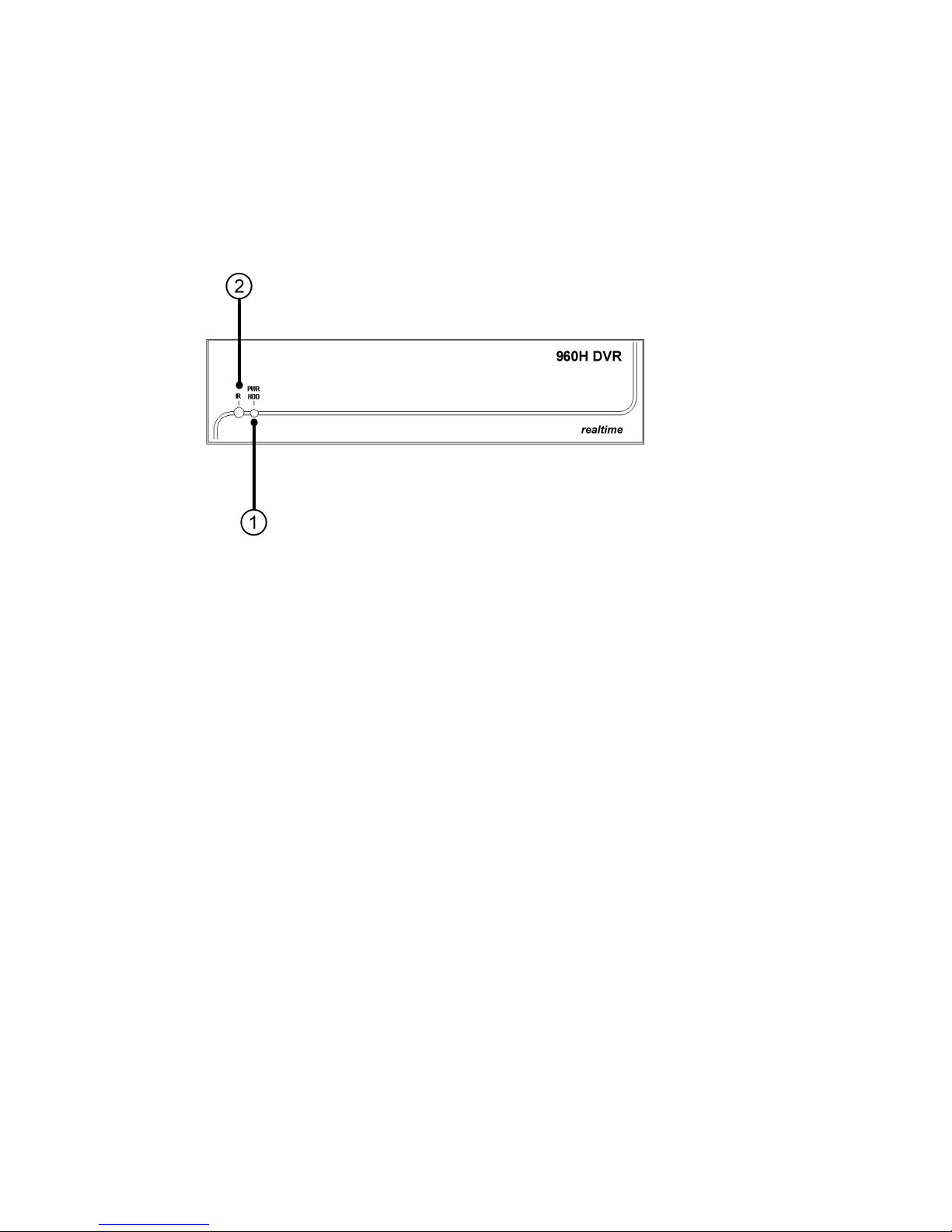
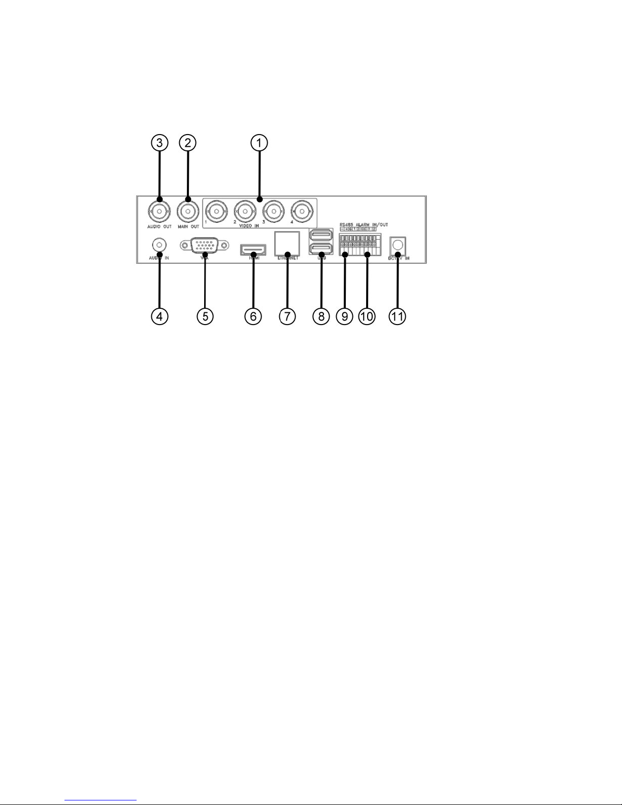
Aposonic A-S0401R21 User manual

- 1
-
Mini 960H/D1 Realtime DVRs
User’s Manual
Models:
4-CH
Before attempting to connect or operate this product,
please read these instructions carefully and save this manual for future use.
SOC3-DVR-Mini-960H-M80795E

- 2
-
CAUTION
TO REDUCE THE RISK OF ELECTRIC SHOCK, DO NOT REMOVE COVER.
NO USER SERVICEABLE PARTS INSIDE.
PLEASE REFER SERVICING TO QUALIFIED SERVICE PERSONNEL.
NOTE: This equipment has been tested and found to comply with the
limits for a Class “A” digital device, pursuant to P
art 15 of the FCC Rules.
These limits are designed to provide reasonable protection against
harmful interference when the equipment is operated in a commercial
environment. This equipment generates, uses and can radiate radio
frequency energy and, if not installed and used in accordance with the
instruction manual, may cause harmful interference to radio
communications. Operation of this equipment in a residential area is
likely to cause harmful interference in which case the users will be
required to correct the interference at their own expense.
FCC Caution: To assure continued compliance, use only shielded
interface cables when connecting to com
puter or peripheral devices.
Any changes or modifications not expressly approved by the party
responsible for compliance could void the user’s authority to operate
this equipment.
This Class A digital apparatus meets all the requirements of the Canadian
Interference Causing Equipment Regulations.
WARNING
TO PREVENT FIRE OR ELECTRIC SHOCK HAZARD, DO NOT EXPOSE THIS
APPLIANCE TO RAIN OR MOISTURE.

- 3
-
LIMITATION OF LIABILITY
THIS PUBLICATION IS PROVIDED “AS IS” WITHOUT WARRANTY OF ANY
KIND, EITHER EXPRESS OR IMPLIED, INCLUDING BUT NOT LIMITED TO,
THE IMPLIED WARRANTIES OF MERCHANTIBILITY, FITNESS FOR ANY
PARTICULAR PURPOSE, OR NON-INFRINGEMENT OF THE THIRD
PARTY’S RIGHT.
THIS PUBLICATION COULD INCLUDE TECHNICAL INACCUACIES OR
TYPOGRAPHICAL ERRORS. CHANGES ARE ADDED TO THE
INFORMATION HEREIN, AT ANY TIME, FOR THE IMPROVEMENTS OF
THIS PUBLICATION AND/OR THE CORRESPONDING PRODUCT(S).
DISCLAIMER OF WARRANTY
IN NO EVENT SHALL THE SUPPLIER BE LIABLBE TO ANY PARTY OR ANY
PERSON, EXCEPT FOR REPLACEMENT OR REASONABLE MAINTENANCE
OF THE PRODUCT, FOR THE CASES, INCLUDING BUT NOT LIMITED TO
THE FOLLOWINGS:
ANY DAMAGE OR LOSS, INCLUDING BUT WITHOUT LIMITATION,
DIRECT OR INDIRECT, SPECIAL, CONSEQUENTIAL OR EXEMPLARY,
ARISING OUT OF OR RELATING TO THE PRODUCT;
PERSONAL INJURY OR ANY DAMAGE CAUSED BY INAPPROPRIATE
USE OR NEGLIGENT OPERATION OF THE USER;
UNAUTHORIZED DISASSEMBLE, REPAIR OR MODIFICATION OF THE
PRODUCT BY THE USER;
ANY PROBLEM, CONSEQUENTIAL INCONVENIENCE, OR LOSS OR
DAMAGE, ARISING OUT OF THE SYSTEM COMBINED WITH THE
DEVICES OF THE THIRD PARTY;
ANY CLAIM OR ACTION FOR DAMAGES, BROUGHT BY ANY PERSON OR
ORGANIZATION BEING A PHOTOGENIC SUBJECT, DUE TO VIOLATION
OF PRIVACY WITH THE RESULT OF THAT SURVEILLANCE-CAMERA’S
PICTURE, INCLUDING SAVED DATA, FOR SOME REASON, BECOMES
PUBLIC OR IS USED FOR THE PURPOSE OTHER THAN SURVEILLANCE.

- 4
-
PRECAUTIONS
Please refer all work related to the installation of this product to
qualified service personnel or system installers.
Do not operate the appliance beyond its specified temperature, humidity
or power source ratings.
Use the appliance at temperature within 0
o
C ~ +40
o
C(32
o
F ~ 122
o
F) and
humidity below 85%.
The input power source for this appliance is +12 VDC.
Performance and lifetime of hard disk drives are easily affected by heat (used
at high temperature). It is recommended to use this appliance at
temperature within +20
o
C ~ +30
o
C(68
o
F ~ 86
o
F)
Handle the hard disk drives with care.
It is possible to damage them if they are moved while their motors are still
running. Do not move them just after turning the power on or off (for around
30 seconds).
Protect the hard disk drives from static electricity.
Do not stack them or keep them upright.
Do not use an electric screwdriver to fix them.
Clean only with dry cloth.
Do not block any ventilation openings.
Do not use the appliance near any heat sources such as radiators, heat
registers, stoves or other apparatus that produce heat.
Protect the power cord from being stepped on or pinched particularly at plugs,
convenient receptacles and the points where they exit from the apparatus.
Do not drop metallic parts through slots. This could permanently damage the
appliance. Turn the power off immediately and contact qualified service
personnel for service.
Handle the appliance with care. Do not strike or shake, as this may damage
the appliance.
Do not expose the appliance to water or moisture, nor try to operate it in wet
areas. Do take immediate action if the appliance becomes wet. Turn the
power off and refer servicing to qualified service personnel. Moisture may
damage the appliance and also cause electric shock.
Do not use strong or abrasive detergents when cleaning the appliance body.
When the dirt is hard to remove, use a mild detergent and wipe gently.
Do not overload outlets and extension cords as this may result in a risk of fire
or electric shock.
Please make a note of your settings and save them. This will help when you
are required to change the system configuration, or when unexpected failure
or trouble occurs.
Distributing, copying, disassembling, reverse compiling, reverse engineering,
and also exporting in violation of export laws of the software provided with this
product, is expressly prohibited.

- 5
-
Table of Contents
1. Product Overview………………….……………………….……...
1.1 Features…………………..…….…………..…………………...
2. Panels And Remote Controller…………...………………….…….
2.1 Front Panel………….……….…………………………….…….
2.2 Back Panel………………….…………………………….……..
2.3 Remote Controller…………..…….……………………….……
3. Installations…….…….……………………………………….……
3.1 Basic Connections…………….………………………….……..
3.2 Optional Connections…………..………………………….……
4. Main ScreenAnd Basic Operations………….……..……….…...
4.1 Text Input……………………………………….………………
4.2 Login And Logout………………………………………………
4.3 Basic Operations…………………………….…………………
4.4 Digital Zoom…….………………………….………….………
5. Menu Display………..……..………………………………….…...
5.1 Status Display….……………………………….………………
5.2 Volume Control…………..……………..……………..………
5.3 Video Adjustment…………..……………..……………..……
5.4 Display……………..…………………..………………………
5.5 Backup Device……………..……………..……………………
5.6 Software Upgrade (Administrator) ……………………………
5.7 System Shutdown (Administrator)……………….……………
6. Setup (Administrator)………………..….………………………...
6.1 Pre-Camera Setup…………………..….………………………...
6.2 Camera Setup……………………………………………………
6.2.1 Video Loss Setup…………………..………………………
6.2.2 Motion Setup……………………….………………………
6.3 Alarm Setup………………….…..…………………….……….
6.4 Main/SEQ Display Setup………………………………………
6.5 Scheduled Record Setup……………..…….………….…………
6.6 HDD Setup………………………………………………………
6.6.1 HDD Format/Clear………………..……………………….
6.6.2 Advanced HDD Setup……………..……………………….
6.7 Password Setup……………………………..…………………..
6.8 System Setup…………...………………………………………
6.9 RS-232/485/IR Setup…………..…………………….………..
6.10 Network Setup……………..…………………………………..
7
7
9
9
10
12
15
15
17
19
20
21
21
23
25
26
27
27
29
30
32
33
34
35
36
39
40
44
47
49
52
54
57
59
63
65
67

- 6 -
6
.
10.1
Notification
Setup
……………..…………
………………..
6.10.2 FTP Setup……………..…………………………………..
6.10.3 3G Modem Setup…………….. .. .. .. ..…………………
6.10.4 Advanced Network Setup……………..…………………
7. PTZ Control……………………….………………………………
8. Search/Playback/Archive (Administrator/Supervisor) ………....
8.1 Search By Time……………………………………….…………
8.2 Search By Event / Log Display………………………….………
8.3 Smart Search………………………..………….……….………
8.4 Search Archived Files………………………….……….………
8.5 Playback/Archive For Search By Time………….….….………
8.6 Playback/Archive For Search By Event…………………………
8.7 Playback/Archive For Smart Search……………………………
8.8 Playback For Archived Files……………………………………
9. Remote Access …………………………………………………..…
9.1 PC Remote Access…………………………………….…………
9.2 PDA/Mobile Phone Remote Access…………………….………
Appendix A – Specifications
Appendix B – Time Zone Table
Appendix C – Keyboard Control Protocol
Appendix D – MS-Windows HEM Utilities
70
71
72
74
76
78
79
81
83
86
87
91
91
92
93
93
102
103
105
107
109

- 7 -
1. Pro uct Overview
The 960H/D1 realtime digital video/audio recorders are designed for use within a
surveillance system with limited space, and are a combination of a hard disk recorder,
a video multiplexer, and a web server. To achieve the highest inter-connectivity and
inter-operability, this series of digital video/audio recorders are all based on
industry-leading front-end to back-end surveillance infrastructure. With
state-of-the-art system architecture, powerful compression/decompression engine, and
intelligent recording algorithms, sixfold operation can be easily achieved without
sacrificing the increasing demands of functionality, performance, reliability, and
availability in the surveillance industry.
1.1 Features
Up to 4 color and/or B/W cameras can be connected
H.264 High Profile video compression/decompression with configurable quality
ADPCM audio compression/decompression
Real sixfold operation - simultaneous record, live, playback, backup, control, &
remote access
Record/playback capabilities –
Full-D1/Half-D1/CIF: up to 120 (NTSC) / 100 (PAL) FPS,
960H: up to 120 (NTSC) / 100 (PAL) FPS.
Realtime live display, 30 (NTSC) / 25 (PAL) IPS, for each channel
Support HDMI output, VGA output, and TV output
Support touch panel with USB interface
Event recording, time-lapse recording or both
Playback search by time or event (alarm, motion, & video loss)
Smart search & playback
Snapshot playback video
Versatile display formats: full-screen & 4 split windows
Digital zoom, X2 & X4
Intelligent motion detection with programmable area and sensitivity
Support privacy mask
Powerful alarm processor with configurable triggering conditions and reactions
Support push alarm notification to mobile phones
One internal 3.5” SATA hard disk drive with storage > 4TB
SupportAdvanced format HDD developed by Western Digital
Video/audio backup to USB2.0 storage devices
Ethernet interface for remote access through web browser or proprietary remote
software, remote alarm notification, FTP video/audio storage, remote setup, and
remote software upgrade
Free DDNS server
Support UPnP
1 I.E./Firefox software for unlimited number of DVRs
PTZ control capabilities & RS-485 keyboard control capabilities
Multi-lingual support
Multi-level password and authentication key protection to ensure high degree of
security

- 8 -
Dynamic streaming video for mobile phone or PDA, no Apps required
Dynamic N-Streaming internet/intranet remote access
Free iPhone/iPad/Android/Mac software app.
Support mouse operation

- 9 -
2. Panels an Remote Controller
2.1 Front Panel
1. LED
Indicators for POWER (LIGHT) and HDD (BLINK).
2. Remote I/R Sensor
Used to receive signal from I/R remote controller.

- 10 -
2.2 Back Panel
1. Video Input Connectors (1-4)
Connect system cameras to these BNC connectors. The internal 75Ω
termination is always ON.
2. Main Out (MAIN OUT)
Connect TV monitor to the BNC connector for main/call monitor display.
3. Audio Output Connector (AUDIO OUT)
The connector supplies line-out audio signal to external devices such as
speakers. Recorded audio will be supplied from AUDIO OUT during
playback.
4. Audio Input Connector (AUDIO IN)
The RCA connectors accepts line-in audio signal supplied from external
devices such as microphone amplifiers.
5. VGA Connector (VGA)
Connect VGA monitor to the optional D-SUB 15-pin female connector for
main monitor display.
6. HDMI Connector
Connect HDMI monitor to the HDMI connector for main monitor display.
7. Ethernet Connector
Connect this unit to a 10/100Base-T Ethernet network through this port.
8. USB2.0 Connectors (USB)
Connect one of the USB 2.0 connectors to USB mouse. Connect the

- 11 -
other USB 2.0 connector to USB 2.0 compatible device, such as USB 2.0
disk drive, DVD+RW, USB 3G dongle, etc.
9. RS-485 Connector (Optional)
Connect this connector to RS-485 compatible PTZ camera(s) or keyboard.
Please refer to the manuals come with the RS-485 compatible devices for
the correct settings. Please refer to Appendix C for the Keyboard Control
Protocol for the digital video recorder.
10.Alarm Input/Output Connectors (ALARM IN 1-2, ALARM OUT
NC(1)/NO(2), Optional)
Connect the input connectors to external devices such as sensors or door
switches, and connect NC connector (left) to Normally Closed (NC) alarm
output, or NO connector (right) to Normally Open (NO) alarm output.
Please note that only one of the NC or NO connectors can be
connected only.
11.Power Cord Inlet (DC 12V)
Connect to DC +12V power source.

- 12 -
2.3 Remote Controller
The remote controller is an optional accessory to ease the user’s operations. You can
do all the operations by the remote controller instead of the buttons on the front panel.
The effective distance is about 10 meters without any obstacle.
The descriptions of the buttons are as below:
1. DVR ID Selection Buttons (DVR #1-4)
Press these buttons to select the DVR to be controlled by the remote
controller. The remote controller can control up to 4 sets of DVRs.
Please make sure that the DVR ID (in IR Setup) for each of the DVRs is
set correctly.
2. Alpha-numeric Buttons (1-9, 0, *, #)
Press these buttons for camera selection in most of the circumstances.
These buttons can also be used to enter text and number in the way
similar to most of the mobile phones.
3. Alarm Reset Button
Press this button to cancel alarm activation, and return the system to the
condition before the alarm was activated.
4. REC Button
Press this button to force manual recording. To stop manual recording,
press it again.
5. MUTE/NEXT Button
Press this button to mute the audio.
6. X2/GOTO Button
In full screen display, press this button for Digital Zoom (X2/X4).
7. MENU / ESC Button
Press this button to display the main menu or escape to the upper level
display.

- 13 -
8. Up/BS Button (▲/BS)
Press this button to move the cursor or focus window in most
circumstances. In text editing mode, this button is used as “backspace”
key.
9. Down/DEL Button (▼/DEL)
Press this button to move the cursor or focus window in most
circumstances. In text editing mode, this button is used as “del” key.
10.Left/Right Buttons (◄,►)
Press these buttons to move the cursor or focus window.
11.ENTER Button
This button is used as “enter” key.
12.(Split Windows) +/- Buttons ( )
In split-window display, press these buttons for next/previous split-window
display. In the others, press these buttons to change the contents.
13. (Vol/Zoom) +/- Buttons ( / / )
Press these buttons to change the volume.
14.MODE Button
Press this button to toggle between live mode and playback mode in main
screen display. In some dialogs, this button is used as a miscellaneous
function key. At playing, this button is used as “slow backward”.
15.SEQ Button
Press this button to switch to or return from SEQ display mode in main
screen display. In some dialogs, this button is used as a miscellaneous
function key. At playing, this button is used as “slow forward”.
16.CALL Button
Press this button to switch to or return from full screen display of the focus
camera in main screen display. In some dialogs, this button is used as a
miscellaneous function key.
17.SEARCH Button
Press this button to display the search menu in main screen display. In
some dialogs, this button is used as a miscellaneous function key.
18.Fast Backward Button ( )
Press this button for fast backward playback.
19.Fast Forward Button ( )

- 14 -
Press this button for fast forward playback.
20.Single Step Button ( )
Press this button to play the recorded images frame by frame.
21.Copy Button ( )
Press this button to copy the playback images to the storage device
connected to the USB port. Press this button again to stop copying.
22.Play/Pause Button ( )
Press this button to play the recorded images, or pause the playback.
23.Stop Button ( )
Press this button to stop the playback.

- 15 -
3. Installations
The installations described below should be made by qualified service personnel or
system installers.
3.1 Basic Connections
Please refer to the following diagram for the connections.
Please make sure to set the NTSC/PAL Selector Switch on the main board
according to the local TV system for the system to work correctly.
Cameras
Connect the camera video input connectors to the video outputs from system
cameras or other composite video sources via coaxial cables. The internal 75Ω
termination is always ON.
Main monitor
Connect the main monitor output connector (BNC/VGA/HDMI) to a surveillance
TV/VGA monitor. The TV/VGA monitor displays selected live or recorded
cameras in any available split window format.
Hard disk drive
Make sure to install one SATA hard disk (Max. storage size >3TB) inside the
DVR. The steps are as below:

- 16 -
1. Power off the machine, and then
use a screwdriver to uncover it.
2. Connect the cables as shown.
3. Hold the SATA HDD, and use a
screwdriver to fix it as shown.
4. Cover the machine.
Note 1: The HDD must be formatted before it can be used to record
video/audio. Please refer to Section 6.6.1 to format the HDD.
Power
Connect DC 12V power source to DC 12V.

- 17 -
3.2 Optional Connections
Audio input
Connect the audio input connector to the audio line-out from system camera or
other audio sources. Please make sure to associate the audio input with the
camera in Camera Setup as described in Section 6.2 accordingly.
Audio output
Connect the audio output connector to the audio line-in from speakers.
Alarm input (Optional)
Connect the alarm inputs to NC and/or NO type of alarm signals. Please make
sure to setup the alarm configurations as described in Section 6.3 accordingly.
Alarm output (Optional)
Connect the alarm output #1 to NC type of alarm signal, or alarm output #2 to NO
type of alarm signal.
Ethernet
Connect the Ethernet connector to a standard twisted-pair Ethernet cable for
remote access via LAN or internet. Please make sure to setup the related
configurations as described in Section 6.10 Network Setup.
USB 2.0 disk drives, DVD+RW, card reader, etc.
If the user wants to use USB2.0 peripheral device to retrieve important recorded
images and/or audio, please connect it to the USB2.0 port connector.

- 18 -
I/R remote controller
The user may use I/R remote controller to control the digital video/audio recorder.
Call monitor
Connect the main monitor output connector to a surveillance TV monitor. This
monitor can be set to displays the full screen images of the cameras associated
with the events (alarm or motion) or the images from the installed cameras
sequentially according to the SEQ Display Setup (Section 6.4) for call monitor.
PTZ Cameras (Optional)
Connect the RS-485 connector to PTZ camera(s) via the appropriate cable. The
system supports a variety of different PTZ cameras, including Pelco D protocol
Dome, SamSung SCC-641P, Kalatel Cyber Dome, Bosch AutoDome, etc. But
different PTZ cameras can coexist in a system only if they support the same
protocol. Please make sure to set the PTZ ID of the camera(s), and setup the
camera (Section 6.1), and RS-422/485 (Section 6.9) accordingly.
RS-485 keyboard or Terminal (Optional)
Connect the RS-485 connector to a RS-485 keyboard controller or VT-100
terminal via the appropriate cables. Please refer to the diagram above for the
correct connection. Please make sure to setup the RS-422/485 configurations as
described in Section 6.9 accordingly. Please refer to Appendix C for the
Keyboard Control Protocol for the digital video recorder.

- 19 -
4. Main Screen An Basic Operations
The split-window screen, as shown above, is the main screen after system startup.
There are two types of split-window screens, including 1-Window and 4-Window.
The system will remember the last one before normal shutdown (as described in
Section 5.7) of the system. In addition to the split windows, the system time is
displayed on the lower-left corner, the system states on the lower-right corner, and the
rolling screen messages, if shown while certain event occurs, on the lower corner.
The system states, from right to left, are described as the followings:
(1) Normal recording percentage,
(2) Alarm recording percentage,
(3) X2 state – X1, X2, or X4,
(4) Manual record ON/OFF – REC shown for ON,
(5) Backup state – Backup icon shown for backup, and
(6) SEQ display ON/OFF or playback state – SEQ icon shown for SEQ display ON,
other icons for different playback states.
* If mouse is connected, the mouse operation icons will be shown when the mouse
cursor is moved to the bottom of the screen.
* Recording icon, Motion, & Alarm for the camera may be shown after camera title.

- 20 -
4.1 Text Input
There are certain circumstances that the system requires the user to enter text, such as
system login, camera title setup, and so on. Please follow the steps below to enter
text:
(1) Press ENTER to edit the highlighted option. The flashing cursor will be shown
to indicate the editing point.
(2) Press ◄► to move the cursor to the left/right.
(3) Press code in text editing mode to change text case. (If this entry can accept
number only, pressing code will have no effects.) Indicators on the screen show
the current setting:
123 = Number only
abc = No capital letters
ABC = All capital letters
CODE = Internal code for the selected language, such as Chinese, Japanese, etc.
(4) Press a number key (1-9, 0) repeatedly until the character you want appears (1for
1 or space, 2for 2, a/A, b/B, or c/C, etc.). If internal CODE is selected, a
CODE box will be shown (after the first code is entered) for each new code to be
entered. Please check the internal code table for the selected language. For
2-byte code, e.g. Chinese or Japanese, the code accepted is from 0000 - FFFF.
(5) Press mark to bring up a list of punctuation marks and special characters. The
highlighted character in the list shows the selected one. Press ▲▼◄► to
change the selection.
(6) If you make a mistake, press BS to remove the character to the left of the cursor,
or press DEL to delete the character at the current cursor position.
(7) In text editing mode, internal code box, and mark list, press ENTER to exit and
save changes, press ESC to exit without making changes.
Note: If the user clicks on the left button of the mouse on the item, a Keyboard
Simulator will be shown. Click on ‘#’ (or “abc”, ..) to change text case.
Click on the alpha-numeric characters to enter text (or CODE). Click on ‘*’
for mark.
Table of contents
Other Aposonic DVR manuals