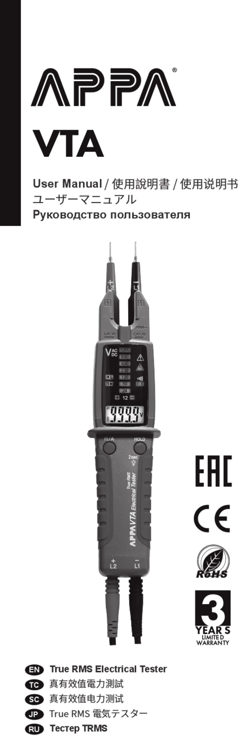
APPA VP-2 User manual

VP-2
User Manual / 使用說明書 / 使用说明书
ユーザーマニュアル
Руководство пользователя
Voltage Tester
電壓測試儀
电压测试仪
電圧テスター
Индикатор опасного напряжения
RU
EN
TC
SC
JP
LIMITE D
WARRAN TY
YEAR S

VP-2 EN
Read First
Safety Information
WARNING
Understand and follow operating instructions
carefully. Use the meter only as specied
in this manual; otherwise, the protection
provided by the meter may be impaired.
• Only touch the instrument handle for any
detection. Do not touch the tip of the
instrument while testing. When using
detector, keep your ngers behind thenger
guards.
• Use the detector only as specied in this
manual or the protection by the detector
might be impaired
• Before use, check the instrument for
damages. Do not use the tester if damages
are detected.
• Use caution with voltages above 30 Vac
rms, 42 Vac peak,or 60 Vdc. These voltages
pose a shock hazard.
• The signal during the voltage detection does
not provide any indication of the type and
level of voltage present. when testing mains
connected cables for interruptions the user
must ensure that both lines are connected
once to phase.
• Do not use detector around explosive gas or
vapor.
• To reduce the risk of re or electric shock do
not expose this product to rain or moisture.
• The detector must only be used under
conditions and for the purposes for which it
has been designed. Particular attention
should be paid to the safety instructions,
the technical specications relating to
environmental conditions and the use of the
detector in dry surroundings.
1

VP-2 EN
WARNING
CAUTION
Identies hazardous conditions and actions
that could cause BODILY HARM or DEATH.
Identies conditions and actions that could
DAMAGE the detector or equipment under
test.
Symbols as marked on the
Meter and Instruction manual
See instruction manual
Equipment protected by double or reinforced insulation
Battery
Conforms to EU directives Conforms to EU
Do not discard this product or throw away
• The following factors might aect the correct
functioning of the phase test and phase
sequence test :
- excessive distance to the phase (external
conductor) to be tested
- excessive insulation and shielding of the
phase (external conductor)
- protective clothing and insulating
conditions on site
- constructional dierences of sockets / CEE
couplings with recessed contacts, e.g. 63
A CEE coupling
- mains failures or lacking mains quality
- battery condition
2

VP-2 EN
The Meter Description
Features
• AC Voltage detection on conductive and
insulated parts.
• Phase sequence indication and conformity
phase test.
• Test on outlets, cables and /or electrical
appliances.
• Visible LED and acoustic buzzer indications.
• Practical pen clip and very small size.
• Auto Power OFF.
• Meter suitable for any electrical installer.
Compact design with convenient battery
door.
• CAT. IV 600V /CAT. III 1000V Safety
Standard.
1. Test probe.
2. Detection result Indication area.
(Red light/Green light)
3. Clip.
4. Battery cover.
5. Function key.
6. Phase sequence detection mode indication.
(Red light / Green light)
7. Voltage detection mode indication.
(Yellow light)
4
3
1
2
7
5
6
7
6
5
3

VP-2 EN
Switch detection mode
Voltage detection
Press function key to switch Voltage/Phase
detection mode.
On AC Voltage detection mode: the Yellow
light of this mode ashing.
Phase rotation detection mode: the Red light
of this mode ashing.
While detecting the voltage >100Vac of the
conductor, the Yellow light of this mode is
still on and the Red light in the Detection
result indication area is ashing with beeping
intermittently.
The higher voltage with quicker intermittency
Click
Voltage test at insulated conductors.
Power On/O
Auto Power O
Press function key for 1 seconds to turn the
VP2 on/o.
The detectors will automatically power o
after approximately idle 5 minutes.
4

VP-2 EN
Phase sequence indication
1. Test on 1st line, the Red light of this mode
is ashing once/sec with beeping, keep the
test on L1 until the Green light of this mode
is stiil on.
2. Move the probe tip to 2nd line in 2
seconds, test on 2nd line the Green light of
this mode turns to ashing once/sec from
still on with beeping.
3. When test is completed the Green light of
this mode is O and the test result is
shown on detection result indication area
as mentioned in Phase sequence
indications.
Locating line interruptions.
Red light flashing
with Beeping
1
2
3
Line 3
Line 2
Line 1
5

VP-2 EN
Phase sequence indications
Note:
Battery replacement
The test result is to be one of light showings
below with 3 intermittent beeps in 5 seconds.
1.1st line ahead 2nd line: The Green light of
Detection result indication area is still on.
(1st line >> 2nd line)
2.1st line after 2nd line: The Red light in
Detection result indication is still on.(2nd
line >> 1st line)
3.The same phase eld indication :
The Green Light in Detection result
indication is ashing.
4.Error indication : The Green light and Red
light in Detection result indication are
ashing alternately. Detection result
represented the relation of Line 1 and
Line2 and Line3(Left rotary / Left rotary).
5.The phase sequence test always requires
a countercheck during which the phase
sequence must change.
Always hold the device steady during the
measurements without wobbling.
Mains failures or a lacking mains quality might
aect the correct functioning of the device.
Unscrew the battery cover Remove
discharged batteries and insert new by
respecting the correct polarity. Close the
battery cover careful.
6

VP-2 EN
Maintenance
Cleaning
Do not attempt to repair this Detector. It
contains no user-serviceable parts. Repair
or servicing should only be performed by
qualied personnel.
Periodically wipe the case with a dry cloth
and detergent.
Do not use abrasives or solvents.
If the instrument is likely to remain unused
for a long period it is advised to remove the
batteries. Please think of our environment
when getting rid of used batteries. They
should be disposed in a place suitable for
hazardous waste.
WARNING
7

VP-2 EN
Specications
Auto Power O : Approx 5 minutes
Voltage range : 100VAC~1000 VAC
Frequency : 45 ~ 65 Hz
Overvoltage category :
Designed to meet IEC 61010 & UL61010
CAT III 1000 VAC, CAT IV 600 VAC
CAT Application eld
I The circuits not connected to mains.
II The circuits directly connected to Low-
voltage installation.
III The building installation.
IV The source of the Low-voltage
installation.
Protection category : IP 53
Battery Life : 150 hours (standby)
Pollution Degree: 2
Operating temperature :
-10 °C ~ 50 °C
-10 °C ~ 40 °C (≤ 75% RH)
40 °C ~ 50 °C (≤ 45% RH)
Storage temperature : -20 to 60 °C for
current, 0 to 80% RH (batteries not tted).
Power supply : 2x AAA, 1.5 V LR03
Dimensions :
20.6mm(W) x 151mm(L) x 25.2mm(D)
Weight : approx. 40 g (incl. batteries)
Drop Protection : 4 feet drop to hardwood on
concrete oor.
8

VP-2 EN
Limited Warranty
The testers are subject to stringent quality
controls. If in the course of normal daily
use a fault should occur, we provide 3 year
guarantee (only valid with invoice) .
Faults in manufacture and materials will be
rectied by us free of charge, provided the
tester has not been tampered with, and is
returned to us unopened.
Damage due to dropping, abuse ormisuse is
not covered.
Our service department will promptly repair
any fault that occur outside the guarantee
period.
This instruction manual has been prepared
with great care.
No liability is accepted for the correctness
and completeness of the data and illustra-
tions it contains.We reserve the right to make
technical alterations.
9

VP-2 TC
請先瀏覽
安全資訊
警告
請詳閱並按照操作說明操作。僅依此手冊指定
之用法使用偵測儀,否則電錶提供之保護可能
失效。
•在偵測時,僅能碰觸儀器手把。測試時請勿
碰觸儀器尖端。當使用偵測儀時,將手指置
於手指護套後方。
•僅依此手冊指定之用法使用偵測儀,否則偵
測儀提供之保護可能失效。
•使用前請先確認儀器是否有損壞。若有發現
損壞,請勿使用。
•當電壓大於 30 伏特交流電有效值、42 伏特
交流電高峰或 60 伏特直流電時,請小心使
用。這些電壓值有觸電危害。
•電壓偵測時所發出的訊號,不表示任何存在
電壓的形式或大小。
當測試主開關連接纜線有無干擾時,使用者
須確認兩條線有一起連接至相位。
•請勿於爆炸性氣體或蒸氣環境下使用偵測儀。
•為降低火災及觸電風險,請勿將此產品暴露
於雨水或潮濕環境下。
•偵測儀僅能於其設計使用之狀況及目的下操
作。需特別注意安全說明、與環境狀況相關
之技術規格,並於乾燥環境下使用偵測儀。
•下列因素可能會影響相位測試及相位順序測
試的正確執行:
- 與待測相位(外部導體)距離過遠
- 相位(外部導體)有過多絕緣及屏蔽
- 環境有保護布料及絕緣狀態
- 插座 /CEE 連接有凹槽接觸之結構性差異,
例如 63 A CEE 連接
- 主開關故障或主開關品質不良
- 電池狀態
10

VP-2 TC
警告
注意
特色
偵測儀及說明卡上標示之圖示
注意可能導致傷害或死亡之危害狀況及動作。
注意可能導致偵測儀或待測設備毀損之狀況及
動作。
• 導電及絕緣零件上交流電壓偵測。
• 相位順序指示及相位一致性測試。
• 測試插座、纜線及 / 或電子設備。
• 可見的 LED 及可聽見的嗶聲指示。
• 典型筆夾且尺寸極小。
• 自動關機。
•電錶適用於任何電子設備。有便利的電池蓋
之相容性設計。
• CAT. IV 600 伏特 /CAT. III 1000 伏特安全標
準。
請參閱說明手冊
設備有雙層或加強絕緣
電池
符合歐盟規定
請勿任意丟棄此產品
11

VP-2 TC
電錶描述
開機 / 關機
自動關機
按壓功能鍵一秒,即可將 VP2 開機 / 關機。
閒置約五分鐘後,偵測儀會自動關機。
1. 測試探針。
2. 偵測結果指示區域。 (紅燈 / 綠燈)
3. 夾子
4. 電池蓋
5. 功能鍵
6. 相位順序偵測模式指示。 (紅燈 / 綠燈)
7. 電壓偵測模式指示。 (黃燈)
4
3
1
2
7
5
6
7
6
5
12

VP-2 TC
切換偵測模式
點擊
按壓功能鍵,以切換電壓 / 相位偵測模式。
於交流電壓偵測模式:此模式之黃燈閃爍。
相位旋轉偵測模式:此模式之紅燈閃爍。
電壓偵測
當偵測導體電壓大於 100 伏特交流電時,此模
式之黃燈會持續亮起,且偵測結果指示區域之
紅燈會閃爍並伴隨間歇性嗶聲。
電壓越高,嗶聲間隔越短。
絕緣導體電壓測試
13

VP-2 TC
1
2
3
相位順序指示
1. 測試第一條線,此模式之紅燈會每秒閃爍一
次並伴隨嗶聲,持續測試 L1,直到此模式綠
燈恆亮。
2. 兩秒內移動探針尖端至第二條線,測試第二
條線此模式之綠燈,會從恆亮有嗶聲,變成
每秒閃爍一次。
3. 當測試完成時,此模式之綠燈關閉且測試結
果顯示於相位順序指示中提到過的偵測結果
指示區。
紅燈閃爍且嗶聲響
線1
定位線路障礙
線2
線3
14

VP-2 TC
警告
相位顺序指示
備註:
更換電池
測試結果會顯示下方燈號之一,並伴隨五秒內
3 次間歇性嗶聲。
1. 第一條線在第二條線之前:偵測結果指示區
綠燈恆亮。 (第一條線 >> 第二條線)
2. 第一條線在第二條線之後:偵測結果指示區
紅燈恆亮。 (第二條線 >> 第一條線)
3. 相同相位場指示:偵測結果指示區綠燈閃
爍。
4. 錯誤指示:偵測結果指示區的綠燈與紅燈交
替閃爍。
偵測結果展示線 1、線2 及線 3 之關聯性(左
旋 / 右旋)。
5. 相位順序測試於相位順序改變時,需要反向
確認。
在量測時,請務必穩定握住儀器,不要搖晃。
主開關故障或品質不良,會影響儀器正確執
行。
鬆開電池蓋,移除放電完之電池,並依正確極
性放入新的電池。請小心關上電池蓋。
若儀器可能長時間不會使用,建議移除電池。
在丟棄使用過的電池前,請先考慮我們的環
境。使用過後的電池需,丟棄於合適之危害廢
棄物棄置處。
15

VP-2 TC
保養
清潔
規格
請勿試圖維修此偵測儀,其包含無使用者服務
之零件。維修或服務僅能由合格認證人員執
行。
自動關機:約五分鐘
電壓範圍:100 伏特交流電 ~1000 伏特交流電
頻率:45~65 赫茲
過電壓分類:設計符合 IEC 61010 及 UL
61010 CAT III 1000 伏特交流電、CAT IV 600
伏特交流電
CAT 應用領域
I 電路無連接至主開關。
II 電路直接連接至低電壓設備。
III 建築設備。
IV 低電壓設備電力來源。
保護分類:IP 53
電池壽命:150 小時(待機狀態)
污染程度:2
操作溫度:
-10℃ ~50℃
-10℃ ~40℃(小於等於 75% 相對濕度)
40℃ ~50℃(小於等於 45% 相對濕度)
儲存溫度:針對電流為 -20 至 60℃,0 至
80% 相對濕度(電池移除)
電力供應:兩個 AAA 1.5 伏特 LR03 電池
尺寸:20.6 毫米(寬)x 151 毫米(長)x
25.2 毫米(深)
重量:約 40 克(含電池)
墜落防護:4 呎掉落至水泥地上硬木。
請定期以乾布及清潔劑擦拭外殼。
請勿使用磨料及溶劑。
16

VP-2 TC
有限保固
此測試儀通過嚴格之品質管控。若正常日常操
作下故障發生,本公司提供 3 年保固(必須隨
附發票才有效)。
對於製造與材料方面的缺陷,本公司將提供免
費修復,但前提為該測試儀並未被蓄意竄改,
並且在未開封的情況下寄回給我們。
本保固不包含因墜落、濫用或錯誤使用導致之
毀損。
對於保固期外發生的故障,本公司服務部門將
即時修復。
此說明手冊經過審慎編寫。
對於其中數據之正確性與完整性以及圖示,不
承擔任何責任。
本公司保有進行技術更動之權利。
17

VP-2 SC
请先阅览
安全资讯
警告
请详阅并按照操作说明操作。仅依此手册指定
之用法使用侦测仪,否则电表提供之保护可能
失效。
•在侦测时,仅能碰触仪器手把。测试时请勿
碰触仪器尖端。当使用侦测仪时,将手指置
于手指护套后方。
•仅依此手册指定之用法使用侦测仪,否则侦
测仪提供之保护可能失效。
•使用前请先确认仪器是否有损坏。若有发现
损坏,请勿使用。
•当电压大于 30 伏特交流电有效值、42 伏特
交流电高峰或 60 伏特直流电时,请小心使
用。这些电压值有触电危害。
•电压侦测时所发出的讯号,不表示任何存在
电压的形式或大小。
当测试主开关连接缆线有无干扰时,使用者
须确认两条线有一起连接至相位。
•请勿于爆炸性气体或蒸气环境下使用侦测仪。
•为降低火灾及触电风险,请勿将此产品暴露
于雨水或潮湿环境下。
•侦测仪仅能于其设计使用之状况及目的下操
作。需特别注意安全说明、与环境状况相关
之技术规格,并于干燥环境下使用侦测仪。
•下列因素可能会影响相位测试及相位顺序测
试的正确执行:
- 与待测相位(外部导体)距离过远
- 相位(外部导体)有过多绝缘及屏蔽
- 环境有保护布料及绝缘状态
- 插座 /CEE 连接有凹槽接触之结构性差异,
例如 63 A CEE 连接
- 主开关故障或主开关品质不良
- 电池状态
18

VP-2 SC
警告
注意
特色
侦测仪及说明卡上标示之图示
注意可能导致伤害或死亡之危害状况及动作。
注意可能导致侦测仪或待测设备毁损之状况及
动作。
• 导电及绝缘零件上交流电压侦测。
• 相位顺序指示及相位一致性测试。
• 测试插座、缆线及 / 或电子设备。
• 可见的 LED 及可听见的哔声指示。
• 典型笔夹且尺寸极小。
• 自动关机。
• 电表适用于任何电子设备。有便利的电池盖
之相容性设计。
• CAT. IV 600 伏特 /CAT. III 1000 伏特安全标
准。
请参阅说明手册
设备有双层或加强绝缘
电池
符合欧盟规定
请勿任意丢弃此产品
19
Table of contents
Languages:
Other APPA Test Equipment manuals