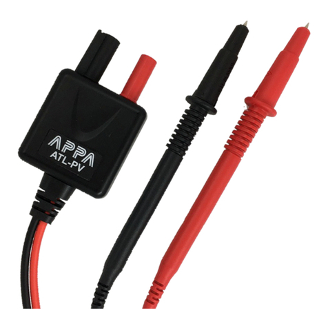
APPA VTA User manual

VTA
User Manual / 使用說明書 / 使用说明书
ユーザーマニュアル
Руководство пользователя
LIMITE D
WARRAN TY
YEAR S
EN True RMS Electrical Tester
真有效值電力測試
真有效值电力测试
True RMS 電気テスター
Тестер TRMS
TC
SC
JP
RU

VTA EN
Read First
Safety Information
WARNING
Understand and follow operating instructions
carefully.
• If the equipment is used in a manner not specied
by the manufacturer, the protection provided by the
equipment may be impaired.
• Always use proper terminals, switch position, and
range for measurements.
• To reduce the risk of re or electric shock, do not
use this product around explosive gas or in damp
locations.
• Verify the Meter operation by measuring a known
voltage. If in doubt, have the Meter serviced.
• Do not apply more than the rated voltage, as
marked on Meter, between terminals or between
any terminal and earth ground.
• Avoid working alone so assistance can be rendered.
• Do not use the Tester if the Tester is not operating
properly or if it is wet.
• Individual protective device must be used if
hazardous live parts in the installation where the
measurement is to
be carried out could be accessible.
• Use caution with voltages above 30 Vac rms, 42
Vac peak, or 60 Vdc. These voltages pose a shock
hazard.
• DO NOT USE the test leads when the internal white
insulation layer is exposed.
• DO NOT USE the test leads above maximum
ratings of CAT. environment, voltage and current,
that are indicated on the probe and the probe tip
guard cap.
• DO NOT USE the test leads without the probe tip
guard cap in CAT III and CAT IV environments.
• Probe assemblies to be used for MAINS
measurements shall be RATED as appropriate for
MEASUREMENT CATEGORY III or IV according to
IEC 61010-031 and shall have a voltage RATING of
at least the voltage of the circuit to be measured.
• Disconnect circuit power and discharge all high-
voltage capacitors before testing resistance,
continuity.
1

VTA EN
Symbols as marked on the
Meter and Instruction manual
Risk of electric shock
See instruction manual
DC measurement
AC measurement
Both direct and alternating current
Equipment protected by double or reinforced insulation
Battery
Earth
Conforms to EU directives
Application around and removal from hazardous
live conductors is permitted
Do not discard this product or throw away.
Do not attempt to repair this Meter. It contains no
user serviceable parts. Repair or servicing should
only be performed by qualied personnel.
Periodically wipe the case with a dry cloth and
detergent.
Do not use abrasives or solvents.
Preparation and Caution Before Measurement
Observe the rules of Warnings and Cautions.
Maintenance
Cleaning
Making Basic Measurements
CAUTION
• When connecting the test leads to the DUT (Device
Under Test) connect the common test leads before
connecting the live test leads ; when removing the
test leads, remove the live test leads before
removing the common test leads.
• Make sure that the buzzer sound is perceptible
before using it under high background noise
environment.
2

VTA EN
Voltage Measurement
LED indicates measured voltage is high than ELV
limit (50VAC and/or 120VDC).
Warning
• When batteries are not tted or are exhausted, the
tester still work when measuring> 45VAC and/or
>35VDC.
• Timing Rating (tr): 30 seconds, Recovery Time (rt):
240seconds,when measuring >300V, recovery time
is necessary.
• L/R LED may light up when measuring AC voltage.
• Due to the high internal resistance, capacitive and
inductive Voltage (ghost voltage) may be indicated.
Voltage/Continuity/Single Pole Mode
+DC
-DC
AC
3

VTA EN
- Clockwise Phase Sequence L1-L2-L3(Right)
- Counterclockwise Phase Sequence L1-L3-L2(Left)
Phase Rotation Test
4

VTA EN
Single Pole Phase Check
Warning
Warning
Note
Phase Rotation Test works only on 3 phase 4 wire
system. The result is unreliable on other systems.
It is necessary to check the result by test with reverse
sequence.
• Single Pole Check is available for both test leads.
Remove one of test leads before performing check.
• Do not check if voltage appears by Single Pole
Phase Check. Measure voltage with two pole to get
a reliable result.
5

VTA EN
Continuity Check
Resistor Mode
6

VTA EN
Ampere Mode
Warning
Warning
The barrier on the body is indicating the limit of safe
access of the hand-held part, do not hold over the
barrier when in normal use.
Do not assemble test lead at the back of the meter
while measuring current.
7

VTA EN
HOLD
Press Ω/A button and “HOLD” button at the same time.
Using the Function
Enable/Disable ELV Warning Voice
Turn the meter OFF
Voltage/Continuity/Single Pole Mode Voltage/Continuity/Single Pole Mode
8

VTA EN
Torch
Self-Diagnostic Test
Powering ON
Press >2sec.
Warning
Do not use the tester when abnormality is found in
self-diagnostic test.
OFF
Press
or
9

VTA EN
Function Button
Battery Replacement
Warning
• To avoid false readings that can lead to electric
shock and injury, replace the battery as soon as low
battery indicator blinks.
• Remove test lead from Meter before opening the
battery door or Meter case.
PRESS BUTTON
Ampere MODE
PRESS BUTTON
Resistor MODE
PRESS BUTTON
over 2sec.
Voltage/Continuity/Single Pole
MODE
-
unscrew
unscrew
+
1.5V AAA x 2 -
10

VTA EN
Probe Usage
Warning
Warning
• For CAT III or CAT IV environments, use the test
leads with the probe tip guard cap xed rmly.
Without the probe tip guard cap, the test leads can
be used in CAT II environment ONLY.
• Make sure test leads are rmly connected to
instrument and other accessories.
When using test leads or
probes,keep your ngers
behind the nger guards.
Finger Guard
Tighten
unscrew
11

VTA EN
Test lead assembly
Storage
Warning
Do not assemble test lead
at the back of the meter
while measuring current.
For 19mm power socket
For most application except
ampere measurement.
12

VTA EN
Specications
1-1 General Specications
1-2 Environmental Conditions
Display Count : 10000 counts.
Overrange Display : ”OL” or “-OL”
Conversion Rate : 3 times/second
Dimensions (W x H x D) : 57 x 220 x 35 mm
Weight : 200g
Power Requirements :
AAA Size Batteryx2(R03, LR03, 24D, 24A)
Battery Life : About 1000 operations. (based on
Alkaline
batteries, 30 sec. ON, 240 sec. OFF)
Maximum Conductor Size : 16mm
Safety Standard Compliance :
IEC / EN 61010-1, IEC / EN 61010-2-032,
IEC / EN 61010-2-033,
IEC / EN 61010-031 for CAT IV 600V, CATIII 1000V
IEC / EN 61326-1 IEC / EN 61243-3
Indoor / Outdoor Use
Pollution Degree : 2
Maximum Operating Altitude : 2000m (6562ft)
Operating Temperature & Relative Humidity :
-15°C ~ 30°C, ≤ 80%RH
30°C ~ 40°C, ≤ 75%RH
40°C ~ 55°C, ≤ 45%RH
Storage Temperature : -20 to +60°C, 0 to 80% RH
(no batteries)
Temperature Coecient :
0.2 x (Specied accuracy) / °C, < 18°C, > 28°C
IP Rating : IP65
Vibration :
Random Vibration per MIL-PRF-28800F Class 2
Drop Protection :
4 feet drop to hardwood on concrete oor
CAT Application eld
I
II
III
The circuits directly connected to Low-voltage
installation.
The building installation.
The source of the Low-voltage installation.
13

VTA EN
1-3 Electrical Specications
Accuracy is given as ± (% of reading + counts of least
signicant digit) at 23°C ± 5°C, with relative humidity
Less than 80% R.H., and is specied for 1 year after
calibration.
• Condition of Auto Power On :
With batteries tted :
- > 3.0V or < -8.0V between L2 and L1
- Detect AC signal by Single Pole
- Continuity
Without batteries :
> | ±35.0V DC | or > 45.0V AC between L2 and L1
• Auto Power O :
The Meter automatically turns o if one of the
following conditions are met for about 10 seconds
- The Auto Power On condition is not met.
- Both buttons are not pressed.
The Meter automatically turns o if one of the
following conditions are met for about 30 seconds
- The resistance is OL when the Meter is in Resistor
mode.
- The current is < 1.0A when the Meter is in Ampere
mode
• For > 300V, Time rating (tr): 30 seconds;
Recovery time (rt): 240 seconds
• AC Function
- ACV and ACA specications are ac coupled, true
RMS.
- For non-sinusoidal waveforms, Additional Accuracy
by Crest Factor (C.F.) :
Add 1.0% for C.F. 1.0 ~ 2.0
Add 2.5% for C.F. 2.0 ~ 2.5
Add 4.0% for C.F. 2.5 ~ 3.0
- Max. Crest Factor of Input Signal:
3.0 @ 5000 counts
1.5 @ 10000 counts
14

VTA EN
• DC Voltage
• AC Voltage
• Resistor
• Continuity
With
batteries
With
batteries
9999Ω
7.0V to 999.9V
6.0V(1) to
999.9V
1Ω
0.1V
0.1V
Without
batteries(1)
Without
batteries(1)
50.00kΩ
35V to 999.9V
45V to 999.9V
0.01kΩ
0.1V
0.1V
±(1.0% +
2D)
±(1.5% +
5D)
±(1.5% + 5D)
Range
Range
Range
Resolution
Resolution
Resolution
Accuracy
Accuracy
Accuracy
(1) Measurement without batteries is only available
for < 35°C,> -15°C. The meter will show “bAtt” and
ELV LED when measurement is not available.
Max. Input Current : < 3.5mA @ 1000V
Overload Protection : AC/DC 1000V
(1) For > 65Hz, the minimum range is 8.0V.
(2) Measurement without batteries is only available
for < 35°C,> -15°C. The meter will show “bAtt” and
ELV LED when measurement is not available
Frequency Response : 45Hz to 400Hz
Max. Input Current : < 3.5mA @ 1000V
Overload Protection : AC/DC 1000V
Continuity : The built-in buzzer sounds in the case
of measuring resistance less than 1.8kΩ and may be
up to 2.7kΩ. LED RX shows at the same time.
Continuity Indicator : 2.7kHz Tone Buzzer and RX
LED
Response Time of Buzzer : < 100 msec.
Output Voltage : about 0.5V
Overload Protection : AC/DC 1000V
Output Voltage : about 0.5V
Overload Protection : AC/DC 1000V
15

VTA EN
• AC Ampere
SAFETY ADVICES
• Rotary Field Indication
For 3 phase 4 wire system only
Sensitivity : 90V to 1000V (Phase-to-ground)
Frequency Range : 45Hz to 65Hz
“L” LED is on when the signal of L2 probe lead the
signal of L1 probe; “R” LED is on when the signal of
L1 probe lead the signal L2 probe.
•Single-Pole Phase Check
Sensitivity : 90V to 1000V (Phase-to-ground)
Frequency Range : 45Hz to 65Hz
Indicator : 2.7kHz Tone Buzzer and ELV LED
Depending on the internal impedance of this meter
there will be a dierent capability of indicating the
presence or absence of operating voltage in case of
the presence of interference voltage.
When in contact with the parts to be tested, this
meter may discharge temporarily the interference
voltage to a level below the ELV, but it will be back to
the original value when this meter is removed.
When the indication “voltage present” does not
appear, it is highly recommended installing earthing
equipment before work.
When the indication “voltage present” appears on
a part that is expected to be disconnected of the
installation, it is highly recommended conrming by
another means (e.g. use of an adequate voltage
detector, visual check of the disconnecting point of
the electric circuit, etc.) that there is no operating
voltage on the part to be tested and to conclude that
the voltage indicated by this meter is an interference
voltage.
200.0A 0.1A ±(3.0% + 5D)
Range Resolution Accuracy
Frequency Response : 45Hz to 65Hz
Overload Protection : AC/DC 200A
16

VTA EN
Limited Warranty
This meter is warranted to the original purchaser
against defects in material and workmanship for 3
years from the date of purchase. During this warranty
period, Manufacturer will, at its option, replace or
repair the defective unit, subject to verication of the
defect or malfunction.
This warranty does not cover fuses, disposable
batteries, or damage from abuse, neglect, accident,
unauthorized repair, alteration, contamination, or
abnormal conditions of operation or handling.
Any implied warranties arising out of the sale of this
product, including but not limited to implied warranties
of merchantability and tness for a particular purpose,
are limited to the above. The manufacturer shall not
be liable for loss of use of the instrument or other
incidental or consequential damages, expenses, or
economic loss, or for any claim or claims for such
damage, expense or economic loss. Some states
or countries laws vary, so the above limitations or
exclusions may not apply to you.
17

VTA TC
請先閱覽
安全資訊
警告
請詳閱並按照操作說明操作。
•僅依手冊上指定之用法使用電表,否則電表
提供之保護可能失效。
•在量測時僅用適合的端口、切換位置及範圍。
•為降低火災或觸電風險,請勿於爆炸性氣體
環境或潮濕處使用此產品。
•藉由量測已知電壓確認電表操作正常。若有
疑問請洽電表服務人員。
•在端口間或任何端口與接地線間,勿量測超
過電表標示之額定電壓。
•請避免單獨操作,以便獲得意外救援。
•當並未適當操作電表或電表潮濕時,請勿使
用電表。
•若執行量測時可能接觸到安裝時的危險帶電
部分,則必須使用個人保護設備。
•當電壓高於 30 伏特交流電壓有效值、42 交
流電壓高峰、或 60 伏特直流電壓時請小心
操作。這些電壓值可能有觸電危險。
•當測試鉛線內部的白色絕緣層暴露時,請勿
使用。
•超過探針上方及探針尖端保護蓋上指定之最
大額定 CAT. 環境、電壓及電流時,請勿使
用測試鉛線。
•在 CAT III 及 CAT IV 環境下,若無探針尖端
保護蓋,則勿使用測試鉛線。
•根據 IEC 61010-031,用於電源量測之探針
組合額定數值,須符合量測分類 III 或 IV,
且額定電壓必須至少為待測電路電壓。
•在量測阻抗及連續性前,請先斷開電路電源
並放電所有高壓電容。
18

VTA TC
標示於電表及操作手冊之圖示
觸電風險
請參閱說明手冊
直流電量測
交流電量測
直流及交流電流
設備有雙層或加強絕緣
電池
接地
符合歐盟規定
允許應用於危險帶電導體附近,及自危
險帶電導體上移除
請勿試圖維修此電表。此電表包含無使用者服
務之零件。維修及服務必須由合格人員執行。
請定期以乾布及清潔劑擦拭外殼。請勿使用磨
料或溶劑。
量測前準備及注意事項
請遵守 警告及 注意
保養
清潔
基本量測操作
注意
•連接測試鉛線 DUT( 待測儀器 ) 前,請先連
接一般測試鉛線,再連接帶電測試鉛線;在
移開測試鉛線時,請先移開帶電測試鉛線,
再移開一般測試鉛線。
•在高背景噪音環境下使用前,請先確認可聽
到嗶聲。
請勿任意丟棄此產品
19
Table of contents
Languages:
Other APPA Test Equipment manuals
Popular Test Equipment manuals by other brands

M.C. MILLER
M.C. MILLER SRM Test Box instructions

Psiber Data Systems
Psiber Data Systems Pinger Plus Network IP Tester user guide

ATEQ
ATEQ CDF60 user manual

Metra Electronics
Metra Electronics MTLTB02 user manual

Bosch
Bosch BAT 131 Original instructions

Franklin Electric
Franklin Electric CADD-5000 KIT Operation guide