manuals.online logo
Brands
  1. Home
  2. •
  3. Brands
  4. •
  5. M-system
  6. •
  7. Test Equipment
  8. •
  9. M-system W2PP User manual

M-system W2PP User manual

Other M-system Test Equipment manuals

M-system Mini-M M2XF2 User manual

M-system

M-system Mini-M M2XF2 User manual

M-system Mini-M M2PHS User manual

M-system

M-system Mini-M M2PHS User manual

M-system Sentronic Mini-M M2MS Series User manual

M-system

M-system Sentronic Mini-M M2MS Series User manual

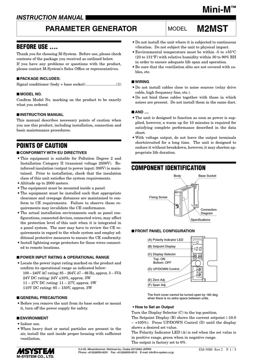
M-system Mini-M M2MST User manual

M-system

M-system Mini-M M2MST User manual

M-system Mini-M M2CDS User manual

M-system

M-system Mini-M M2CDS User manual

M-system Sentronic Mini-M M2VF2 Series User manual

M-system

M-system Sentronic Mini-M M2VF2 Series User manual

M-system Mini-M M2MLS User manual

M-system

M-system Mini-M M2MLS User manual

M-system AD2LC User manual

M-system

M-system AD2LC User manual

M-system MXCB-1 User manual

M-system

M-system MXCB-1 User manual

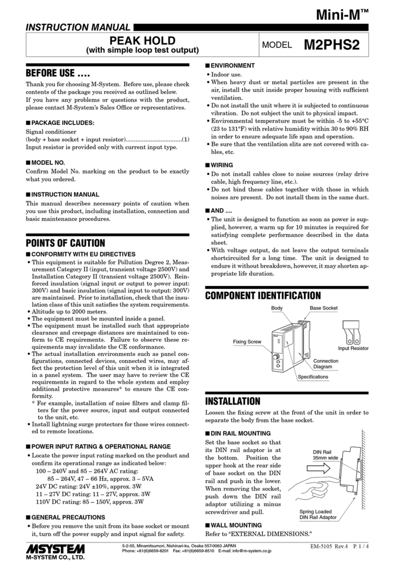
M-system Mini-M M2PHS2 User manual

M-system

M-system Mini-M M2PHS2 User manual

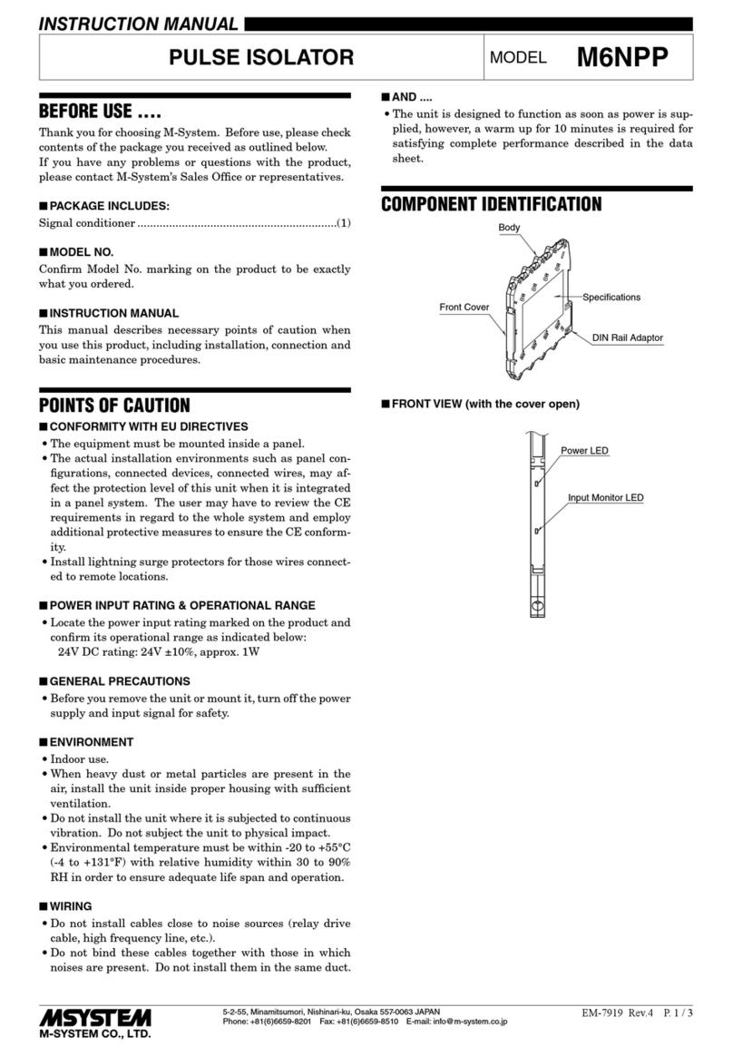
M-system M6NPP User manual

M-system

M-system M6NPP User manual

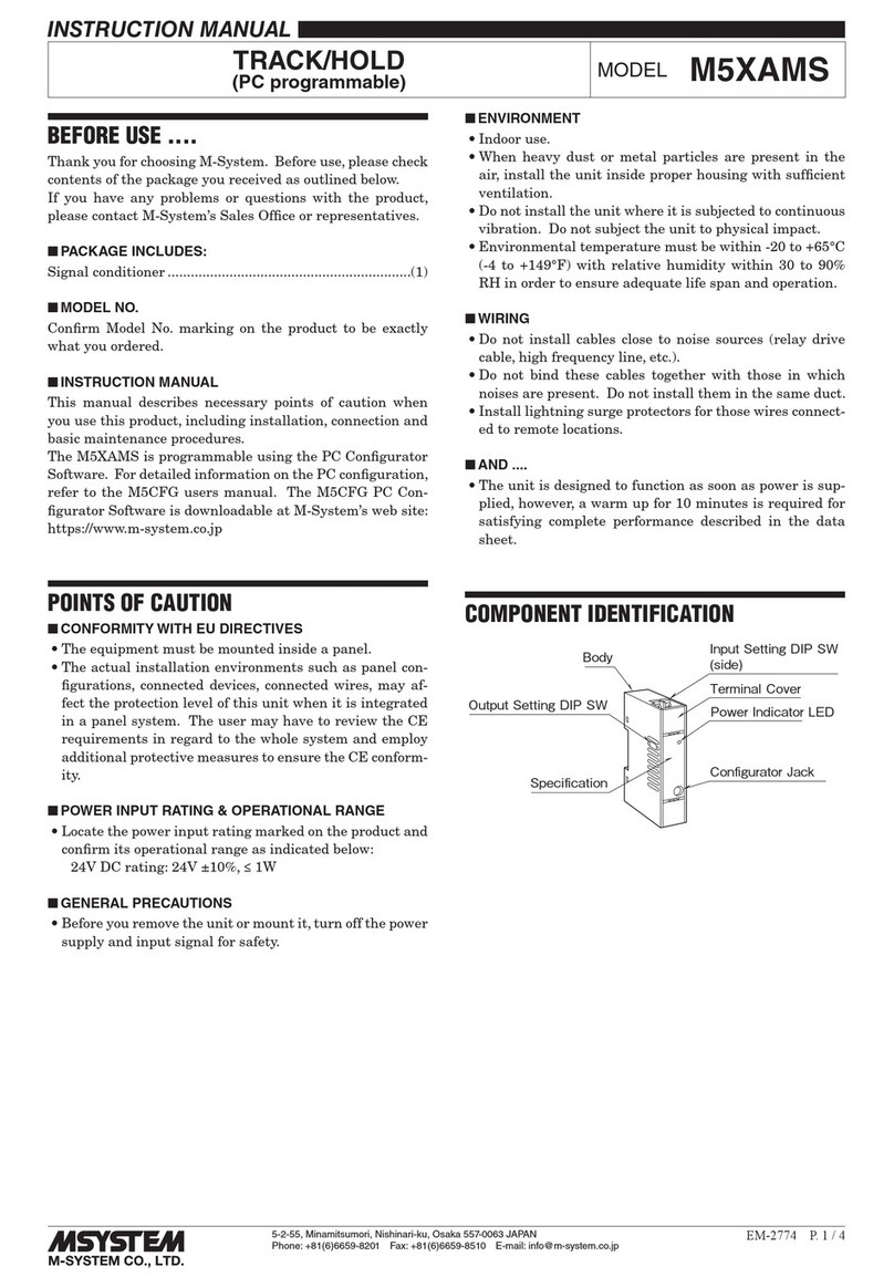
M-system M5XAMS User manual

M-system

M-system M5XAMS User manual

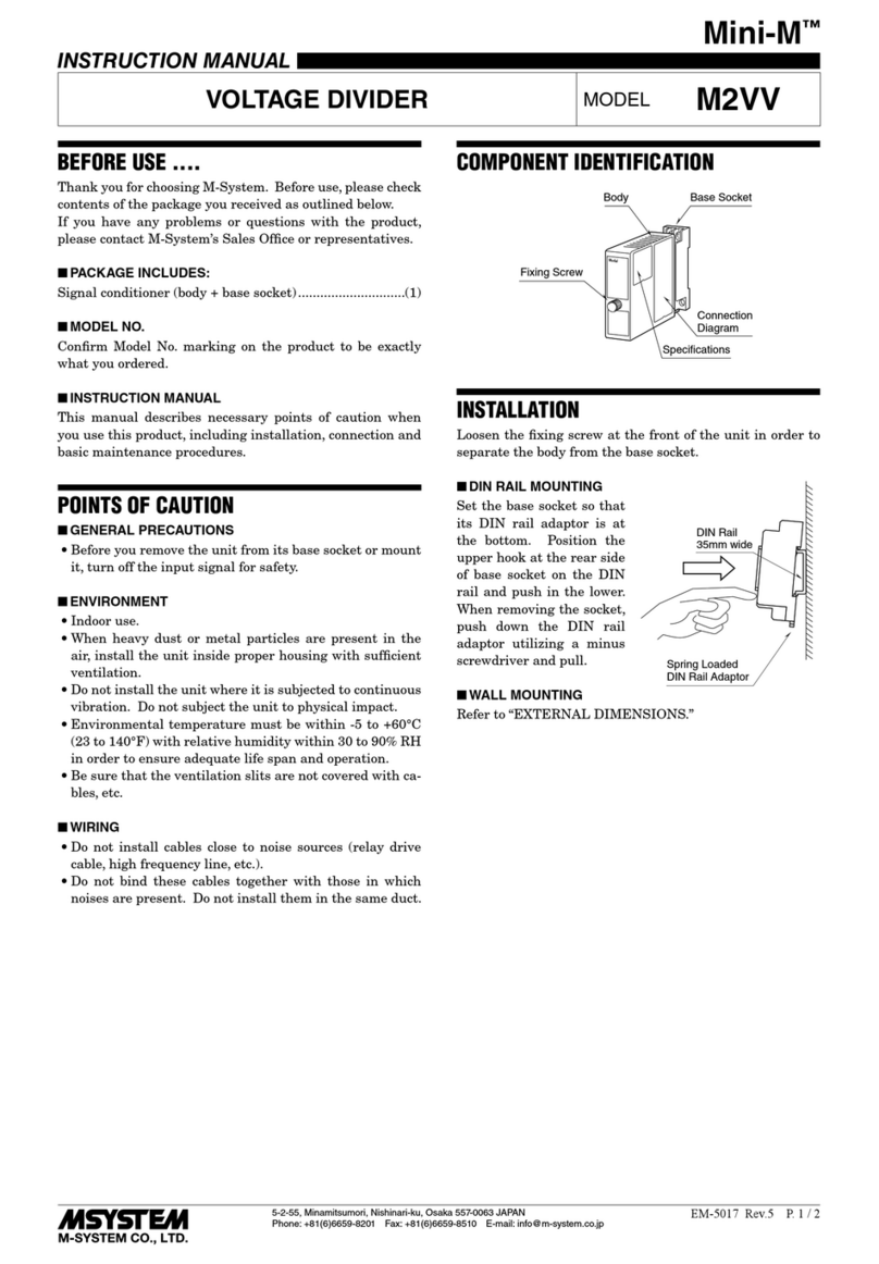
M-system Mini-M M2VV User manual

M-system

M-system Mini-M M2VV User manual

M-system FDY2 User manual

M-system

M-system FDY2 User manual

M-system M6DPP User manual

M-system

M-system M6DPP User manual

M-system M2PRU User manual

M-system

M-system M2PRU User manual

M-system Mini-M Series User manual

M-system

M-system Mini-M Series User manual

M-system FDU User manual

M-system

M-system FDU User manual

M-system Mini-M Series User manual

M-system

M-system Mini-M Series User manual

M-system Mini-M M2LMS User manual

M-system

M-system Mini-M M2LMS User manual

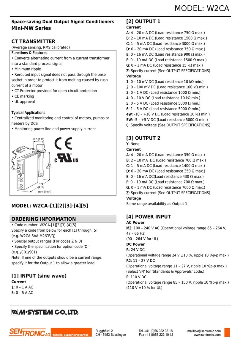
M-system Mini-MW Series User manual

M-system

M-system Mini-MW Series User manual

M-system Sentronic Mini-M M2RS Series User manual

M-system

M-system Sentronic Mini-M M2RS Series User manual

M-system Mini-M M2CRS User manual

M-system

M-system Mini-M M2CRS User manual

M-system Sentronic Mini-M M2XPA3 Series User manual

M-system

M-system Sentronic Mini-M M2XPA3 Series User manual

Popular Test Equipment manuals by other brands

Ambit P.F. Series instruction manual

Ambit

Ambit P.F. Series instruction manual

Megger BMM500 Series user guide

Megger

Megger BMM500 Series user guide

RJG Lynx Sensor Tester operating instructions

RJG

RJG Lynx Sensor Tester operating instructions

Mark-10 TT02 Series user guide

Mark-10

Mark-10 TT02 Series user guide

Martel 3001 Operator's manual

Martel

Martel 3001 Operator's manual

ElproSys DiagProg4 instruction manual

ElproSys

ElproSys DiagProg4 instruction manual

Redtech TRAILERteck T05 user manual

Redtech

Redtech TRAILERteck T05 user manual

Venmar AVS Constructo 1.0 HRV user guide

Venmar

Venmar AVS Constructo 1.0 HRV user guide

Test Instrument Solutions SafetyPAT operating manual

Test Instrument Solutions

Test Instrument Solutions SafetyPAT operating manual

Hanna Instruments HI 38078 instruction manual

Hanna Instruments

Hanna Instruments HI 38078 instruction manual

Kistler 5495C Series instruction manual

Kistler

Kistler 5495C Series instruction manual

Waygate Technologies DM5E Basic quick start guide

Waygate Technologies

Waygate Technologies DM5E Basic quick start guide

StoneL DeviceNet CK464002A manual

StoneL

StoneL DeviceNet CK464002A manual

Seica RAPID 220 Site preparation guide

Seica

Seica RAPID 220 Site preparation guide

Kingfisher KI7400 Series Training manual

Kingfisher

Kingfisher KI7400 Series Training manual

Kurth Electronic CCTS-03 operating manual

Kurth Electronic

Kurth Electronic CCTS-03 operating manual

SMART KANAAD SBT XTREME 3G Series user manual

SMART

SMART KANAAD SBT XTREME 3G Series user manual

Agilent Technologies BERT Serial Getting started

Agilent Technologies

Agilent Technologies BERT Serial Getting started

manuals.online logo
manuals.online logoBrands
  • About & Mission
  • Contact us
  • Privacy Policy
  • Terms and Conditions

Copyright 2025 Manuals.Online. All Rights Reserved.

5-2-55, Minamitsumori, Nishinari-ku, Osaka 557-0063 JAPAN
Phone: +81(6)6659-8201 Fax: +81(6)6659-8510 E-mail: info@m-system.co.jp
EM-5534 Rev.7 P. 1 / 3
INSTRUCTION MANUAL
PULSE ISOLATOR MODEL W2PP
BEFORE USE ....
Thank you for choosing M-System. Before use, please check
contents of the package you received as outlined below.
If you have any problems or questions with the product,
please contact M-System’s Sales Office or representatives.
■PACKAGE INCLUDES:
Signal conditioner (body + base socket).............................(1)
■MODEL NO.
Confirm Model No. marking on the product to be exactly
what you ordered.
■INSTRUCTION MANUAL
This manual describes necessary points of caution when
you use this product, including installation, connection and
basic maintenance procedures.
POINTS OF CAUTION
■CONFORMITY WITH EU DIRECTIVES
• This equipment is suitable for Pollution Degree 2, Meas-
urement Category II (output, transient voltage 1500V)
and Installation Category II (transient voltage 2500V).
Reinforced insulation (signal input or output 1 or output
2 to power input: 300V) and basic insulation (signal input
to output 1 or output 2: 300V) are maintained. Prior to
installation, check that the insulation class of this unit
satisfies the system requirements.
• Altitude up to 2000 meters.
• The equipment must be mounted inside a panel.
• The equipment must be installed such that appropriate
clearance and creepage distances are maintained to con-
form to CE requirements. Failure to observe these re-
quirements may invalidate the CE conformance.
• The actual installation environments such as panel con-
figurations, connected devices, connected wires, may af-
fect the protection level of this unit when it is integrated
in a panel system. The user may have to review the CE
requirements in regard to the whole system and employ
additional protective measures to ensure the CE conform-
ity.
• Install lightning surge protectors for those wires connect-
ed to remote locations.
■POWER INPUT RATING & OPERATIONAL RANGE
• Locate the power input rating marked on the product and
confirm its operational range as indicated below:
100 – 240V AC rating: 85 – 264V, 47 – 66 Hz, approx. 4 – 6VA
24V DC rating: 24V ±10%, approx. 4W
11 – 27V DC rating: 11 – 27V, approx. 4W
110V DC rating: 85 – 150V, approx. 4W
■GENERAL PRECAUTIONS
• Before you remove the unit from its base socket or mount
it, turn off the power supply and input signal for safety.
■ENVIRONMENT
• Indoor use.
• When heavy dust or metal particles are present in the
air, install the unit inside proper housing with sufficient
ventilation.
• Do not install the unit where it is subjected to continuous
vibration. Do not subject the unit to physical impact.
• Environmental temperature must be within -5 to +55°C
(23 to 131°F) with relative humidity within 30 to 90% RH
in order to ensure adequate life span and operation.
• Be sure that the ventilation slits are not covered with ca-
bles, etc.
■WIRING
• Do not install cables close to noise sources (relay drive
cable, high frequency line, etc.).
• Do not bind these cables together with those in which
noises are present. Do not install them in the same duct.
■AND ....
• The unit is designed to function as soon as power is sup-
plied, however, a warm up for 10 minutes is required for
satisfying complete performance described in the data
sheet.
COMPONENT IDENTIFICATION
Model
Fixing Screw
Connection
Diagram
Specifications
Body Base Socket
INSTALLATION
Loosen the fixing screw at the front of the unit in order to
separate the body from the base socket.
DIN Rail
35mm wide
Spring Loaded
DIN Rail Adaptor
■DIN RAIL MOUNTING
Set the base socket so that
its DIN rail adaptor is at
the bottom. Position the
upper hook at the rear side
of base socket on the DIN
rail and push in the lower.
When removing the socket,
push down the DIN rail
adaptor utilizing a minus
screwdriver and pull.
■WALL MOUNTING
Refer to “EXTERNAL DIMENSIONS.”
W2PP
5-2-55, Minamitsumori, Nishinari-ku, Osaka 557-0063 JAPAN
Phone: +81(6)6659-8201 Fax: +81(6)6659-8510 E-mail: info@m-system.co.jp
EM-5534 Rev.7 P. 2 / 3
TERMINAL CONNECTIONS
Connect the unit as in the diagram below or refer to the connection diagram on the side of the unit.
■EXTERNAL DIMENSIONS unit: mm (inch)
4
8 7
10
21.5 (.87)
88.5 (3.48)
84 (3.31)10 (.39)
22 (.87)
59 (2.32)
DIN RAIL
35mm wide
[4 (.16)]
11
–
M3
SCREW
72 (2.83)
29.5 (1.16)
53 (2.09)
2
–
4.2x5
(.17x.20)
MTG HOLE
6 (.24) deep
114 (4.49)
11
56
123
9
6 (.23)
• When mounting, no extra space is needed between units.
4
(.16)
■CONNECTION DIAGRAM
U(+)
V(–)
POWER
10
11
+
–
OUTPUT 1
7
8
+
–
3
6
OUTPUT 2
The section enclosed by broken line is only with 2nd output option.
+
–
INPUT
1
4
2
+
SENSOR EXCITATION
■ Mechanical Contact,
Open Collector or Clamp-or
Pulse Sensor CLSP
Input Connection Examples
■ Voltage Pulse
4kΩ
+12V
+
+
–
–
PWR
+
–
1
2
+4
+12V
+
+
–
–
PWR
+
–
1
2
+4
■ Open Collector
Output Connection Examples
+
–
7
8
+
–
■ Voltage Pulse
+
–
7
8
+
–
U
■ Dry Contact AC/DC Switch
• AC Powered
7
8LOAD
Relay or
Counter Coil
Varistor or Spark
Quenching Circuit
• DC Powered
7
8LOAD
Relay or
Counter Coil
Spark Quenching Diode
W2PP
5-2-55, Minamitsumori, Nishinari-ku, Osaka 557-0063 JAPAN
Phone: +81(6)6659-8201 Fax: +81(6)6659-8510 E-mail: info@m-system.co.jp
EM-5534 Rev.7 P. 3 / 3
WIRING INSTRUCTIONS
■SCREW TERMINAL
Torque: 0.8 N·m
■SOLDERLESS TERMINAL
Refer to the drawing below for recommended ring tongue
terminal size. Spade tongue type is also applicable.
Applicable wire size: 0.25 to 1.65 mm2(AWG 22 to 16)
Recommended manufacturer: Japan Solderless Terminal
MFG.Co.Ltd, Nichifu Co.,ltd
6 (.24) max
3.3 (.13) max
mm (inch)
CHECKING
1) Terminal wiring: Check that all cables are correctly con-
nected according to the connection diagram.
2) Power input voltage: Check voltage across the terminal
10 – 11 with a multimeter.
3) Input: Check that the input frequency is 30 Hz or less
for mechanical contact, 10 kHz or less for other types of
input.
Check also that the input pulse is of 10 msec. or wider
for mechanical contact, 10 µsec. or wider for other types
of input.
4) Output: Check that the load resistance meets the de-
scribed specifications as shown below.
OUTPUT OUTPUT LOAD
Low freq. open collector 50 V DC @ 100 mA max.
High freq. open collector
50V DC @ 100 mA max.
Voltage pulse 5V 250 Ω minimum
12V 600 Ω minimum
24V 1200 Ω minimum, output 1
2400 Ω minimum, output 2
Dry contact AC/DC switch
132 V AC @ 200 mA (cosø=1)
30 V DC @ 200 mA (resistive load)
LIGHTNING SURGE PROTECTION
M-System offers a series of lightning surge protector for
protection against induced lightning surges. Please contact
M-System to choose appropriate models.