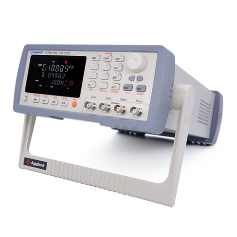
Applent Instruments AT851 User manual

!$Instruments
©2005-2011 Applent Instruments
English
Revision A5
FIRMWARE REVISIONS
This manual applies directly to instruments that
have the firmware Rev. A
[AT851 Battery Aging Tester]
User’s Guide
길 우 트 레 이 딩
서울특별시 영등포구 선유로33길 15
703호(양평동3가, 에이스테크노타워)<150-962>
02)2636-0009 팩스02)2636-4753
www.gilwoo.co.kr [email protected]
www.gilwooshop.co.kr

AT8511/8512 User’s Guide
2
Safety Summary
Warning Dangerous:
When you notice any of the unusual conditions listed below, immediately terminate operation and disconnect the
power cable.
Please Contact Applent Instruments Incorporation sales representative for repair of the instrument. If you continue
to operate without repairing the instrument, there is a potential fire or shock hazard for operators.
Instrument operates abnormally.
Instrument emits abnormal noise, smell, smoke, or a spark-like light during the operation.
Instrument generates high temperature or electrical shock during operation.
Power cable, plug, or receptacle on instrument is damaged.
Foreign substance or liquid has fallen into the instrument.
The following general safety precautions must be observed during all phases of operation, service, and repair of
this instrument. Failure to comply with these precautions or with specific WARNINGS elsewhere in this manual
may impair the protection provided by the equipment. In addition it violates safety standards of design,
manufacture, and intended use of the instrument.
Disclaimer
Applent Instruments assumes no liability for the customer's failure to
comply with these requirements.
Ground
The Instrument
To avoid electric shock hazard, the instrument chassis and cabinet must be
connected to a safet
y earth ground by the supplied power cable with earth
blade.
DO NOT
Operate In An Explosive
Atmosphere
Do not operate the instrument in the presence of inflammable gasses or
fumes. Operation of any electrical instrument in such an environment
constitutes a definite safety hazard.
Keep Away
From Live
Circuits
Operating personnel must not remove instrument covers. Component
replacement and internal adjustments must be made by qualified
maintenance personnel. Do not replace components with the power cable
connected. Under certain conditions, dangerous voltages may exist even
with the power cable removed. To avoid injuries, always disconnect power
and discharge circuits before touching them.
DO NOT
Service Or Adjust Alone
Do not attempt internal service o
r adjustment unless another person,
capable of rendering first aid and resuscitation, is present.
DO NOT
Substitute Parts Or
Modify Instrument
Because of the danger of introducing additional hazards, do not install
substitute parts or perform unauthori
zed modifications to the instrument.
Return the instrument to an Applent Instruments Sales and Service Office
for service and repair to ensure that safety features are maintained.

3
Unpacking and Preparation
CERTIFICATION, LIMITED WARRANTY, & LIMITATION OF
LIABILITY
Applent Instruments, Inc. (shortened form Applent)certifies that this product met its published specifications
at the time of shipment from the factory. Applent further certifies that its calibration measurements are traceable to
the People’s Republic of China National Institute of Standards and Technology, to the extent allowed by the
Institution’s calibration facility or by the calibration facilities of other International Standards Organization
members.
This Applent instrument product is warranted against defects in material and workmanship for a period
corresponding to the individual warranty periods of its component products. The warranty period is 1 years and
begins on the date of shipment. During the warranty period, Applent will, at its option, either repair or replace
products that prove to be defective. This warranty extends only to the original buyer or end-user customer of a
Applent authorized reseller, and does not apply to fuses, disposable batteries or to any product which, in Applent’s
opinion, has been misused, altered, neglected or damaged by accident or abnormal conditions of operation or
handling.
For warranty service or repair, this product must be returned to a service facility designated by Applent. The buyer
shall prepay shipping charges to Applent and Applent shall pay shipping charges to return the product to the Buyer.
However, the Buyer shall pay all shipping charges, duties, and taxes for products returned to Applent from another
country.
Applent warrants that its software and firmware designated by Applent for use with an instrument will execute its
programming instruction when properly installed on that instrument. Applent does not warrant that the operation
of the instrument, or software, or firmware, will be uninterrupted or error free.
The foregoing warranty shall not apply to defects resulting from improper or inadequate maintenance by the
Buyer, Buyer-supplied software or interfacing, unauthorized modification or misuse, operation outside the
environmental specifications for the product, or improper site preparation or maintenance.
THIS WARRANTY IS BUYER’S SOLE AND EXCLUSIVE REMEDY AND IS IN LIEU OF ALL OTHER
WARRANTIES, EXPRESS OR IMPLIED, INCLUDING BUT NOT LIMITED TO ANY IMPLIED
WARRANTY OF MERCHANTABILITY OR FITNESS FOR A PARTICULAR PURPOSE. APPLENT SHALL
NOT BE LIABLE FOR ANY SPECIAL, INDIRECT, INCIDENTAL OR CONSEQUENTIAL DAMAGES OR
LOSSES, INCLUDING LOSS OF DATA, WHETHER ARISING FROM BREACH OF WARRANTY OR
BASED ON CONTRACT, TORT, RELIANCE OR ANY OTHER THEORY.
Applent Instruments, Inc.
Changzhou,
Jiangsu,
China,
Rev.A2 January, 2005
Rev.B0 January, 2008

4
AT851 Battery Aging Tester
Contents
Safety Summary ........................................................................................................................................................ 2
CERTIFICATION, LIMITED WARRANTY, & LIMITATION OF LIABILITY ..................................................... 3
Contents............................................................................................................................................................. 4
1. Unpacking and Preparation................................................................................................................................ 6
1.1 Incoming Inspection .......................................................................................................................... 6
1.2 Setting up Fuse .................................................................................................................................. 6
1.3 Environmental Requirements ............................................................................................................ 6
1.4 Cleaning............................................................................................................................................. 7
1.5 How to Remove the Handle............................................................................................................... 7
2. Overview ........................................................................................................................................................... 9
2.1 Main Specification............................................................................................................................. 9
2.2 Features.............................................................................................................................................. 9
3. Start up............................................................................................................................................................. 10
3.1 Front panel ....................................................................................................................................... 10
3.2 VFD ................................................................................................................................................. 10
3.3 Keypad ..............................................................................................................................................11
3.4 Real panel ........................................................................................................................................ 12
3.5 Power On/Off................................................................................................................................... 13
3.5.1 Warm-up Time ......................................................................................................................... 13
3.6 Application Connections.................................................................................................................. 13
3.6.1 Wiring Considerations ............................................................................................................. 13
3.6.2 Local Sense Connections ......................................................................................................... 13
3.6.3 Remote Sensing Connections .................................................................................................. 14
3.7 Turning the Input On/off.................................................................................................................. 15
3.8 Operation Range .............................................................................................................................. 15
3.9 Protection Features .......................................................................................................................... 16
3.9.1 Over Voltage [-OV-].................................................................................................................. 16
3.9.2 Over Current [-OC-].................................................................................................................. 16
3.9.3 Over Power [-OP-] ................................................................................................................... 16
3.9.4 Reverse Voltage [-RV-]............................................................................................................. 16
3.9.5 Over Heat [-OH-] ...................................................................................................................... 17
4. Basic Operation ............................................................................................................................................... 18
4.1 Modes of Operation ......................................................................................................................... 18
4.1.1 Constant Current Mode [CC]................................................................................................... 18
4.1.2 Constant Voltage Mode (CV)................................................................................................... 19
4.1.3 Constant Power Mode (CP) ..................................................................................................... 19
4.1.4 Constant Resistance Mode (CR).............................................................................................. 20
4.2 Functions of Operation .................................................................................................................... 21
4.3 Setup the Maximum Current [I-max] .............................................................................................. 21
4.4 Setup the Maximum Voltage [V-max] ............................................................................................. 22
4.5 Setup the Maximum Power [P-max]................................................................................................ 22
4.6 Von/off Operation ............................................................................................................................ 22
4.7 Load ON Timer Function................................................................................................................. 23
4.8 File Operation (Saving/Loading/Erasing Settings).......................................................................... 23
4.9 Display Power or Resistance Measurement Result.......................................................................... 24
4.10 Menu................................................................................................................................................ 24
5. Advanced Testing Function ............................................................................................................................. 26
5.1 Short Circuit On/Off (SHT)............................................................................................................. 26
5.2 Battery Testing Function (BAT)....................................................................................................... 26
5.2.1 Set up battery testing parameter............................................................................................... 26
5.3 Battery Aging Testing Function ....................................................................................................... 27
5.3.1 Set up the parameters............................................................................................................... 27
5.3.2 Start the test ............................................................................................................................. 28
5.3.3 List of test data......................................................................................................................... 28
5.3.4 Testing Process ........................................................................................................................ 29
6. Specification .................................................................................................................................................... 30

5
Unpacking and Preparation
6.1 Specification .................................................................................................................................... 30
6.2 General Specification....................................................................................................................... 30
6.3 Dimensions ...................................................................................................................................... 31
Figure Contents
Figure 1-1 Fuse Holder...................................................................................................................................... 6
Figure 3-1 Front panel ..................................................................................................................................... 10
Figure 3-2 VFD................................................................................................................................................ 10
Figure 3-3 Keypad I..........................................................................................................................................11
Figure 3-4 Keypad II ....................................................................................................................................... 12
Figure 3-5 Real panel....................................................................................................................................... 12
Figure 3-6 Local Sensing................................................................................................................................. 13
Figure 3-7 The remote sensing interface on real panel.................................................................................... 14
Figure 3-8 Remote Sensing ............................................................................................................................. 14
Figure 3-9 The Input State ............................................................................................................................... 15
Figure 3-10 Rate power and Power Limit ....................................................................................................... 16
Figure 4-1 Constant Current Mode.................................................................................................................. 18
Figure 4-3 Constant Voltage Mode .................................................................................................................. 19
Figure 4-4 Constant power Mode .................................................................................................................... 20
Figure 4-5 Constant Resistance Mode ............................................................................................................. 20
Figure 4-6 Functions of Operation................................................................................................................... 21
Figure 4-7 I-max Setup Page ........................................................................................................................... 21
Figure 4-8 Von/off Operation........................................................................................................................... 22
Figure 4-9 V-ON Setup Page ........................................................................................................................... 23
Figure 4-10 V-OFF Setup Page........................................................................................................................ 23
Figure 4-11 Load ON Timer Setup Page ......................................................................................................... 23
Figure 4-12 File Operation Page...................................................................................................................... 24
Figure 5-8 Short-Circuit Testing Page ............................................................................................................. 26
Figure 5-9 Set up Discharge Current ............................................................................................................... 27
Figure 5-10 Set up cut-off voltage ................................................................................................................... 27
Figure 5-11 Battery Testing Function Page ..................................................................................................... 27
Table Contents
Table 3-1 VFD Description...............................................................................................................................11
Table 3-2 Keypad description.......................................................................................................................... 12
Table 4-1 Setup input current (I-Set) by using numeric keypad ...................................................................... 18
Table 4-2 Setup voltage (V-Set) by using numeric keypad.............................................................................. 19
Table 4-3 Setup power value(P-Set) by using numeric keypad ....................................................................... 20
Table 4-3 Setup resistance value(R-Set) by using numeric keypad................................................................. 21
Table 4-2 File Operation .................................................................................................................................. 24
Table 4-3 Menu operation................................................................................................................................ 24

6
AT851 Battery Aging Tester
1. Unpacking and Preparation
!
This chapter describes how to set up and start the AT 85 1 .
Incoming Inspection
Power Requirements
Setting up the Fuse
How to Remove the Handle
Environmental Requirements
Cleaning
1.1 Incoming Inspection
After you have received the instrument, carry out inspection during unpacking
according to the following procedures.
WARNING
If the extern
al face of the instrument (such as the cover, front/rear panel, VFD screen,
power switch, and port connectors) appears damaged during transport, do not turn on the
power switch, in case that get an electrical shock.
Check whether the packing box or shock-absorbing material used packaging the
instrument has been damaged.
Referring to <Packing List> in the packing box, check whether all packaged items
supplied together with the meter have been provided as per the specified optioned.
1.2 Setting up Fuse
Figure 1-1
Fuse Holder
~Line: 110VA C /220V AC
20 VA M A X
Fuse: 250V 1A
Slow Blow
Please use the following fuse type.
UL/CSA type, Slow-Blow, 5×20-mm miniature fuse, 1A,
250 V
To verify and replace the fuse, remove the power cable and pull out the fuse holder.
Two fuses in Fuse Holder.
1.3 Environmental Requirements
Set up the AT 8 5 1 according to following environmental requirements.

7
Unpacking and Preparation
Operating Environments
Ensure the operating environment meets the following requirements.
Temperature: 0°C to 55°C
Temperature range at calibration: 23°C±5°C (<1°C deviation from the temperature
when performing calibration)
Humidity: 15% to 85% at wet bulb temperature ≤40°C (non-condensation)
Altitude: 0 to 2,000m
Vibration: Max. 0.5 G, 5 Hz to 500 Hz
1.4 Cleaning
To prevent electrical shock, disconnect the AT 8 5 1 power cable from the receptacle
before cleaning.
Use dry cloths or cloths slightly dipped in water to clean the case.
Do not attempt to clean the internal of the AT851.
WARNING: Don’t Use Organic Solvents (such as alcohol or gasoline) to clean the
Instrument.
1.5 How to Remove the Handle
A handle kit is attached to the AT 8 51:
1 Retracted
3 Carrying Position
2 Extended

8
AT851 Battery Aging Tester
Remove Handle(Lift the handle perpendicular to the unit while pulling it in the direction of 1.)

Overview
9
2. Overview
This chapter contains general information about Z9500 .The information is organized
as follows
Introduction
Main Specifications
Feature overview
2.1 Main Specification
DC INPUT RATE: AT8511:150W/120V/30A,8512:300W/120V/30A
CONSTANT CURRENT: 0~30A
Accuracy:0.2%
CONSTANCE VOLTAGE: 0~120V
Accuracy: 0.1%
CONSTANCE POWER: 0~150W(AT8511), 0~300W(AT8512)
Accuracy:1%
CONSTANCE RESISTANCE:0~4000Ω
Accuracy: 1%
Battery Aging Test: Discharge – Charge – Rest
Battery Aging Charge and Rest Timer: 9999 minutes
Battery Capacity: 999.99AH
Battery Discharge Timer: 999H
Maximum Loop Times: 999 times
2.2 Features
VFD Display
Operation Mode:
NORMAL (CC/CV/CP/CR) , TRANSIENT (TRN), SEQUENCE LIST (SEQ),
AUTOMATIC TESTING FUNCTION (ATF), BATTERY TESTING FUNCTION
and SHORT CIRCUIT TEST (SHT).
Protections:
Over Voltage (OV), Over Current (OC), Over Power (OP) and Over Heat (OH)
protection.

10
AT851 Battery Aging Tester
3. Start up
This chapter describes names and functions of the front panel, rear panel, and screen
display and provides the basic procedures for operating AT851.
Front panel summary
Rear panel summary
Power-up
How to connect with AT851
3.1 Front panel
Figure 3-1 Front panel
Ta b le 3-1 Front panel description
No.
Name and Description
1
POWER SWITCH. Push down: ON, Push up: OFF
2
VFD. Displaying measurement results, instrument status and user’s interface menus.
3
Knob. To choose menu item and input number
4
Terminals.
5
Keypad II, Multi-function keys: Numeric and 2nd Function.
6
Shift. Pressing this key before using 2nd Function.
7
Keypad I, Dual-Function keys: 1st Function and 2nd Function.
3.2 VFD
Figure 3-2 VFD

11
Start up
Ta b le 3-1 VFD Description
ID
Name
Description
1
Display #1
The No.1 Display Line. Display voltage measurement.
2
Display #2
The No.2 Display Line. Display current, power or resistance measurement
3 Display #3
The No.3 Display Line. Display the Operation Mode and Input ON/OFF status.
Normal Operation Mode: CC/CV/CP/CR
Transient Operation Mode: TRN
Sequence List Operation Mode: SEQ
Automatic Testing Function: AT F
Battery Testing Function: B AT
Short Circuit Operation: SHT
4,5 EX TRIG
TRIG: BUS Trigger Indicator
EX TRIG: External Trigger Indicator (See also: Trigger)
6
FMS
Rate Indicator. F: Fast, M: Medium, S: Slow
7
MAX
Maximum Value.
8
MIN
Minimum Value.
9
Shift
Lit when Shift key pressed.
10
File No.
11
DE LAY
Load on Timer Function start working.
12
VLMT
Display when Von/Voff Operation start working
13
NG GD
Display the comparator result in ATF mode.
14
4W
Remote sense function is ON.
15
Remote operation function is ON
3.3 Keypad
Figure 3-3 Keypad I

12
AT851 Battery Aging Tester
Figure 3-4 Keypad II
Ta b le 3-2 Keypad description
Key
Description
I-Set
Set up a constant current from 0 to Max current. “CC” will be shown on Display #3.
Shift+I-max
Set up Max current value. The I-Max setup page will be displayed.
V-Set
Set up a constant voltage from 0 to Max voltage. “CV” will be showed on Display #3
Shift+V-max
Set up Max voltage value. The V-MAX setup page will be displayed.
P-Set
Set up a constant power from 0 to Max Power. “CP” will be showed on Display #3.
Shift+P-max
Set up Max power value. The P-Max setup page will be displayed.
R-Set
Set up a constant resistance from 0 to 4000Ω. “CR” will be showed on Display #4
Shift+V-On/Off
Set up Von value and Voff value for Von/Off operation. “VLMT” indicator will be
showed on VFD.
File
File Save/Read/Erase Operation. The FILE setup page will be displayed.
List
Sequence List Operation. The LIST setup page will be displayed.
Rotary knob to adjust the value in Test and Setup mode.
Rotary knob to choose menu in menu mode.
Choose menu item.
Esc
Escape
Enter
Enter.
Shift+Battery
Battery Testing Mode. The “B AT ” will be showed on Display #3.
Shift+Short
Short circuit Operation Mode. The “SHT” will be showed on Display #3.
Shift+Tran
Enter Transition Operation Mode. The “TRN” will be showed on Display #3
Shift+ S-Tran
Set up the transition parameter.
Shift+Timer
Load on Timer Operation Mode. The “DELAY” indicator will be showed.
Shift+Menu
Menu List Page.
3.4 Real panel
Figure 3-5 Real panel

13
Start up
1 2 3 4
5
1. Handler Interface. (Include External Trigger Input and Remote Sense)
2. NC
3. NC
4. RS232C Interface.
5. Power Inlet (Built-In fuse type)
3.5 Power On/Off
Power On
Power Off
3.5.1 Warm-up Time
AT85 1 is ready to be used as soon as the power-up sequence has completed. However, to
achieve the accuracy rating, warm up the instrument for 30 minutes is necessary.
3.6 Application Connections
3.6.1 Wiring Considerations
WARNING
FIRE HAZARD
To satisfy safety requirements, load wires must be heavy enough to not overheated
while carrying the short-circuit output current of the device connects to AT851.
Input connections are made to the + and - binding posts on the front panel. A major
consideration in making input connections is the wire size.
The minimum wire size required to prevent overheating may not be large enough to
maintain good regulation. Stranded, copper wires are recommended to use. The wires
should be large enough to limit the voltage drop no more than 0.5 V per lead.
3.6.2 Local Sense Connections
Figure 3-6 Local Sensing

14
AT851 Battery Aging Tester
0.+/-
12 3
456
78 9
←8
INPUT
+ -
A
B
OUTPUT
+ -
TIE
WRAPS
DC Power Supply
+CV SOURCE)
3.6.3 Remote Sensing Connections
The remote sense terminals of AT851 are connected to the output of the power supply.
Remote sensing compensates for the voltage drop in applications require long lead
lengths.
Before using remote sensing connections, you must set the MENU-SENSE to ON state.
A “4W” indicator will be displayed on VFD.
Figure 3-7 The remote
sensing interface on
real panel.
+-
GND
TRIG
SENSE
TRIGGER
Figure 3-8 Remote Sensing

15
Start up
Shift
0.+/-
12 3
456
78 9
←
8
INPUT
+ -
A
B
OUTPUT
+ -
TIE
WRAPS
DC POWER SOURCE
REAL
PANEL
+-
+
-
3.7 Turning the Input On/off
Figure 3-9 Input On/Off switchers on front panel
The Input can be toggled on and off by pressing ESC(ON/OFF) key.
The Input state “ON” or “OFF” will be displayed on display #3.
Figure 3-9
The Input State
3.8 Operation Range

16
AT851 Battery Aging Tester
Figure 3-10
Rate power and
Power Limit
Input
Voltage+V)
Input Current +I)
Rated Power
Rated
Voltage
Rated Current
Input
Voltage+V)
Input Current +I)
Rated
Voltage
Rated Current
Current Limit
Power Limit
3.9 Protection Features
AT85 1 includes five protection features.
3.9.1 Over Voltage [
-OV-
]
Load input will be turned OFF immediately if input voltage exceeds the 105%*V-MAX.
The buzzer beeps, “-OV-” is displayed on display #3 and indicator flashes.
3.9.2 Over Current [
-OC-
]
When work in the CR or CC and CP mode, input current is ascending continuously and
the load current will be limited to I-MAX value. Load will work in the OC protection
state and -OC-will be displayed on display #3.
In the CV mode, transition mode and list mode, the buzzer beeps and -OC-will been
displayed once input current exceeds the 102%*I-MAX.
3.9.3 Over Power [
-OP-
]
CV mode:
If the input power exceeds the power limit (101%*P-MAX), load will work in the over
power protection state. The buzzer beeps, current value will be flashed and -OP- will be
displayed.
If the input power exceeds the power limit (102%*P-MAX), load will be turned off.
CC, CP and CR mode:
If the input power exceeds the power limit (102%*P-MAX), load will work in the over
power protection state. Voltage and current value will be flashed and -OP- will be
displayed. But the buzzer is silent.
3.9.4 Reverse Voltage [
-RV-
]
This feature protects the load module in case of the input DC voltage lines are
connected with wrong polarity.
Once a reverse voltage condition detected, Buzzer beeps and -RV-will be displayed,
and input will turn off immediately.

17
Start up
3.9.5 Over Heat [
-OH-
]
Once the load internal power devices’ temperature exceeds the safe limits (80°C), load
input will turn off, -OH-will be displayed on VFD, and buzzer beeps.

18
AT851 Battery Aging Tester
4. Basic Operation
This section includes the following information:
•CC/CV/CP/CR Operation Mode
•Setup the Maximum Value
•Von/off Operation
•Load ON Timer Function
•File Operation
•Menu Operation
4.1 Modes of Operation
The four modes of operation are:
Constant Current (CC)
Constant Voltage (CV)
Constant Power (CP)
Constant Resistance (CR)
4.1.1 Constant Current Mode [CC]
In CC mode, the load will sink a current in accordance with the programmed value
regardless of the input voltage. (See following figure)
Figure 4-1
Constant Current
Mode
Setting
Current
Load
Current +I)
Load Input Voltage+V)
AT85 1 provides two methods to set the current value by using the numeric keypad and
the knob.
Method 1: Setup the current value by using the numeric keypad
Table 4-1 Setup input current (I-Set) by using numeric keypad
Procedure
Operation details
Display
Step 1
Press I-Set
If the mode is not the CC
mode Press I-Set again
Step 2
Enter a new value using numeric keypad or rotary the knob to adjust the value.

19
Basic Operation
Example: press key
1
.
2
Step 3
Press
Enter
to confirm this input
Method 2: Setup the current value by using knob.
The value can be continually changed from the previews value according the knob
rotation.
The knob rotation magnification can be set in Menu-Knob item.
4.1.2 Constant Voltage Mode (CV)
In CV mode, AT 8 5 1 will sink enough current to control the source voltage to the
programmed value.
AT85 1 acts as a shunt voltage regulator when operating in the CV mode.
Figure 4-2
Constant Voltage Mode
Setting Voltage
Load
Current+ I )
Input Voltage
AT85 1 provides two methods to set the voltage value by using the numeric keypad and
the knob.
Method 1: Setup the voltage value by using the numeric keypad
Table 4-2 Setup voltage (V-Set) by using numeric keypad
Procedure
Operation details
Step 1
Press
V-Set
If the mode is not the CV mode, press
V-Set again.
Step 2
Enter a new value using numeric keypad or rotary the knob to adjust the value.
Example: press key
1
0
.
5
Step 3
Press
Enter
to confirm this input
Method 2: Setup the voltage value by using knob.
The value can be continually changed from the previews value according the knob
rotation.
The knob rotation magnification can be set in Menu-Knob item.
4.1.3 Constant Power Mode (CP)
In CP mode, AT 8 5 1 will consumption power accordance with the programmed value
regardless of the input voltage.
According to the formula P=U*I, if input voltage (U) increases, the current (I) must be
decreased to satisfy the constant power value.

20
AT851 Battery Aging Tester
Figure 4-3
Constant power Mode
V1
Load
Current +I)
V
V2
I1
I2
AT85 1 provides two methods to set the power value by using the numeric keypad and
the knob.
Method 1: Setup the power value by using the numeric keypad
Table 4-3 Setup power value(P-Set) by using numeric keypad
Procedure
Operation details
Step 1
Press
P-Set
If the mode is not the CP mode, press
P-Set again.
Step 2
Enter a new value using numeric keypad or rotary the knob to adjust the value.
Example: press key
1
0
.
5
Step 3
Press
Enter
to confirm this input
Method 2: Setup the power value by using knob.
The value can be continually changed from the previews value according the knob
rotation.
The knob rotation magnification can be set in Menu-Knob item.
4.1.4 Constant Resistance Mode (CR)
In CR mode, AT851 will sink a current linearly proportional to the input voltage in
accordance with the programmed resistance.
According to the formula R=U/I, if input voltage (U) increases, the current (I) must be
decreased to satisfy the constant resistance value.
Figure 4-4
Constant Resistance
Mode
Load
Current+I)
Input Voltage+V)
Slope Resistance Setting
AT85 1 provides two methods to set the resistance value by using the numeric keypad
and the knob.
This manual suits for next models
2
Table of contents
Other Applent Instruments Test Equipment manuals