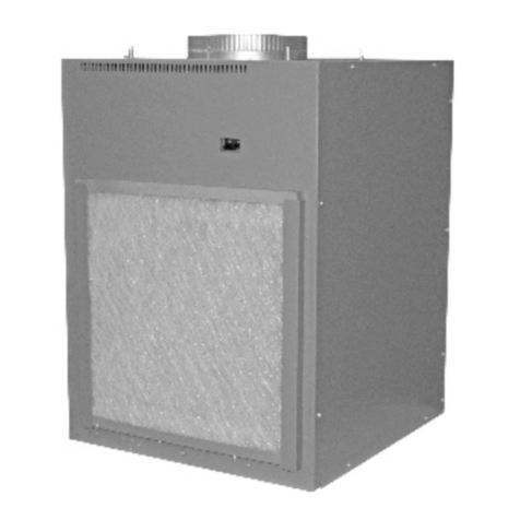
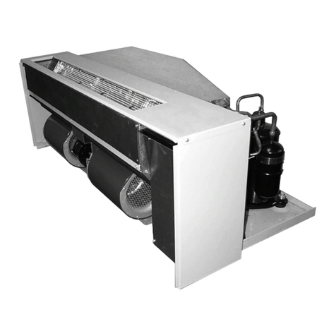
Applied Comfort VF20HA09K36E7M90 Service manual

ATTENTION INSTALLATION PROFESSIONAL
is
VF20HA09K36E7M90
VF20HA12K36E7M90
VF20HA18K50E8M80
MODELS SERIES

-1-
WARNING
RECOGNIZE THIS SYMBOL AS
A SAFETY PRECAUTION
WARNING
The manufacturer will not be responsible for any injury or
property, damage arising from improper service or service
procedures. If you install or perform service on this unit, you
assume responsibility for any personal injury or property
damage which may Many jurisdictionsresult.
require a license to install or service heating and air
conditioning equipment.
WARNING
WARNING
Risk of electric shock can cause injury or death. For
your safety, the information in this manual must be followed
to minimize the risk of fire, electric shock or personal injury.
Instruction Section in
this manual.
present.
Failure

OPERATION INSTRUCTION
-2-
Controls-terminal connections
side
shipping
screws
side
shipping
screws
R FD GH B Y W GL C
Orange-Low fan speed
Red-24VAC
Front Desk Control
Green-High fan speed
Blue-Reversing valve
Yellow-Compressor
White-Heater
Black-Common ground
ON/OFF switches
ON/OFF
Switch
six
terminals
are still HOT and must not be touched.
servicing.

Turn off the Unit and disconnect the power supply before cleaning
-3-
Remove filter
Unit-mounted filter
Filter
Return air grille
with filter holder
Filter
Access-panel with
return air grille and filter holder
To remove
and replace
the filter:
outdoor coil
Have the coils been cleaned regularly?
Drain
Clean the drain system regularly to prevent
clogging.
Air Filters
To maintain optimum performance, change the
filter at least every 30 days. The most important
thing you can do to maintain the unit is to change
the filter at least every 30 days. Dirty filters reduce
cooling, heating and air flow.
Changing the filter will:
Decrease cost of operation, save energy, prevent
clogged heat exchanger coils and reduce the risk
of premature component failure.
The coils on the unit should be checked
regularly. If they are clogged with dirt or soot,
they may be professionally cleaned.You will
need to remove the unit from the case to
inspect the coils because the dirt build-up
occurs on the coil face that first contacts the
debris.
Operating without the filter in place or with a
damaged filter will allow dirt and dust to reach
the indoor coil and reduce the cooling,heating
airflow and efficiency of the unit.
Replacement filters should be purchased from
your local retailer where air conditioner and
furnace accessories are sold.
Filter size required is 20"x 20"x1",except for
Access-panel with return air grille and filter
holder which requires a 24″×30″×1″ size.

INSTALLATION INSTRUCTION
BEFORE YOU BEGIN
Read these instructions completely and carefully.
This air conditioner is not meant to provide
unattended cooling or life support for persons
or animals who are unable to react to the
failure of the product.
The failur unattended air conditioner e of an
may result in extreme heat in the conditioned
space causing overheating or death of
persons or animals.
-4-
RISK OF ELECTRIC SHOCK.
All electrical connections and w i r i n g MUST
be installed by a qualified electrician.
Follow the National Electrical Code (NEC), the
Canadian Electrical Code (CEC) , a n d / o r
local codes and ordinances, as applicable.
For personal safety, this unit and case must be
properly grounded.
Protective devices (fuses or circuit breakers)
acceptable for unit installations are specified
on the nameplate of each unit.
Do not use an extension cord with this unit.
Aluminum building wiring may
present special problems - consult a qualified
electrician.
When the unit is not running there is still voltage
to the electrical controls.
Disconnect the power to the unit before
servicing by:
1. Removing the power cord from the wall
receptacle if unit has a cord.
OR
2. Removing the branch circuit fuses or turning
the circuit breakers off at the panel.

INSTALLATION INSTRUCTION
Electrical Requirement
WARNING
To avoid the risk of property damage,
personal injury or fire, use only copper
conductors.
To avoid property damage, personal injury
or death due to electrical shock, do not use
an extension cord with this unit.
WARNING
To avoid the risk of property damage,
personal injury or fire do not install with
power cord stretched or under a strain as
this may create loose plug/receptacle
connection.
WARNING
-5-
All wiring , including installation of the receptacle,
must be in accordance with the NEC, CEC and local
codes ordinances and regulations , as applicable.
LCDI power Cord
Unit Voltage
Rating Minimum Maximum
230/208 187 253
265 238 292
Operating Voltage
Voltage Utilization Range
230/208V 15Amp Perpendicular
230/208V 20 Amp Large tandem
230/208V 30Amp
WARNING
The power cord is located inside the electrical
control box cover for insert mounting.
LCDI Power cord
WARNING
To avoid the risk of property damage, personal injury
or death due to fire, ensure that the Case, Unit, and
Front Case Panel are replaced as a complete assembly
in a retrofit/ replacement situation. Do not under any
circumstances insert this Unit into an existing
competitor case. For example, some existing cases
may contain plastics that are incompatible with this
unit from a safety standpoint.
• LCDI Cords(230/208V models only)-
Underwriters Laboratories and the National Electric
Code (NEC) now require power cords that sense
current leakage and can open the electrical circuit to
the unit on units rated at 250 volts or less. In the event
that unit does not operate, check the reset button
located on or near the head of the power cord as part
of the normal troubleshooting procedure.
WARNING
To avoid the risk of personal injury, wiring
to the unit must be properly polarized and
grounded.
•Cord connection to a wall socket is not permitted
for 265V units. All 265V units must be hard wired
using the hard wire kit. HIGH VOLTAGE
Disconnect all power before servicing or
installing this unit multiple power sources
be present. Failure to do so may cause
property damage , personal injury or death.
Do not service this unit without first
shutting off the power to the unit from the
circuit breaker and/or removing the unit
cord set plug from the wall outlet.

-6-
Unit Component
Case
Unit
Front Case Panel
Required Accessories
(Check the"Essential Elements"label on the unit.)
Architectural Louver
Cutout
Dimensions:
20" W x 32 1/4"H
Wall Plenum
6"D x 19-3/4 "W x 32"H
8"D x 19-3/4"W x 32"H
12"D x 19-3/4"W x 32"H
15"D x 19-3/4"W x 32"H
Access Panel with
Return Air Grille
with filter holder
Cutout
Dimensions:
30"5/16Wx 48"5/16H
33"
51" Return Air Grille
with filter holder
Cutout
Dimensions:
20"5/16Wx 20"5/16H
22-7/8"
22-7/8"

-7-
~2-1/4" ~1"
11-1/2"
10" 10"
duct
3"min.
3"
min. Electrical connection
4" min.
Door/access panel
Thermostat
Connection
Unit
front
Architectural Louver
UNIT INSTALLED THROUGH
SIDE OF CASE
Top View
~2-1/4" ~1"
11-1/2"
10" 10"
duct
5"min.
3"
min. Electrical connection
5" min.
Architectural Louver
Door/access panel
Thermostat
Connection Unit
front
A
B
A Minimum recommended access door width: 30"
B Minimum recommended access door height : 50"
Option 2
Return air grille
Inside wall
Option 1
Access panel
with return air grille
Rigid
ductwork
metal duct
Air discharge
outlet
Unit
Wall
plenum
Wall plenum
divider
Drain fittings 3/4"
Filter bracket
Secure platform
to the floor
8"min.
for drain
access
Platform: 23-1/4"x 23-1/4"square Min.
load capacity:175 Ibs.
Outside wall
Plenum
cutout
32-1/4"H
x 20"W
Exterior/Outside
Bottom of case approx.2"
above bottom of plenum
Wall plenum
Bottom of case approx 2”
above bottom of plenum
Platform
Outside wall
Field supplied
outer flashing
•4" min. from front of case - Unit
installed through FRONT of case.
•5" min. from front of case - Unit
installed through SIDE of case.
•3" min. from two sides of case.
(5"for side install).
31"
2" min
10" max
1/4 " BEYOND
FLASHING

Utility Closet Connection Locations
-8-
IMPORTANT: Plan and locate plenum, wall plug, drains and thermostat carefully to avoid
interference. Hard-to-reach locations will make installation and service difficult!
Reference Dimensions
A Thermostat cable
B Power cord: 60" long if 230VAC or
conduit entrance if 265VAC.
C Case width and depth: 23-1/8"
D Case height: 31"
E Condensate drains: 3/4"connector
• Primary Drain - Centerline of
cutout is approximately 5-1/4"
from left case wall and 8-1/2" from
back case wall.
• Secondary Drain-centerline of
cutout is approximately 6-1/2"
from left case wall and 5-1/4" from
back case wall.
F Typical wall plug: 6"-12" above case
G 40" min.
Air outlet
Flex duct may be used
for transitions only
Use rigid duct for
90° bends and tees
Outside wall
A
B
CC
D
E
Platform
F
G
Connecting the
air outlet
Connecting the
air outlet
WARNING
Supply duct is intended to distribute
conditioned air throughout a single
unit on one floor only. Unit space may
be partitioned into rooms within the
same unit, but supply air is not to be
delivered to any other unit.
Provide adequate return air paths for
rooms by established means. Do not
attach a return air duct to the chassis
or outer case.
WARNING
230/208VAC
Wall receptacle for cord and
plug connection as applicable

Return Air Grille Installation Options
The room return air grille may be installed toward the front or either side of the unit.
Improper return air arrangements will cause performance problems.
There are three indoor return air grille installation options. Choose the option that best
suits your installation requirements. Follow the Installation Instructions provided with the
return air grille accessory for installation details.
NOTE: Use only one filter in the installation. The filter may be installed on the unit or in
the access panel/door.
Outside wall
Access panel with return air grille
with filter holder
Filter
Option 1
Return air grille
with filter holder
Filter
Option 2
Unit-mounted filter with a field-supplied return
air grille and access door/panel
Filter
Option 3
-9-

Wall Plenum And Architectural Louver Installation
Since the unit itself does not install in the wall opening, the use of a plenum is necessary to
contain and separate the outdoor air paths. The plenum must be able to hold water in the
bottom without leaking into the wall cavity. It also must have a “splitter” to separate the outdoor
air paths and prevent the discharge air from being drawn back into the unit.
The wall plenum is the first component to be installed. The wall opening location for the
plenum needs to extend 1” below the top of the installation platform. Since the platform must
be a minimum of 8” off the floor, the cutout for the plenum must be a minimum of 7” off the
interior finished floor. Four sizes of plenums are available,
and the choice of the correct plenum is determined by the thickness of the building exterior
wall. Each of the plenums is 19-3/4”W x 32”H and requires a 20”W x 32-1/4”H cutout in the wall.
The plenum is to be installed square and level in the ope 1/4 bubble tilt to ning or up to
outside; pitch to outside should be similar to that planned for the sleeve) and secured to the wall
construction with screws or nails in the sides located a minimum of 2” from the bottom of the
plenum. No nails or screws may be used in the bottom or top of the plenum to prevent water
entering the wall cavity.
The plenum is not load bearing, so a proper header needs to be installed above the plenum
the same as over any window opening in the wall. If the building construction is brick, concrete
block or other non self-supporting material, a lintel must be installed over the plenum opening.
The plenum must be caulked to the wall, both to outdoor wall face and to the interior wall, along
all four sides to prevent air and water infiltration. The installation of flashing, with a 45°drip lip,
is recommended under the plenum.
Architectural Louver
Proper header for
structural support
Apply proper caulking
and flashing
Exterior/Outside Wall
Properly square
and level plenum.
Wall Plenum
6"D x 19-3/4"W x 32"H
8"D x 19-3/4"W x 32"H
12"D x 19-3/4"W x 32"H
15"D x 19-3/4"W x 32"H
Case
-10-

Left side of platform
23-1/4 "min.
8" min
for
drain
access
NOTE: Specific cutout size
for drain connections needs
to be determined by the installer
for the given installation situation.
23-1/4 "min.
Back of platform
Cutout for drain
Connection(s)
(see NOTE below)
5-1/4"
5-1/4"
6-1/2"
8-1/2"
Side View
Inside wall
Female drain
fitting 3/4"
PVC
(Internal drain)
figure 1
figure 2
External Drain
Attach a 90° PVC elbow to the female 3/4"NPT unit’s
drain connector. Use the other end of the elbow to
run a 3/4 " Sch. 40 PVC pipe through the knockout
holes of both the wall plenum and the architectural
louver to the outside. Seal the gap between the
plenum hole and PVC tube. See theinstallation
instructions in the figure 1.
-11-
unit’s
SideView
Inside wall
Female drain
fitting 3/4” PVC
(External drain)
PVC
90° Elbow

-12-
(3)Ductwork
Prepare the closet ductwork for later connection
to the case.
The total flow rate(CFM) and external static
pressure (ESP) available can be estimated from
the chart below.
The collar on top of the case accepts standard
10"duct.Pull all duct tight. Extra duct slack can
greatly increase Static pressure.
NOTICE: Flex duct can collapse and cause
airflow restrictions. Do not use flex duct for 90°
bends or unsupported runs of 5 ft. or more.
High
CFM
Medium
CFM
Medium
CFM
Low
CFM
0.00 550 450 425 410
0.04 515 410 395 375
0.10 465 360 350 320
0.15 440 310 300 270
0.20 405 245 240 205
0.25 365 225 180 120
0.30 310 - 110 -
0.00 585 520 520 450
0.04 550 485 485 410
0.10 505 435 435 360
0.15 470 385 385 310
0.20 430 345 345 245
0.25 390 285 285 225
0.30 340 230 230 -
0.00 585 525 525 510
0.04 550 490 490 475
0.10 530 440 440 420
0.15 505 390 390 375
0.20 470 350 350 320
0.25 430 290 290 250
0.30 390 235 235 180
ON
18K
Airflow -CFM
ESP
(in.water)
09K
12K
Indoor Fan CFM
Duct Select Switch
OFF
Inside
wall metal duct
Air
discharge
outlet
Leveling legs
3. Using field-supplied screws, bolt the case to the
platform.
1.
4.
2.
Primary female
drain fitting 3/4”
Bolt case
to platform
External
drain
OR
Internal
Drain(s)
NOTE: Piping is not
supplied with the unit.
Obtain locally.

-13-
(5a)Install And Ground The Unit To
The Case Unit Installed Through
Front Of Case
1. Slide the back of the unit into the case. Push the
unit all of the way into the case until it stops.
NOTE: Either of the case sides may be
removed to enable the unit to be
slid into the case.
2. Ground the unit to the case by installing the front
case-to-unit . paint-scraping screws
(5b) Install And Ground The Unit To
The Case Unit Installed Through
Side Of Case
Inside
wall
metal duct
Air
discharge
outlet
(6)Connect The Top Duct
1. Install the duct onto the air discharge outlet.
Case top
duct adjusting
screws
metal duct
Clamp
2. Secure the top duct to the unit by turning the
four case top duct adjusting screws clockwise
until they are tight.
Use a field supplied clamp to lock the top duct
to the case.
(7)Final Check
Review this Checklist before restoring power.
•Correct line voltage?
•Single circuit only?
•Ductwork connected?
•Case and wallplenum leveled to specification?
•Wall plenum caulked? Flashing?
•Drain connected?
•Unit wired correctly?
(8)Connect Power
1. If all the above items are correct, turn the power
on at the main service panel.
2. Turn the unit power switch, on the front of the
unit.
side screws
paint-scraping
screws
side screws
(may be installed
on either side)
paint-scraping
screws
paint-scraping screws

-14-
SERVICING
Control Configuration-For use by qualified service personnel only
The adjustable control switches are located at the PCB.The inputs are only visible and accessible
with the electric control box removed from the unit.
side screws
side screws
PCB in the electric
contorl case
PCB
1 2 3456 7 8
S1
OFF
ON
1 2 3456 7 8
S1
SW1
1 2 34
SW1
1 2 34
OFF
ON
Before servicing, switch power off at the
service panel and lock the area to prevent
power from being switched on accidentally.
When the area cannot be locked securely
fasten a prominent warning device, such
as a tag to the service panel.
WARNING
NOTE: We strongly recommend that any
servicing be performed by a qualified
individual.
For ease of service. the unit can be
removed from the case:
1. Remove the front case panel.
2. Unplug the power cord.
3. Raise the top duct by turning all four
case top duct adjusting screws
counterclockwise.
4. Remove the case-to unit grounding
screws.
5. Slide the unit out of the case.
unit, multiple

Switch Setting
-15-
1、S1
1 2 3456 7 8
Temperature Setting
Fan CYC. For Cooling
Electric memory
Freeze protect
Heat Pump Prior
Electric heater
Heat pump
Electric fresh air
Sw itch Description Function Factory
Setting
1# Electric fresh air ON-Enable ;
OFF-Disable; ON
2# Heat pump ON-Enable;
OFF-Disable; ON
3# Electric heater ON-Enable;
OFF-Disable; ON
4# Heat Pump Prior
ON-Heat Pump Prior;
OFF-Electric Heat
Prior; (Only available
for panel control)
ON
5# Freeze protect
ON-Allow the unit to
ensure the indoor
room temperature
does not fall below 40°
F even w hen turned
off; OFF-disable
freeze protection.
ON
6# Electric memory ON-Enable ;
OFF-Disable; ON
7# Fan CYC.
For Cooling
ON-Enable ;
OFF-Disable; OFF
8# Temperature
Setting
ON-Set temp.step for
tw o degree ;
OFF-Set temp.step for
one degree
OFF
2、SW1
SW1.1、SW1.2—Model select
Duct selected
Reserved
1 2 34
Model select
SW1.3—Duct select
The duct select function allows the indoor fan to be
operated at two variable fan speeds.
When set in the down position(OFF), the unit
automatically selects either high or middle fan speed
( for longer ductwork applications).
When set in the up position(ON), the unit automatically
selects either middle or low fan speed (for shorter
ductwork applications).
Factory default setting
09K 1 2 3456 7 8 1 2 34
ON
OFF
12K 1 2 34
1 2 3456 7 8
ON
OFF
18K 1 2 34
1 2 345678
ON
OFF

Error code and solutions
Starting delay
You may notice a few minutes delay in the
starting if you try to restart the unit too soon after
turning it off or if you adjust the thermostat right
after the compressor has shut off .This is due to
a built– in delay to protect the compressor.
Buzzer Response
The buzzer will chime Di”(0.1 sec)as response
when receiving the effective order from key pad
control.
-16-
Failure code
Nature of defect
E2 Indoor temperature sensor failure
E3 Indoor coil temperature sensor failure
E5 Outdoor coil temperature sensor failure
E8 Overheating protection/defrosting
E9 Refrigerant high pressure protection
DIAGNOSTIC CODES
The Diagnostic Maintenance provides
detailed information on VTAC control
operation and operational status including
present modes, failures , airflow restriction
,warnings , operating temperatures, and past
failures. To enter Diagnostic Status Report
mode, press and hold the down arrows and,
while ress the FAN SPEED key for a holding p
period of five (5) seconds.The meaning of
figure on display pad is as below: X .X ----
(0~4: times of protection)
└ ━ is protection mode(1:anti-frost;
2:overheat; 3:high pressure; 4:anti-freezing)
For example, 3.3 means high pressure
occurred 3 times.
outdoor
if the external instead of internal drain
connection method is used.

TROUBLESHOOTING
POSSIBLE CAUSES
UNIT DOES NOT START
●Unit may have become unplugged
●Fuse may have blown
●Circuit breaker may have been tripped
●Unit may be off at wall thermostat.
●
Unit may be in a protection or diagnostic failure
mode. See section on diagnostic codes.
●
●
●
●
●
●
●
●
●
●
●
DISPLAY HAS STRANGE NUMBERS/CHARACTERS
ON IT
UNIT MAKING NOISES
UNIT NOT COOLING / HEATING ROOM
Unit air discharge section is blocked
Temperature setting is not high or low enough
Note: Setpoint limits may not allow the unit to heat or
cool the room to the temperature desired. Check section
on temperature limiting in wall thermostat manual.
Unit air filters are dirty.
Room is excessively hot or cold when unit is started
Vent door open
Unit may be in a protection or diagnostic failure mode.
WATER DRIPPING OUTSIDE
WATER DRIPPING INSIDE
Wa not installed levelll plenum is
ICE OR FROST FORMS ON INDOOR COIL
Low outdoor temperature
Dirt rsy air filte
COMPRESSOR PROTECTION
Compressor operation may have been interrupted,
so compressor is in a restart delay.
SOLUTIONS
Check that plug is plugged securely in wall receptacle.
Note :Plug has a test/reset button on it. Make sure that the
plug has not tripped.
Replace the fuse.
Reset circuit breaker.
Turn unit on to heating or cooling mode wallat
The unit may be in a diagnostic condition. Check
--- checking Control section to determine
if unit has had a failure.
The unit may be set for ° C (instead of ° F), see the keypad
configuration section
Clicking, gurgling and whooshing noises are normal during
operation of unit.
Make sure that curtains, blinds or furniture are not restricting or
blocking unit airflow.
Reset to a lower or higher temperature setting.
Remove and clean filters.
Start heating or cooling early before outdoor temperature, cooking
heat or gatherings of people make room uncomfortable.
Close vent door.
Check section on diagnostic codes.
Wait approximately 3 minutes for compressor to start
If d, condensation an internal drain system has not been installe
run off to the outdoors during very hot and humid weather is
normal. The external drain tube will discharge the condensate out
beyond the real louver.
Wall ust be installed for proper drainage ofplenum m
condensation. Check that installation is properly leveled according
to installation instructions and make any necessary adjustments.
Random Compressor restart—Whenever the unit is
plugged in, or power has been restored a random
compressor restart will occur. After a power outage, the
compressor will restart after approximately 3 minutes.
Compressor Protection — To prevent short cycling of the
compressor, there is a random startup delay of 3 minutes.
●
●
●
●
●
diagnostic codes
●
●
●
●
●
●
●
●
●
●
●
Remove then clean or replace air filters as applicable.
●
●
●
-17-
thermostat system switch.
Compressor is in time delay. There is a protective time delay
(approx . 3 minutes) on starting the compressor after a power
outage (or restarting after it has been turned off ), to prevent
tripping of the compress or overload.

THIS PAGE INTENTIONALLY LEFT BLANK

Applied Comfort Products Inc.
1210 Bal moral Road, Cambridge, Ontario, Canada, N 1T 1 AS
This manual suits for next models
2
Table of contents
Other Applied Comfort Air Conditioner manuals
Applied Comfort
Applied Comfort SCA Owner's manual

Applied Comfort
Applied Comfort NAEC SERIES User manual

Applied Comfort
Applied Comfort SD User manual

Applied Comfort
Applied Comfort WM09LS User manual

Applied Comfort
Applied Comfort A26EC09L00EZA30 Quick start guide

Applied Comfort
Applied Comfort CDF Service manual
Applied Comfort
Applied Comfort C42EC07K30E7A90 Service manual

Applied Comfort
Applied Comfort CALM U42 Series Quick start guide

Applied Comfort
Applied Comfort COOLFLOW32 User manual
Applied Comfort
Applied Comfort NYWC Series User manual