Applied Comfort NAEC SERIES User manual

1 803877 Rev. 00
NAEC SERIES UPFLOW PACKAGED TERMINAL AIR CONDITIONER (PTAC)
Cooling with Electric Heat
INSTALLATION & OPERATION MANUAL
IMPORTANT:
READ AND SAVE THESE INSTRUCTIONS. INSTALLATION AND WIRING MUST
BE IN ACCORDANCE WITH CEC, NEC AND LOCAL ELECTRICAL CODES.

2 803877 Rev. 00
NAEC Heat/Cool
GENERAL INFORMATION
This Applied Comfort PTAC is designed and built for
through-the-wall installation in either new or existing
buildings. The self contained compressor and
refrigerant system delivers the cooling, and resistance
heaters provide the heating.
WARNING: To avoid property damage, bodily injury
or death, ensure power is disconnected before any
service is attempted. Repairs should be made by
qualified service personnel only. The chassis must be
installed in accordance with the Authority Having
Jurisdiction, and all Local and National Codes,
including the National Electrical Code, and the
Canadian Electrical Code, as applicable.
FOR EFFICIENT OPERATION
Air Filter
Keep air intake filter clean. Units are provided with a
washable filter that can be cleaned with soap and
water. Inspect and clean the filter a least once a month
or more often as conditions dictate. Replace as
necessary. A dirty, clogged filter reduces the
efficiency of the system. It can also cause erratic
performance of controls and can result in damage to
the motor and compressor. Operating the unit
without an air filter will void the warranty.
WARNING: To avoid bodily injury, ensure power is
disconnected before removing the air filter, as there
will be potential exposure to rotating parts. Always
replace the air filter, filter bracket, and screw to close
off the bottom of the unit to prevent unintended contact
with the blower wheels, before operating the unit.
Clean Coils
As part of regular servicing, clean the condenser coil,
and evaporator coil at least annually, or more often as
dictated by the severity of the particulates and
pollutants circulating in the outdoor and indoor
operating environments. One suggested method is as
follows:
Unimpeded Outdoor Airflow
Do not block off the outside air flow to the unit. The
condenser air inlet and outlet must be free of
obstructions, and of any external influence that would
cause the hot discharged condenser air to be re-
circulated back into the condenser air intake. Outdoor
air is drawn into the condenser section via the air
intake on the right side of the rear grill. Hot condenser
air is strongly ejected out of the left portion of the rear
grill, thereby minimizing air re-circulation back into
the intake areas. Paper, leaves, dirt, or other material
blocking airflow, or fouling the condenser coil can
impair efficiency and cause serious damage to the
compressor.

3 803877 Rev. 00
Oiling
The motors are permanently lubricated and hence need
no re-oiling.
Unimpeded Indoor Airflow
Ensure that drapes, bed, bedspread, and furniture etc.
do not block the indoor air discharge and intake air
openings, causing a restricted air flow condition
through the indoor air handling section of the unit. Do
not place articles on discharge grille – especially
liquids.
Reducing Load
To reduce the cooling load, draw drapes or blinds in
the summer, to reflect direct rays from the sun.
To reduce the cooling and heating load, keep windows
and doors closed when operating the unit.
WALL SLEEVE CABINET INSTALLATION:
Install the wall sleeve cabinet in strict accordance with
the wall sleeve installation instructions, which are
supplied with the wall sleeve.
IMPORTANT: The wall sleeve must be installed with a
1/8” per foot slope downward toward the outside to
ensure proper water drainage out the back edge of the
wall sleeve during overflow conditions. The specified
slope corresponds to a 1/8 bubble on a carpenter’s level.
The wall sleeve must also be level from side-to-side.
ELECTRICAL WIRING AND RECEPTACLE
WIRE SIZING
A single outlet branch circuit from the main electrical
panel to the receptacle in the wall should be used.
Wire sizing shall be in accordance with the minimum
circuit ampacity as declared on the unit Rating Plate
for the specific chassis. Wire sizing must also take into
account any distance from fuse box or breaker panel to
receptacle to prevent excessive voltage drop in
undersized wires.
IMPORTANT: Low voltage to the unit will cause
compressor starting problems and decrease the
performance and reliability of the compressor.
BRANCH CIRCUIT PROTECTION
The Current Rating of branch circuit protection using a
Time Delay Fuse or HACR circuit breaker should also
be as declared on the unit Rating Plate for the specific
chassis being installed.
PLUG AND RECEPTACLE
230-208 Volt units are furnished with either a NEMA
6-15P, NEMA 6-20P, or NEMA 6-30P, non-locking
plug depending on the unit ampacity, and hence will
require the corresponding NEMA receptacle to be
field-provided.
All 115 Volt units are furnished with a NEMA 5-15P,
or 5-20P non-locking plug as applicable. The
respective plug will require a NEMA 5-15R or 5-20R
receptacle to be field-provided.
All 277 Volt units are furnished with a NEMA 7-20P,
20 Amp non-locking plug and hence will require a
NEMA 7-20R receptacle to be field-provided.
NOTE: 277 Volt units are considered to be
permanently connected per the National Electrical
Code. The plug and cord are considered to be a
“connector of convenience” in order to facilitate easy
removal of the chassis for servicing. The plug and cord
are suitably protected when using either the non-
optional 277 volt mechanical sub-base (Part No.
ACCNF277SUBBASE) or 277 volt decorative skirt
(Part No. ACCNF277SKIRT).

4 803877 Rev. 00
230-208 and 115 volt units are true “cord connected
units”, and are provided with a service cord of the
LCDI (Leakage Current Detection Interrupter) type,
intended to be plugged in to a wall receptacle. The
LCDI cord is capable of detecting some of the common
faults experienced with aging power cords, and
interrupts power to the cord before a hazardous
condition can evolve in the cord.
WARNING: To avoid property damage, bodily injury
or death, the unit must be used on a grounded power
supply only. The unit will be grounded through the
service cord plug and matching receptacle as long as
the branch circuit remains grounded.
DO NOT:
Change the length of the service cord.
Bend the connector blades or otherwise alter
service cord plug configuration.
Use extension cords.
CHASSIS INSTALLATION
Unpack heat/cool chassis from shipping carton.
Check for any shipping damage. Spin the fan wheels
manually to confirm free rotation. Inspect refrigerant
piping to ensure there is no damage or potential
chafing. Report any shipping damage to the carrier
immediately.
Check the interior of the installed wall sleeve. Clean
out any dirt or debris that may have accumulated.
Replace air seals that are damaged or missing.
Heating/Cooling Chassis Installation
1. Locate the wall sleeve seal shipped with the unit
and apply it to the top front flange of the wall
sleeve, running even with the bottom edge of the
flange (see illustration).
2. The chassis must be level from side-to-side and
sloped toward the outdoors from front-to-rear in the
order of 1/8 inch per foot, once the chassis side
flanges are drawn up tight to the wall sleeve using the
four flange screws. If the sleeve was originally
installed with a slope in the bottom of the sleeve in
the order of ¼” per foot downward from the indoor to
outdoor side, the chassis will still operate properly. A
chassis slope downward (backward toward the room)
from outdoor-to-indoor side is not permissible and
must be corrected before the unit is operated.
3. There are vertical air seals at the rear of the unit that
surround the condenser outlet that will engage and
“seal” against the rear grille. However, in some cases,
such as when an extra deep wall sleeve is used, or
some other variation is encountered that prevents the
air deflectors from sealing against the outdoor grille,
then steps must be taken to add anti-recirculation
baffles to prevent hot condenser air from short-
circuiting back into the air intake via the void space
created in behind the outdoor grill.
4. With the front panel removed, position the chassis in
the wall sleeve cabinet and slide into place. Keep the
chassis level, square, and centered to prevent binding.
Push from the ends of the front cover where they
attach to the coils support, DO NOT push from the
electrical box cover or the middle of the front cover.
The chassis must be pushed into the wall sleeve until
the side flange seals of the chassis engage the sleeve.
Alternately tighten each of the four draw screws until
the chassis is drawn snugly into the sleeve. Do not
over-tighten the draw screws.

5 803877 Rev. 00
5. Locate the 24 Volt wiring harness shipped with the
unit. The harness is employed if a remote 24 Volt AC
wall thermostat will be used instead of the unit-
mounted touchpad. If a 24 volt remote thermostat
will be used, connect the multi-wire 24 volt wiring
harness to the mating plug protruding beneath the
control box, as applicable, following the detailed
instructions on the particular wiring diagram affixed
to the specific unit being installed. Insulated crimp-on
connectors are provided at the end of every
connection lead to facilitate connections/insulation.
6. Set the manual damper operator (if present) in the
open or closed position depending on the desired
operation. If the unit is equipped with a powered
damper, it will open and close whenever the indoor
fan is operated on high speed, as the factory default.
7. Plug the heat/cool chassis cord into the power
receptacle located either in the sub-base or the wall,
as applicable.
8. Install the filter and filter bracket/screw, and then
lock the front panel on by inserting the tabs into the
corresponding slot and sliding the front cover down
until it seats.
WARNING: Operating the unit without the filter in
place can not only damage the unit, but also expose the
user to a hazard from rotating parts, potentially
resulting in bodily injury. The filter is intended to be
removable with the use of a tool. The filter bracket and
screw secure the filter. Always remember to re-install
the filter, filter bracket, and screw after servicing the
chassis, or replacing/cleaning the filters.
9. Wipe unit cabinet/wall sleeve to remove dirt, etc.
10. The unit is now ready for operation, when supplied
with power from the distribution panel and wired to a
remote thermostat (if applicable).
START-UP CHECKLIST
Note: Once the unit is installed, it should be checked
for proper function by qualified service personnel
before turning it over to the User.
Circuit breakers, wire size, and electrical
connections tight and correct
Filter clean and properly in place
Condenser air inlet and outlet free of
obstructions and no short-circuiting of
condenser air
Unit operated for 20 minutes to prove stability
Controls operation OK
Unit installed in compliance with all codes and
ordinances
All panels in place and secured with required
fasteners
Mylar overlay applied to cover up touch pad
for 24 Volt Remote Thermostat installations.
Work area clean and free of debris
Owner or operator instructed on control
operation and routine maintenance.
USER CONTROLS - GENERAL
NAEC series is available with advanced-function
electronic controls with membrane switch type keypad.
ELECTRONIC CONTROLS
The chassis incorporating electronic controls is factory-
shipped with an active keypad control and display
mounted directly to the control panel. The unit
functions are controlled by the user by pressing the
keys on the keypad, and reading the display. However,
the unit also has the latent ability to be field-converted
by qualified service personnel for use with a field-
supplied 24 volt AC wall thermostat. These
instructions will address both unit-mounted control
operation, and remote 24 volt AC wall thermostat
operation.
CONTROL AT THE UNIT, KEYPAD/DISPLAY
THE KEYPAD CONTROL
Become familiar with the keypad keys as shown in
Figure 1.
Display
Red light emitting diodes (LEDs) display the actual
temperature of the air entering the unit at floor level.
The display can also be used to indicate the desired set
point temperature for room comfort. It is important to
remember that the temperature displayed is the
temperature sensed at the unit’s indoor air inlet and can
be significantly different from the bulk room
temperature at a distance from the unit.

6 803877 Rev. 00
On/Off Key
Each press of the key toggles the unit from an OFF
state to an ON state or from an ON state to an OFF
state. Heating and cooling functions, as well as the
display, and all indicating LEDs except for the fan
indicators, are enabled or disabled with this key. When
toggled OFF, the control preserves only two modes
active; fan-only, and room freeze protection.
Fan Key
Each press of the Fan Key cycles the fan through three
modes of operation; Low Speed, High Speed and Auto.
Small green LEDs will indicate the mode. The On/Off
key need not be ON to operate the fan and set fan
speeds. Auto Mode will cycle the fan on and off, and
determine the fan speed, in conjunction with the
heating or cooling demand.
Warmer Key
Pressing the Warmer Key will cause the display to
show the set point temperature for 3 seconds, and then
increases room temperature by 1 degree for every
subsequent press of the key.
Cooler Key
Pressing the Cooler Key will cause the display to show
set point temperature for 3 seconds, and then decreases
room temperature by 1 degree for every subsequent
press of the key
°F/°C Key
This key toggles the display between Fahrenheit and
Celsius temperature modes, and affects all displayed
temperatures.
Heat Key
The Heat Key toggles the unit in and out of heating
mode for every press of the key, provided the On/Off
Key is ON.
Cool Key
The Cool Key toggles the unit in and out of cooling
mode for every press of the key, provided the On/Off
Key is ON.
Figure 1
OPERATION USING KEYPAD
When the unit is first plugged in, or when recovering
from a power outage, there will be a random 5 to 15
second delay before the electronic control powers up.
This minimizes the large electrical surge that would
otherwise occur if all units in a building started up at
the same time.
To Initiate Heating or Cooling Mode
Press On/Off Key to turn on the LED display and
commence full functionality. Push the °F/°C Key to
obtain the desired temperature scale. Press the Heat or
Cool key as applicable, and the current indoor
temperature will be shown on the display.
Set Desired Temperature
Press Cooler or Warmer key as applicable. Each push
of the key increases or decreases the set point
temperature by 1 degree, as applicable.

7 803877 Rev. 00
Set Fan Mode
Press Fan key to cycle through the fan settings as
indicated by the small green circular LEDs. Select
continuous High Speed fan, continuous Low Speed
fan, or Intermittent Fan by selecting Auto. Auto cycles
the fan on and off with the calls for heating or cooling.
Auto also sets fan speed according to the amount of
heating or cooling demanded. In Auto mode, the fan
will start up periodically to establish airflow; air
temperature will be sampled, and then the fan will shut
off again if there is no demand.
Disable Heating or Cooling, but Initiate Fan-Only
Press On/Off key to turn off LED display. Press Fan
key to cycle through the fan settings as indicated by the
small circular LEDs. Select continuous High or Low
speed. Do not select Auto, as it will turn the fan off.
CONTROL AT THE WALL THERMOSTAT
CONVERSION TO 24V REMOTE
THERMOSTAT
Except for the wall thermostat and thermostat cable,
everything is included with the unit to field convert a
keypad-operated unit to 24 Volt AC wall thermostat
operation by qualified service personnel. Specific
conversion instructions are detailed on the wiring
diagram affixed to each particular unit to be converted.
Conversion involves accessing the high voltage wiring
compartment and changing a DIP switch setting on the
electronic board. Once the DIP switch setting has been
changed, operation will be in remote thermostat mode
as soon as power is restored to the control.
WARNING: The conversion procedure involves
exposure to high voltage electrical circuits in the
control box in order to make the necessary change to
the DIP switch, and must be performed by qualified
service personnel. Failure to do so could result in
property damage, personal injury or death. Disconnect
electric power to the unit before servicing.
A factory-supplied 24 Volt wiring harness is provided
with every unit to facilitate connection to the wall
thermostat wiring. One end has a multi-pin connector
which mates with a connector exiting the unit. The
other end has preinstalled butt splice connectors, which
play a dual role in insulating any unused connectors,
and can also be used to make the wire connections for
wires that are used.
The final step is to apply the masking label provided,
to cover up the keypad. The keypad and display will be
disabled and no longer be available for control. The
masking label markings instruct the user to go to the
wall thermostat for controlling the unit.
COMPATIBLE THERMOSTATS
The features of the 24 VAC wall thermostat chosen
will dictate the extent of the features available from the
unit.
Electric Heat / Cool units can accommodate the
following thermostats in either manual or automatic
changeover:
Single Stage Heat/Cool, Single Speed Fan
Single Stage Heat/Cool, Two Speed Fan
Note: The thermostat selection must be verified to
ensure its control logic will always energize a Fan
output (G) on a call for heat – also known as an
Electric Heat Type Thermostat.
General:
All the above can have single speed or two speed fan
control.
The wiring diagrams affixed to the units will guide the
specific connection strategies for the particular
thermostats used.
THERMOSTAT LOCATION:
Proper functioning of the thermostat depends on
accurate room temperature sensing. Be conscious of
locating the thermostat where temperatures near the
thermostat are not representative of room temperature.
For example, do not install the thermostat where it is
subjected to direct sunlight, other sources of heat, or to
cold drafts, including air discharged from a supply air
register. A common error is forgetting to seal the hole
in the wall where the thermostat cable passes through,
directly behind the thermostat body. Air bleeding from
behind the wall can drastically affect the temperature
sensed by the thermostat.

8 803877 Rev. 00
REMOTE THERMOSTAT OPERATION
When the unit is first plugged in, or when recovering
from a power outage, there will be a random 5 to 15
second delay before the electronic control powers up.
The keypad will be totally disabled once the DIP
switch has been set for remote mode. The unit will
obey the commands from the thermostat only.
The thermostat will automatically maintain the
temperature in the room, based on the setting pre-set by
the user. If the thermostat has only single fan speed
capability, a decision will need to be made as to
whether the fan will always run in high speed or low
speed, and then the appropriate fan speed wiring
connection can be made at the unit.
All the internal control features of the electronic board
remain active, except for keyboard and display
interface functions and room temperature sampling.
Room temperature is detected at the location of the
wall thermostat, and is usually a much more accurate
representation of bulk room temperature. The
thermostat used may have advanced features beyond
the basic functions described below. Consult your
thermostat Installation and Operating Instructions for
further information.
In addition to controlling room temperature, the room
thermostat is also used to select whether the unit is to
be in heating mode, or cooling mode, or in automatic
changeover between the modes. It also determines
whether the system is to be ON or OFF, and whether
the fan is to run continuously, or to cycle with heating
or cooling demand.
Figure 2
Once a comfortable temperature setting is established,
no other adjustments are necessary, except for fan
speed, which may or may not be adjustable on your
particular thermostat.
CAUTION: One side of the unit’s 24-volt control system
is grounded. When wiring the thermostat, care must be
taken not to ground the wires, or drive a nail through the
thermostat wire bundle, thereby potentially burning out
the transformer.

9 803877 Rev. 00
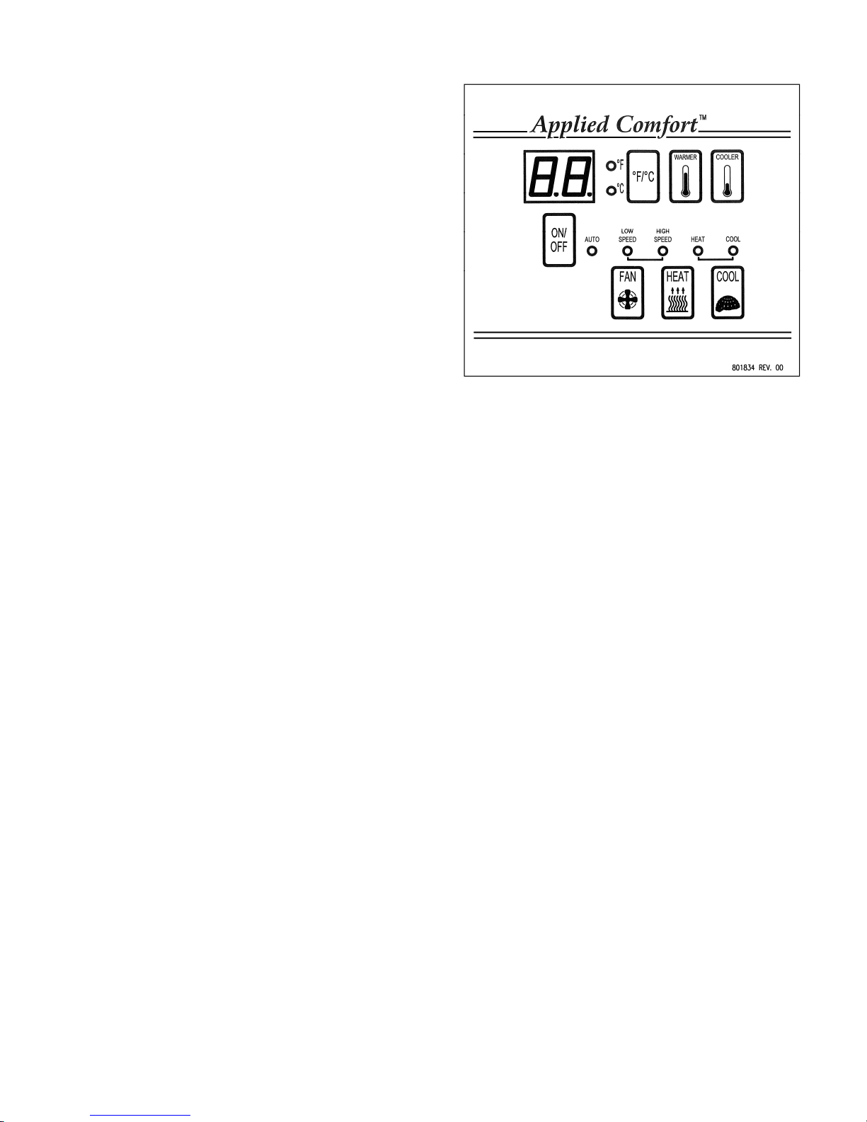
WALL THERMOSTAT OPERATION
Heat Sets the unit into heating mode.
Initiates heating when room
temperature falls below set point.
Off Disables heating and cooling
modes, but allows control of fan.
Cool Sets the unit into cooling mode.
Initiates cooling when room
temperature rises above set point.
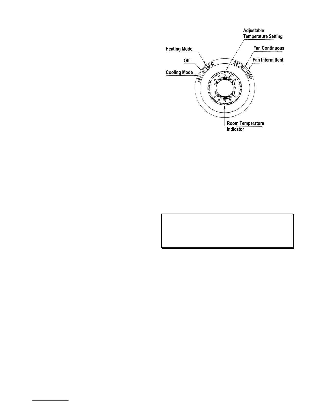
Auto
(not shown) Found on automatic changeover
thermostats only. Allows the
thermostat to decide whether it
should be in the heating or cooling
mode. Usually a 4 Fdifferential
or “deadband” will exist between
heating and cooling set points to
prevent inadvertent rapid
switching between modes.
Temperature
Setting Establishes the “set point”, or
desired room temperature.
Fan On Synonymous with “Fan
Continuous”. Fan will continue to
run after the heating and cooling
function has cycled off. Fan will
continue to run even when mode
switch is in Off position.
Fan Auto Synonymous with “Fan
Intermittent”. Fan will cycle on
and off with the heating cycle or
cooling cycle, and will not operate
between cycles.
ADDITIONAL FEATURES:
Some additional features of the Electronic Control
units are as follows:
Room Freeze Protection
This feature is enabled when the unit is shipped from
the factory. The feature can be disabled by qualified
service personnel. If power is available to the unit, and
regardless of whether it is turned ON or OFF, the unit
will automatically supply heat to the room with the fan
running at low fan speed if the room temperature falls
to 50°F (10ºC). The heat will turn off when the room
temperature reaches 55°F (13ºC). For the feature to
work, the unit must be configured with an electric
heater. The feature is enabled whether the unit is
configured for keypad or remote thermostat. The
protection remains active when the unit is OFF, for
either keypad or remote thermostat application, as long
as the unit is plugged in, power is available, and a heat
source is configured in the unit and is working.
Compressor Short-Cycle Protection
If the electronic control shuts the compressor down for
any reason, a 3 minute time delay will elapse before
the compressor is allowed to re-start. This prevents
compressor overload during re-start due to unequal
system refrigerant pressures.
Indoor Coil Freeze Protection
Control of frost on the evaporator coil due to low
indoor loads, or cold outdoor ambient temperatures, is
provided.
Low Outdoor Temperature Lock-out
If the outdoor temperature is too low for proper
compressor operation, cooling operation will be
suspended until the outdoor temperature rises to an
acceptable point, depending on the application.
Indoor Temperature Limiting (Keypad Control
Only)
Using the keypad control and display, high and low
temperature limits can be established to prevent the
user from entering set point temperatures colder or
warmer than what the property manager or hotel
operator may desire. The temperature limit choices are
as follows:
Configuration Code Low Limit °F
(ºC) High Limit °F
(ºC)
R1 63 (17) 86 (30)
R2 65 (18) 86 (30)
R3 65 (18) 90 (32)
R4 67 (19) 88 (31)
R5 67 (19) 92 (33)
R6 69 (20) 90 (32)
R7 69 (20) 72 (22)
The procedure to set the limits is as follows:
Depress the On/Off key, the °F/°C key, and the
Warmer key simultaneously for 5 seconds to enter the
limit setup mode. The Warmer and Cooler keys will
scroll through the R-values indicated in the above
table. Once the desired R-value has been obtained on
the display, press the On/Off key to accept the change,
and then press it again to effect the change and restore
the normal display.

10 803877 Rev. 00
Automatic Powered Damper
Some units may be provided with an automatic
powered fresh air damper that opens the fresh air door
to bring outdoor air into the room whenever the indoor
fan is running on high speed. If the indoor fan shuts
off, the damper automatically closes. The factory
default is fresh air with high speed fan operation only,
but it can be changed to open with low speed fan
operation only by having qualified service personnel
re-wire the unit as shown on the specific wiring
diagram affixed to the unit.
WARNING: The conversion procedure involves
exposure to high voltage electrical circuits in the
control box in order to make the necessary change to
the damper action tied to motor speed, and must be
performed by qualified service personnel. Failure to do
so could result in property damage, personal injury or
death. Disconnect electric power to the unit before
servicing.
Table of contents
Other Applied Comfort Air Conditioner manuals

Applied Comfort
Applied Comfort WM09LS User manual

Applied Comfort
Applied Comfort A26EC09L00EZA30 Quick start guide

Applied Comfort
Applied Comfort C42EC07K30E7A90 Service manual

Applied Comfort
Applied Comfort VF20HA09K36E7M90 Service manual

Applied Comfort
Applied Comfort SD User manual

Applied Comfort
Applied Comfort CALM U42 Series Quick start guide

Applied Comfort
Applied Comfort NYWC Series User manual

Applied Comfort
Applied Comfort SC Guide

Applied Comfort
Applied Comfort COOLFLOW32 User manual

Applied Comfort
Applied Comfort VF20HA09K36E7MA90 User manual