Applied Comfort SD User manual

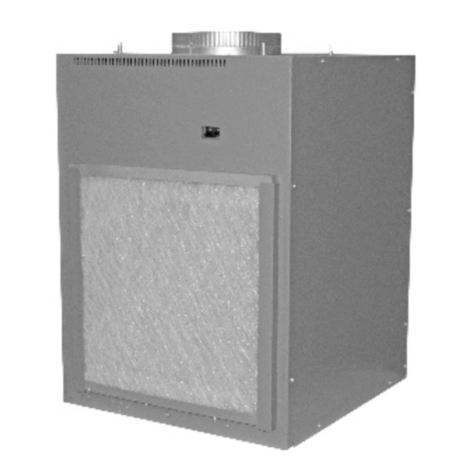
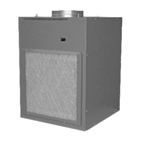
SD DOWNFLOW DUCTED PACKAGED TERMINAL AIR CONDITIONERS
Heating and Cooling Unit
Cooling - Only Unit
INSTALLATION & OPERATION MANUAL
Effective February 1985 (Revision Date: April 2009)
This manual supersedes all previous issues.
801108 REV. 01 APR 2009

1
TABLE OF CONTENTS
Page
TYPICAL ASSEMBLY DETAIL ........................................................................................................ 1
COMPONENTS................................................................................................................................. 2
INSTALLATION ................................................................................................................................ 6
Installation of the Cabinet/Wall Sleeve & Transition Cabinet......................................................... 6
Power & Control Wiring ................................................................................................................. 7
Chassis Installation........................................................................................................................ 7
OPERATING INSTRUCTIONS ......................................................................................................... 8
Control System Description ........................................................................................................... 8
OPERATING PROCEDURES........................................................................................................... 9
Suggested Operating Procedures ................................................................................................. 9
If The Unit Doesn’t Work................................................................................................................ 9
PREVENTIVE MAINTENANCE ........................................................................................................ 9
Before Each Heating and Cooling Season: ................................................................................... 9
WARNING: SAFETY HAZARD
THE SD SERIES UNITS MUST BE USED FOR DUCTED APPLICATIONS ONLY.
FREE AIR DISCHARGE APPLICATIONS REQUIRE THE SU SERIES, WHICH IS A SPECIALLY
CONFIGURED UNIT, SIMILAR IN APPEARANCE, BUT WHICH INCORPORATES A DISCHARGE
GRILLE AND OTHER SAFETY FEATURES REQUIRED FOR FREE AIR DISCHARGE APPLICATIONS.
FAILURE TO HEED THIS WARNING COULD RESULT IN PROPERTY DAMAGE, PERSONAL INJURY
OR DEATH.

2
COMPONENTS
1. Wall Sleeve & Outdoor
Grille
The wall sleeve is to be built into
the wall during construction. The
wall sleeve is used for all wall
thicknesses from 2” through 13”
maximum. For a 13” deep wall the
outdoor louvers will have to be
mounted flush with the outside wall
surface. For walls thicker than 13”,
a cabinet extension is required.
For installation of wall sleeve
extensions, see instructions
packed with the extensions.
The wall sleeve must penetrate
into the room by a fixed distance in
order for the downflow room
cabinet apparatus to function
properly. Therefore set the sleeve
in the wall so that 1” of the sleeve
protrudes into the room. This is
necessary in order to obtain the
10” distance between the front
panel and the inside wall face as
shown in Figures 1 and 2, once the
plenum and side ducts are added.
After installation of the wall sleeve,
the sleeve should be thoroughly
cleaned. The room-side portion of
the cabinet should be carefully
protected during the construction
period to prevent scratching of the
paint.
IMPORTANT:
The heating/cooling unit must not
be used for temporary heating or
cooling during the building’s
construction stage.
2. Heating/Cooling Chassis
This chassis includes all cooling
components, air moving
components and controls, except
for the 24-volt room thermostat.
3. Power Supply Cord & Plug
A power supply cord with 30 Amp
or 50 Amp male plugs (as
applicable) extends from the left
side of the control section located
on the right hand side of the unit.
This cord is to be attached to a
field – supplied receptacle
mounted in the factory – supplied
junction box mounted in the sub
base located under the unit. The
sub base is sized to fill the gap
between the finished floor and the
room cabinet when the wall sleeve
is installed 4” above the finished
floor as shown in Figure 1.
If the maximum fuse or circuit
breaker listed on the unit rating
plate is 30.0 Amps or less, then a
NEMA 6-30R receptacle is used. If
the marked maximum fuse or
circuit breaker rating exceeds 30.0
Amps, then a NEMA 6-50R
receptacle must be used. The
cover plate is supplied with the sub
base.
4. Plenum / Vertical Ducts
The plenum is a horizontal duct
that attaches by screws to the top
panel of the chassis, once the
chassis is fully inserted and drawn
up tightly in the wall sleeve. The
plenum collects the air as it exits
from the top of the chassis, and
turns the air in a right hand and left
hand direction. When the air
reaches the ends of the plenum, it
is directed downward into the
vertical side ducts where it flows
toward the floor. Air duct outlet
collars are provided on the side
ducts.
The left and right vertical side ducts
are fully insulated and connect to
the underside of the plenum using
the sheet metal screws provided.
Ensure the duct collars on the side
ducts are facing away from the
chassis so air will be directed out
the left and right sides of the room
enclosure apparatus.
5. Ducting
The vertical side ducts come
complete with a duct collar on the
lower outboard side, to accept 6”
wide by 8” high lateral flanking
duct. The unit must be ducted out
both sides. The interior of the
flanking duct must be insulated
with a minimum of ½” thick
fiberglass duct liner, suitable for the
air velocities involved. The outlet
vents should be located on the top
of the distribution ductwork facing
up.
6. Duct Sizing
The ducts must be sized for a
maximum pressure drop of 0.20” of
water column at 400 CFM total
airflow directed out both sides of
the unit. This will ensure that
adequate airflow will result when
the unit is operating at the factory –
set indoor blower speeds for the
particular heating and cooling
capacity of the unit. There is no
minimum pressure drop so large or
short ducts are not a problem.
Size the duct for the anticipated
fraction of 400 CFM pertaining to
that branch. In other words, if 40%
airflow is desired out of the left side
and 60% out the left, then size the
duct as follows:
40/100 X 400 = 160 CFM at .20”
w.c. maximum, out the right side.
60/100 X 400 = 240 CFM at .20”
w.c. maximum, out the left side.
Or, design both ducts for 240 CFM
at .2” w.c. maximum and use
dampers or the right side outlet
grilles to throttle the flow down to
160 CFM in the right side branch.
The .20” w.c. pressure drop should
also include the air resistance
through the outlet vents calculated
at the predicted CFM exiting out
each vent.
3
.

4

5
Wall Sleeve & Outdoor Grille
The wall sleeve is to be built into
the wall during construction. The
wall sleeve is used for all wall
thicknesses from 2” through 13”
maximum. For a 13” deep wall the
outdoor louvers will have to be
mounted flush with the outside wall
surface. For walls thicker than 13”,
a cabinet extension is required.
For installation of wall sleeve
extensions, see instructions
packed with the extensions.
The wall sleeve must penetrate
into the room by a fixed distance in
order for the downflow room
cabinet apparatus to function
properly. Therefore set the sleeve
in the wall so that 1” of the sleeve
protrudes into the room. This is
necessary in order to obtain the
10” distance between the front
panel and the inside wall face as
shown in Figures 1 and 2, once the
plenum and side ducts are added.
After installation of the wall sleeve,
the sleeve should be thoroughly
cleaned. The room-side portion of
the cabinet should be carefully
protected during the construction
period to prevent scratching of the
paint.
IMPORTANT!
The heating/cooling unit must not
be used for temporary heating or
cooling during the building’s
construction stage.
7. Heating/Cooling Chassis
This chassis includes all cooling
components, air moving
components and controls, except
for the 24-volt room thermostat.
8. Power Supply Cord & Plug
A power supply cord with 30 Amp
or 50 Amp male plugs (as
applicable) extends from the left
side of the control section located
on the right hand side of the unit.
This cord is to be attached to a
field – supplied receptacle
mounted in the factory – supplied
junction box mounted in the sub
base located under the unit. The
sub base is sized to fill the gap
between the finished floor and the
room cabinet when the wall sleeve
is installed 4” above the finished
floor as shown in Figure 1.
If the maximum fuse or circuit
breaker listed on the unit rating
plate is 30.0 Amps or less, then a
NEMA 6-30R receptacle is used. If
the marked maximum fuse or
circuit breaker rating exceeds 30.0
Amps, then a NEMA 6-50R
receptacle must be used. The
cover plate is supplied with the sub
base.
9. Plenum / Vertical Ducts
The plenum is a horizontal duct
that attaches by screws to the top
panel of the chassis, once the
chassis is fully inserted and drawn
up tightly in the wall sleeve. The
plenum collects the air as it exits
from the top of the chassis, and
turns the air in a right hand and left
hand direction. When the air
reaches the ends of the plenum, it
is directed downward into the
vertical side ducts where it flows
toward the floor. Air duct outlet
collars are provided on the side
ducts.
The left and right vertical side ducts
are fully insulated and connect to
the underside of the plenum using
the sheet metal screws provided.
Ensure the duct collars on the side
ducts are facing away from the
chassis so air will be directed out
the left and right sides of the room
enclosure apparatus.
10. Ducting
The vertical side ducts come
complete with a duct collar on the
lower outboard side, to accept 6”
wide by 8” high lateral flanking
duct. The unit must be ducted out
both sides. The interior of the
flanking duct must be insulated
with a minimum of ½” thick
fiberglass duct liner, suitable for the
air velocities involved. The outlet
vents should be located on the top
of the distribution ductwork facing
up.
11. Duct Sizing
The ducts must be sized for a
maximum pressure drop of 0.20” of
water column at 400 CFM total
airflow directed out both sides of
the unit. This will ensure that
adequate airflow will result when
the unit is operating at the factory –
set indoor blower speeds for the
particular heating and cooling
capacity of the unit. There is no
minimum pressure drop so large or
short ducts are not a problem.
Size the duct for the anticipated
fraction of 400 CFM pertaining to
that branch. In other words, if 40%
airflow is desired out of the left side
and 60% out the left, then size the
duct as follows:
40/100 X 400 = 160 CFM at .20”
w.c. maximum, out the right side.
60/100 X 400 = 240 CFM at .20”
w.c. maximum, out the left side.
The .20” w.c. pressure drop should
also include the air resistance
through the outlet vents calculated
at the predicted CFM exiting out
each vent.
6
INSTALLATION
INSTALLATION OF THE
CABINET AND WALL SLEEVE
1. The cabinet/wall sleeve may be
positioned in the wall to suit the
application subject to the
limitations that:
a) The finished wall must be
10” from the front of the
cabinet. See Figures 1 and 2.
b) The outdoor louver must be
flush or extending beyond the
outside wall (no recess). Use a
wall sleeve extension if
necessary. Figures 1 and 2
represent typical installations.
c) The wall sleeve must be
rigidly installed in the wall.
There are some installations
where it may be necessary to
anchor the top and sides of the
wall sleeve to the wall using
appropriate fasteners for the
type of construction.
d) For best results, the rear 12”
of the cabinet should be
supported by concrete,
regardless of wall construction.
The inside edge of the cabinet
must be 4” above the finished
floor to allow adequate space
for air flow to the unit and to
ensure proper fill by the sub
base. See Figure 1.
2. The cabinet/wall sleeve will not
support the wall above it.
Provide necessary lintels to
prevent distortion of the
cabinet.
3. The wall sleeve will be set in
wet concrete or mortar and
pressed firmly into place to get
contact between the concrete
and the bottom. Further details
follow.
IMPORTANT: The wall sleeve
must possess an overall ¼”
slope downward toward the
outside to ensure proper water
drainage. The wall sleeve must
also be level from side-to-side.
Failure to do so may cause
property damage by water
flowing into the conditioned
space.
4. All cracks or openings between
the cabinet and the wall must
be filled with mortar and/or
caulked.
5. Receptacle mounting,
installation of the junction box,
and rough wiring must be
completed at the time of wall
sleeve installation. Electrical
entrance must be between the
concrete, wall sleeve, and sub
base. Detailed instructions
follow.
A. New Masonry Wall
1. From the architect’s drawings,
determine the position of each
unit and mark the centerline of
the cabinet/wall sleeve. Also,
mark the location of the high
voltage receptacle enclosure
and the area of entrance for
the low voltage wiring. Low
voltage wiring exits through the
left side of the cord recess
located in the front face of the
sub base.
2. Run wiring to location for each
unit, as established in step 1.
3. Completely finish all concrete
work associated with floor and
wall (fig. 2 & 3).
4. Provide 12” wide concrete pad
under unit.
5. Install high voltage
wiring/conduit into the junction
box in the sub base. Leave at
least 8” of free wire inside the
conduit box to facilitate
connections.
6. Pull the low voltage wiring out
through the hole in the cord
recess area in the sub base.
7. Set the cabinet/wall sleeve in
¾” wet concrete – it must be
level from side to side, and
sloped ¼” overall, toward the
outside, for proper drainage.
Press into place.
8. Attach the sub base to the
sleeve using the three
grounding screws before the
concrete sets.
9. Ensure cabinet/wall sleeve is
not distorted during installation
and is adequately protected
during the construction period.
10. Build up wall around cabinet,
making sure that the cracks are
closed and that the cabinet
remains square, especially on
the top.
B. Existing Masonry Wall
Cut opening into wall, providing a
minimum of ½” clearance on sides
and top and 1” on the bottom, to
pour new base (12” wide).
Follow steps 4 through 10 in “New
Masonry Wall”.
C. New Panel Wall
Provide 12” wide concrete pad
under unit.
Follow steps 4 through 10 in “New
Masonry Wall”.
D. Existing Panel Wall
Cut Opening in existing wall slightly
larger than cabinet/wall sleeve. Be
sure to locate at least 4” above
finished floor.
Follow steps 4 through 10 in “New
Masonry Wall”.

7
INSTALLATION
POWER & CONTROL WIRING
1. Connect power supply for the
unit to the correct terminals of
the receptacle.
2. Install wired receptacle into
conduit enclosure. Install
receptacle cover plate provided
with the sub base.
3. A six -position low voltage
connector plug with 24” leads
is provided for 24 volt Class II
wiring connections. The
connector plugs into a mating
receptacle in the side of the
chassis control box that can be
unplugged to facilitate removal
of the chassis for servicing.
Connections between the 24”
leads and thermostat wiring
can be made outside the sub
base enclosure and in
accordance with the specific
wiring diagram affixed to the
chassis. The thermostat wire
connections can be stuffed
back through the hole in the
sub base
CAUTION: One side of the
unit’s 24-volt control system is
grounded. When wiring the
thermostat, care must be taken
not to ground the red wire,
thereby potentially burning out
the transformer.
CHASSIS INSTALLATION
1. Check all air seals in the
cabinet.
2. After all construction is
complete and the unit location
is thoroughly cleaned, the heat
cool chassis is ready for
installation in the cabinet/wall
sleeve.
3. Unpack heat/cool chassis from
shipping carton. Check for any
shipping damage.
4. Position the chassis in the
cabinet and slide into place.
Keep the chassis level and
square to prevent binding. The
chassis must be pushed into
the cabinet until the draw bolts
screws in the chassis side
panels can engage the
threaded clip in the sleeve.
Alternate turning the two draw
bolts until the chassis is drawn
snugly into the sleeve. Do not
over-tighten the draw bolts.
NOTE:
When handling the chassis,
care must be taken to ensure
that no damage occurs to the
fan wheels. Damaged or
unbalanced fans will cause
excessive noise and will impair
unit performance.
5. Position the plenum and
vertical side duct assembly
over the chassis. While
pushing the plenum assembly
against the inside wall, line up
the plenum slots with the panel
holes and screw the parts
together.
6. Screw the plenum top cover on
to the plenum.
7. Install the ducting to the side
duct flanges as described in
the previous section entitled
“Ducting”.
8. Connect low voltage wiring
harness to the heat/cool
chassis.
9. Plug the heat/cool chassis cord
into the power receptacle in the
sub base.
10. Install the unit air filter into
position.
NOTE: Ensure that the cord is
pushed well into the cord
recess of the sub base or the
filter will not be able to be
completely inserted.
11. Install front panel.
12. Wipe unit cabinet/wall sleeve to
remove dirt, etc.
13. The unit is now ready for
operation, when supplied with
power from the distribution
panel and when wired to a
thermostat.

8
OPERATING INSTRUCTIONS
The Unitary Package Heating,
Cooling Unit has been carefully
designed and built to provide
reliable operating performance
when installed and maintained
correctly.
CONTROL SYSTEM
DESCRIPTION
The unit is controlled on both
heating and cooling by a low
voltage wall mounted thermostat.
Any standard 24-volt heat/cool
thermostat intended to control a
gas-heating unit with cooling can
be made to work with the unit.
A room thermostat is basically a
switch used to direct 24 volt power
from the “R” terminal to its W, Y,
and G terminals, according to the
function being demanded by the
user. Sometimes an electronic
thermostat needs to be powered
with 24 volts via connection to an
additional “C” or “Common”
terminal, typically if its display is
backlit. If the thermostat demands
that the “C” connection be made at
the thermostat wiring terminals,
then please order the additional
black lead that will insert into the
unit’s low voltage connector, Part
No. 18BK23Y-024.
Heating and cooling will be cycled
on, as dictated by the setting of the
wall thermostat. In this mode, the
room-side fan will run at factory-
predetermined speeds for heating
and cooling.
IMPORTANT: The factory-set
indoor fan speeds must not be
changed. The product safety
certification relies on fan speeds
being coordinated with specific
heater sizes.
The indoor fan will be off when
neither heating nor cooling are
required, if the fan switch on the
thermostat is set to “AUTO”. If the
fan switch is set to “ON”, the indoor
fan will circulate air continuously on
low speed, until there is a call for
heating or cooling.
To get reasonable comfort and
energy consumption, it is
recommended that wall mounted
thermostats be set at 21°C (70°F)
for heating and 25°C (77°F) for
cooling.
Over-adjusting the thermostat will
not increase the rate at which a
unit will heat or cool the space; it is
merely an on-off switch that
responds to temperature.
ATTENTION: Do not place the wall
thermostat in locations where it
cannot detect true room
temperature, such as in direct
sunlight or near air registers. Also
beware of drafts flowing through
the thermostat wiring hole.

9
OPERATING PROCEDURES
SUGGESTED OPERATING
PROCEDURES
To obtain the maximum comfort
from your packaged heating and
cooling unit, the following
procedures are recommended.
1. Always draw drapes or blinds
in the summer, to block out
direct rays from the sun.
2. Keep windows and doors
closed when operating unit on
cooling.
3. Prior to operating unit on
cooling, ensure filter is clean
for maximum efficiency.
4. Check filters regularly. Filters
have to be cleaned in
accordance with the unit
environment. Never operate
unit with a dirty filter or without
a filter.
5. Ensure that the air discharge
and return air openings are not
obstructed, causing a restricted
air flow condition. DO NOT
PLACE ARTICLES ON
DISCHARGE REGISTERS.
6. When adjusting the thermostat,
be careful not to over control.
A change in temperature of
plus or minus 2 degrees can
make the difference between
comfort and discomfort. Set the
control at the recommended
comfort settings and allow the
unit to operate at that setting.
The unit will automatically
maintain the comfort level by
cycling on and off as required.
IF THE UNIT DOESN’T WORK
The unit has been carefully
designed and tested and should
provide trouble free operation
when properly sized, correctly
installed, intelligently operated and
checked by a competent
serviceman at least once a year.
However, if you should experience
difficulty, check the following before
calling for services.
1. Ensure that controls are
properly set.
2. Check to see if a fuse has
blown or a breaker has tripped.
3. Check to see that the power
plug is properly engaged.
4. If unit is calling for cooling,
check to see if outside
condenser fan is running.
5. Is cooling being demanded at a
very low outdoor temperature?
The unit is designed to
discontinue cooling operation
at low outdoor temperatures
where air conditioning is not
typically required.
If, after checking the above, your
unit is still not operating, call in
competent service personnel.
ATTENTION: When in cooling
mode, if the compressor is shut off
by switching from cooling to
heating with the heat/cool switch,
then wait 3 minutes before re-
starting. The same applies for a
power interruption.
PREVENTIVE MAINTENANCE
WARNING:
DISCONNECT POWER SUPPLY
TO UNIT BEFORE REMOVING
FRONT PANEL.
Before each heating and
cooling season:
1. Remove front panel and
disconnect control wiring.
2. Clean front surfaces with
vacuum cleaner and damp
cloth.
3. Remove the plenum cover to
access the plenum-to-chassis
mounting screws – remove the
screws.
4. Loosen the draw bolts that are
affixed to the chassis side
panels.
5. Pull the chassis out of the
sleeve, and set on a stable
surface.
6. Remove condenser cover and
clean the condenser with a
bristle brush and vacuum
cleaner.
7. With condenser cover
removed, reach down into the
primary drain pan, at the
bottom of the coil, and clean
the pan, as well as the
condensate drain tube. Be
sure the tube is clear.
8. Clean fan wheels with a soft
brush. Caution must be used to
avoid bending blades.
9. The motors are permanently
lubricated and need no re-
oiling. Inspect electrical wiring
and repair if necessary.
10. Check all sealing gaskets and
repair if necessary.
11. Reinstall heating/cooling
chassis. Reinstall control
wiring. Reinstall grounding
screws.
12. Replace front panel and
reinsert plug.
13. Turn power on and test unit for
proper heating and cooling.
Table of contents
Other Applied Comfort Air Conditioner manuals

Applied Comfort
Applied Comfort CALM U42 Series Quick start guide

Applied Comfort
Applied Comfort WM09LS User manual

Applied Comfort
Applied Comfort VF20HA09K36E7MA90 User manual

Applied Comfort
Applied Comfort A26EC09L00EZA30 Quick start guide

Applied Comfort
Applied Comfort C42EC07K30E7A90 Service manual

Applied Comfort
Applied Comfort NYWC Series User manual

Applied Comfort
Applied Comfort SCA Owner's manual

Applied Comfort
Applied Comfort CDF Service manual

Applied Comfort
Applied Comfort VF20HA09K36E7M90 Service manual

Applied Comfort
Applied Comfort SC Guide