Applied Comfort SC Guide

INSTALLATION
OPERATION
S-SERIES
ELECTRIC COOLING/HEATING
AND HEAT PUMP
PACKAGED TERMINAL
AIR CONDITIONERS
1090653 REV. 03 REF ECN06028

General Information
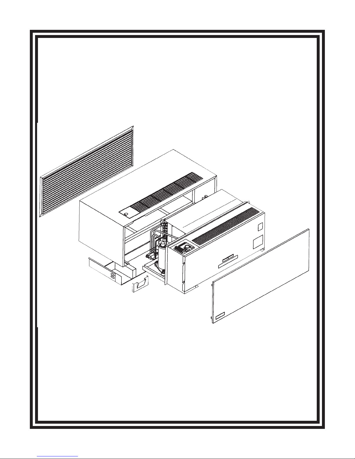
DO NOT INSTALL CHASSIS INTO SLEEVE WITHOUT FIRST
READING CHASSIS INSTALLATION PROCEDURE.
RECOMMENDATIONS FOR
EFFICIENT OPERATION
·
·
Keep air intake filter clean. Units are provided with a
washable filter that can be cleaned with soap and water
(we recommend monthly). IMPROPERLY
MAINTAINED FILTER OR NOT USING A FILTER WILL
VOID COMPRESSOR WARRANTY.
Don’t block off the outside air flow to the unit. Paper or
other material on the outside of the unit can impair
efficiency and cause serious damage to the compressor.
·
·
·
When unit has been turned OFF, wait three minutes
before re-energizing unit.
In case of power interruption, it is recommended that
the unit be turned “OFF” until power has been restored
for three minutes. (Operation of the air conditioner with
low voltage input can cause serious damage.)
Clean unit coil and oil motors annually. Some motors
are permanently lubricated and do not require annual
oiling.
To avoid property damage, bodily injury or death, ensure power is disconnected before any service is attempted.
Repairs should be made by a qualified air conditioner service technician only.
DANGER
UNIT OPERATION
(For Units Equipped with Heating Option)
THERMOSTAT OPERATION WHEN STARTING:
Set the dial in the mid position to begin operation. After
several hours of operation adjust to desired comfort
setting. No further adjustment is necessary. Your unit
will bring the room back to the desired temperature each
time you turn the unit on.
ADJUSTING DURING OPERATION:
Move the dial a small amount at a time in the direction
you wish the temperature to go. Moving the dial more
than 1/8 inch at a time may overcompensate and lead to
an extreme hot or cold situation.
EMERGENCY HEAT OPERATION
(Heat Pump Units Only)
In the unlikely event of a compressor failure, the electric
heater can be manually energized.
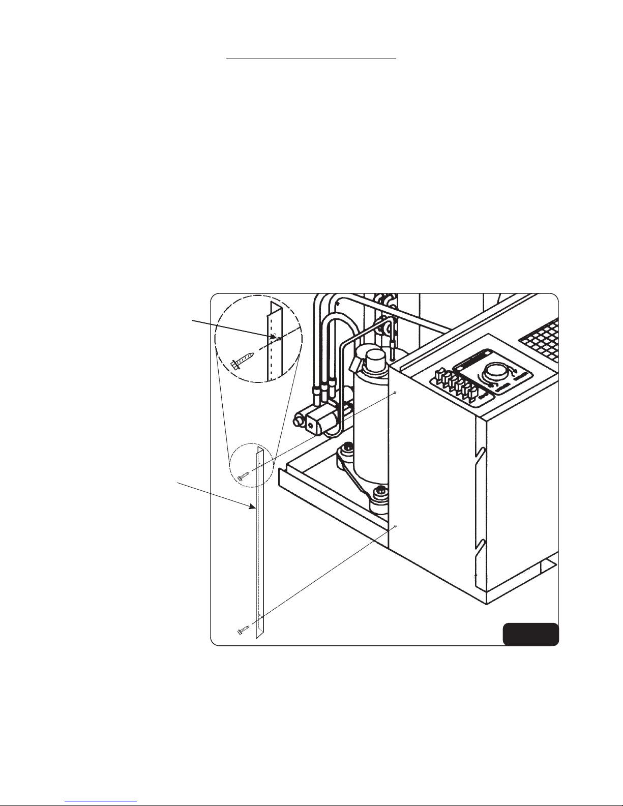
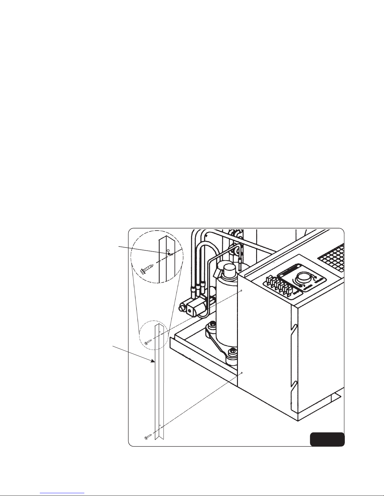
By removing the front panel of sleeve cabinet, you will
find a manual emergency heat switch located on the
lower left side of the chassis in the excess cable storage
area. The switch is marked and
. By moving the switch to
the resistance heat will come on providing the
push-button switch is in the mode. See Figure
12, page 10.
The temperature is controlled through the thermostat.
Remember to turn switch to when the unit
has been repaired.
“EMERGENCY HEAT”
“NORMAL” “EMERGENCY
HEAT”
“HEAT”
“NORMAL”
UNITS WITH LOW TEMPERATURE
THERMOSTAT
Some units may be equipped with a low temperature
thermostat.
This option energizes the fan and electric heater
whenever the room temperature approaches freezing
conditions, regardless of the push-button switch setting.
GENERAL
Temperature control is automatic once you have
selected desired mode of heat or cool and the
temperature you wish to maintain in the room. No further
adjustments are necessary for your comfort control.
The heat pump heating cycle will automatically switch
from heat pump mode to electric resistance heat when
outdoor ambient temperature drops below the design
temperature of the unit.
The buttons on the control panel determine the mode
(heat or cool) and the thermostat pointer on the control
panel determines the room temperature.
2

PUSH-BUTTON OPERATION
Depress these buttons for the following effect:
Entirely stops system as well as closes vent (if open). If
you wish to resume cooling or heating, wait at least 3
minutes before re-starting.
Starts the air conditioning system on cooling. Cooling
will not begin if room temperature is below 60ºF (16ºC).
Starts the unit on heating.
A heat pump, unlike an electric or gas furnace, will not
supply extremely hot air from the discharge grille.
Depending on the outside temperature the air leaving
the grilles will vary. Any air temperature below 102ºF
(49ºC) will feel cool to the human body. This does not
mean the system is not working properly.
OFF
COOL
HEAT
HIGH
LOW
VENT ON
VENT OFF
Activates indoor and outdoor motors on high speed
independently of “heat” or “cool” mode for maximum
effect.
Allows outside air to enter the room. The vent door
closes automatically when “OFF” button is depressed.
Cooling or heating is more efficient when vent is closed.
Open vent when fresh air is desired.
Closes vent door while unit is in operation.
Activates indoor and outdoor motors on low speed
independently of “heat” or “cool” mode for minimum
sound level.
TEMPERATURE LIMITING
THERMOSTAT (If Equipped)
Remove the thermostat knob and observe its plastic rib
directly under the RED indicator line. Also observe the
eight holes in the dial plate surrounding the thermostat
stem. Refer to Figure 1 showing letters “A” through “H”
identifying these holes for future reference. There
should be two screws located in holes “A” and “H”. The
approximate temperature range (with screws in these
positions) is 64º to 89ºF (18º to 32ºC). Each hole
represents approximately 3 1/2º F (2ºC) change from
adjacent hole.
In Order to set the temperature range, move screws to
desired location.
Replace thermostat knob so the RED indicator line is
between the two screws.
EXAMPLE: It is desired to limit the temperature range
from 71º to 81ºF (22º to 27ºC). Relocate the two screws
in the holes “C” and “F” and replace the thermostat knob
so the RED indicator line is between the two screws.
FIG. 1
3

GOOD AIR CONDITIONING PRACTICES
FILTERS
A dirty, clogged filter reduces the efficiency of the
system. It can also cause erratic performance of
controls and can result in damage to the motor, heating
element and compressor.
NOTE
Do not operate the unit with front panel removed, or
without filter installed.
Inspect and clean the filter a least once a month or more
often as conditions dictate. Replace as necessary.
Improperly maintained filter or not using a filter will void
warranty.
INDOOR/OUTDOOR COILS
Efficient operation of unit depends on free circulation of
air over the indoor and outdoor coils.
DO NOT:
·
·
·
·
Stack anything against the indoor or outdoor sections.
Drape anything against the indoor or outdoor sections.
Allow furniture, draperies, curtains, etc. to block the free
flow of air.
Plant flowers, vines or shrubbery too near the unit.
DIRTY COILS/BENT FINS
Periodically inspect the indoor and outdoor coils for
build-up of lint, dust, leaves, foreign debris, etc., and
bent fins.
Clean the coils using a brush and compressed air.
CAUTION
Do not use sharp objects to clean coils or you may
puncture the refrigerant tubing.
SNOW AND ICE
In areas of heavy snow and ice accumulation, snow and
ice should not be permitted to accumulate against the
unit.
As soon as practical after such inclement weather, clear
snow and ice from around the unit and as much as
possible from the grilles on the unit.
Keep doors and windows closed.
Leaving doors and windows open will increase the
workload on the air conditioner or heat pump. This
results in higher operating costs.
FIG. 2
Subbase with electrical receptacle.
It is the personal responsibility of the customer to
retain an electrician who will make sure that all
electrical connections and wiring are in
conformance with the latest edition of the National
Electrical Code and/or Local Codes having
jurisdiction.
WARNING
ELECTRICAL
ELECTRICAL WIRING &
NECESSARY WIRE SIZE FOR
RECEPTACLE
Use necessary wire size and receptacle to match unit
plug and minimum circuit ampacity as stated on the
rating plate of the unit.
A single outlet branch circuit from main fuse box to
receptacle at unit should be used. Wire size must also
take into account any distance from fuse box to
receptacle to prevent voltage drops in undersized wires.
Low unit voltage will cause compressor starting
problems and decrease the performance and reliability
of the compressor.
A subbase kit (Fig. 2) is necessary for
permanently connected 208/230 or 277 volt
installations.
CAUTION:
4

FIG. 3 FIG. 4
RECEPTACLE
Receptacle must match plug on unit service cord.
DO NOT:
·
·
·
Change length of service cord.
Bend /alter or change service cord plug configuration.
Use extension cords.
To avoid property damage, bodily injury or death, the
unit must be used on a grounded power supply only.
WARNING
Unit is grounded through service cord plug and matching
receptacle when branch circuit is grounded.
UNITS WITHOUT SUBBASE
For units without a subbase, and to help keep the cord
and receptacle out of sight, the electrical receptacle
should be located directly below chassis (See Fig. 3).
FUSE/CIRCUIT BREAKER
Use type and size fuse as indicated on the rating plate; or
HACR type circuit breaker as indicated on the rating
plate of the unit.
SLEEVE CABINET
Sleeve cabinet installation instructions are included with
the sleeve in its carton.
5

Use hole closest
to flange.
Flange facing
front of unit.
CHASSIS FLANGE INSTALLATION
(Standard Position)
This position will be used in the majority of sleeves
currently installed to date.
The flange is located 8 inches from the front of the
chassis.
If old unit is not available, install the left side flange as
described and continue on with “Chassis Installation”, if
the chassis will not fit properly, try “Optional Position ”A”
or “B” described on the following pages.
If unit being replaced is still available, measure distance
from the front of chassis to flange, to determine the
correct position.
CHASSIS INSTALLATION
Unit is shipped from the manufacturer with the top and
right chassis flange in place.
Install the left side chassis flange using the following
steps:
1. Remove the two screws from the left side of unit where
flange would normally be located.
2. Position chassis flange so the flange is facing the front
of the unit as illustrated in Figure 5.
3. Using the larger set of holes located closet to the
flange end, fasten with screws removed from side of unit
in step “1”.
6
FIG. 5

Use hole closest
to flange.
Flange facing
back of unit.
CHASSIS FLANGE INSTALLATION
(Optional Position “A”)
This position will be used in a small number of sleeves
currently installed to date.
The flange is located 8 5/8 inches from the front of the
chassis.
If old unit is not available, install the left side flange as
described and continue on with “Chassis Installation”, if
the chassis will not fit properly, try “Optional Position “B”
described on the following page.
If unit being replaced is still available, measure distance
from the front of chassis to flange, to determine the
correct position.
Unit is shipped from the manufacturer with the top and
right chassis flange in place.
Install the left side chassis flange using the following
steps:
1. Remove the two screws from the left side of unit where
flange would normally be located.
2. Position chassis flange so the flange is facing the back
of the unit as illustrated in Figure 6.
3. Using the larger set of holes located closet to the
flange end, fasten with screws removed from side of unit
in step “1”.
4. Remove screws holding top and right side chassis
flanges, reverse them to match left side flange and
reattach them to unit.
7
FIG. 6

Use hole closest
to edge.
Flange facing
back of unit.
CHASSIS FLANGE INSTALLATION
(Optional Position “B”)
This position will be used in a small number of sleeves
currently installed to date.
The flange is located 9 inches from the front of the
chassis.
Unit is shipped from the manufacturer with the top and
right chassis flange in place.
Install the left side chassis flange using the following
steps:
1. Remove the two screws from the left side of unit where
flange would normally be located.
2. Position chassis flange so the flange is facing the back
of the unit as illustrated in Figure 7.
3. Using the smaller set of holes located furthest from the
flange end, fasten with screws removed from side of unit
in step “1”.
4. Remove screws holding top and right side chassis
flanges, reverse them to match left side flange and
reattach them to unit.
8
FIG. 7

9
TEMPERATURE CONTROL KNOB
The temperature control knob must be removed before
installing chassis into sleeve to gain clearance between
sleeve and chassis (See Fig. 8).
9
Carefully push chassis into sleeve until chassis flange,
(with seal) contacts the flange in the sleeve. (See Fig. 9).
All 3 chassis flanges must be installed in their proper
orientation.
Press on the chassis to make sure seal is in good contact
with sleeve surface.
FIG. 9
FIG. 8
LINE CORD
Plug in line cord to previously installed receptacle, on the
wall or within a subbase.
Fold excess line cord into area between sleeve and
chassis.
FIG. 10
INSTALLING CHASSIS
Center chassis in the sleeve and insert into pre-installed
sleeve.
CAUTION
Be very careful when installing chassis into sleeve to
prevent damage to controls.

FILTER
Apermanent type filter is supplied with unit.
Remove sleeve front panel and install filter horizontally
on rails provided.
Replace sleeve front panel (See Fig. 11).
FRONT PANEL
Install front panel making sure locking brackets are
inserted into all four slots in sleeve.
FIG. 11
Continuous or Intermittent Fan Operation
Note: Please read these instructions completely before attempting to operate the unit.
When unit is equipped with a continuous/intermittent fan feature, please note the following. The toggle switch is
located on the left hand side of the unit and is marked as such. This switch is used to switch between continuous and
intermittent fan operation.
With the toggle switch in the position, as indicated by the label next to the switch, the indoor fan will
continue to operate as long as the unit is switched on in either the heating or cooling mode. The fan will operate
continuously at the fan speed selected.
With the toggle switch in the position, and the unit in cooling mode, the indoor fan will operate only
when there is a call for cooling by the adjustable thermostat. Similarly with the unit in heating mode, the indoor fan will
operate only when there is a call for heating in order to satisfy the heat setting on the adjustable thermostat.
The effective indoor temperature sensing and highest comfort levels are achieved when the room air is being drawn
continuously across the sensing bulb of the thermostat.
The most effective indoor temperature sensing and highest comfort levels are achieved when room air is being drawn
continuously across the sensing bulb of the unit thermostat.
“Continuous”
“Intermittent”
If complaints of large temperature swings in the room
are experienced, then switch the unit to continuous fan operation.
10
FIG. 12

START-UP CHECKLIST
Note: These units should be installed and checked for proper function by qualified service personnel only.
1. Circuit breakers, wire size, all connections tight and correct
2. Condensate drain adequate (size-pitch-trapped)
3. Filter clean and in place
4. Condenser air inlet and outlet free of obstructions and short circuiting
5. Operate unit 20 minutes
6. Controls operation OK
7. Unit installed in compliance with all codes and ordinances
8.All panels in place
9. Work area clean and free of debris
10. Owner or operator instructed on control operation and routine maintenance
11. Name and phone number of service company attached to unit or noted in telephone directory
11

12
This manual suits for next models
3
Table of contents
Other Applied Comfort Air Conditioner manuals

Applied Comfort
Applied Comfort COOLFLOW32 User manual

Applied Comfort
Applied Comfort NYWC Series User manual

Applied Comfort
Applied Comfort CDF Service manual

Applied Comfort
Applied Comfort CALM U42 Series Quick start guide

Applied Comfort
Applied Comfort SCA Owner's manual

Applied Comfort
Applied Comfort A26EC09L00EZA30 Quick start guide

Applied Comfort
Applied Comfort C42EC07K30E7A90 Service manual

Applied Comfort
Applied Comfort NAEC SERIES User manual

Applied Comfort
Applied Comfort WM09LS User manual

Applied Comfort
Applied Comfort VF20HA09K36E7M90 Service manual