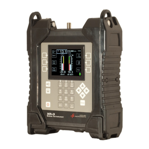
Applied Instruments XR-3 User manual

XR-3 Cable Air Module Operation Manual XR-3
Page 2 of 55
1.INTRODUCTION TO XR-3’S CABLE AIR MODULE .................................................................. 4
STANDARD ACCESSORIES............................................................................................................................ 5
2.RUN SCREEN ...................................................................................................................................... 5
SOFT KEYS .................................................................................................................................................. 7
3.MAIN MENU........................................................................................................................................ 8
4.CHANNEL PLANS .............................................................................................................................. 8
STANDARD CABLE PLANS ........................................................................................................................... 9
STANDARD OFF-AIR PLANS ...................................................................................................................... 10
CUSTOM PLANS......................................................................................................................................... 10
6.LIMITS................................................................................................................................................ 13
7.CHANNEL SCAN .............................................................................................................................. 16
COLLECT TEST DATA ................................................................................................................................ 16
FAVORITES /TILT CHANNELS.................................................................................................................... 20
SAVING DATA ........................................................................................................................................... 22
TRANSFER DATA FILE TO PC .................................................................................................................... 25
INSTALL PC SOFTWARE ............................................................................................................................ 25
ERASING FILES .......................................................................................................................................... 26
PRINT REPORTS ......................................................................................................................................... 26
8.FAVORITES GRAPH / FAVORITES SCAN ................................................................................. 29
TABLE VIEW ............................................................................................................................................. 30
SUMMARY ................................................................................................................................................. 31
SAVING ..................................................................................................................................................... 32
TRANSFER DATA FILE TO PC .................................................................................................................... 32
9.SPECTRUM SCREEN....................................................................................................................... 34
10.CONSTELLATION SCREEN ...................................................................................................... 41
11.VOLTAGE / CURRENT ............................................................................................................... 44
SOFT KEYS ................................................................................................................................................ 44
12.FILE UTILITY............................................................................................................................... 45
13.OPTIONS ........................................................................................................................................ 47
LEVEL ....................................................................................................................................................... 47
SOUNDER .................................................................................................................................................. 47
SHUTDOWN TIMER .................................................................................................................................... 47
14.VERSIONS...................................................................................................................................... 48
15.POWER........................................................................................................................................... 50
LNA POWER ............................................................................................................................................. 50
BATTERY CHARGE .................................................................................................................................... 50
AC POWER ................................................................................................................................................ 51
DC POWER ................................................................................................................................................ 51
16.TROUBLESHOOTING / FAQS ................................................................................................... 51
17.XR-3 REPLACEMENT PARTS & ACCESSORIES.................................................................. 53
18.MAINTENANCE AND REPAIRS ............................................................................................... 53
19.SPECIFICATIONS ........................................................................................................................ 54
TESCOM USA
TESCOMUSA.COM

XR-3XR-3 Cable Air Module Operation Manual
Page 3 of 55
TESCOM USA
TESCOMUSA.COM

XR-3 Cable Air Module Operation Manual XR-3
Page 4 of 55
1. Introduction to XR-3’s Cable Air Module
The XR-3 Cable Air module is used with the XR-3 modular test instrument base unit. The XR-3
Cable Air module is a signal level meter and analyzer for cable and terrestrial over-the-air
broadcast TV installation and troubleshooting. It is ideal for CATV and UHF off-air antenna
installers and private cable operators that need fast, easy signal measurements.
GENERAL FEATURES
• Works with the XR-3 Modular Test Instrument
• Friendly user interface
• Tune by frequency or tune by channel number
• Field replaceable type F-female barrel connector
• Fast system boot-up time
• Compatible with digital and analog signals
• Store measurements for Proof-of-Performance
• Programmable Pass/Fail limit scan for all channels
• Quick scan of all channels
• Easily create new custom channel plans or use standard base plans
• Spectrum Screen (frequency on x-axis, amplitude on y-axis)
• Constellation Screen (I and Q demodulator values)
VHF / UHF OFF-AIR FEATURES
• Supplies Pre-Amp / LNA power
• Simultaneously displays signal level and quality of multiple channels
• Displays measurements for analog and digital signals
• High signal sensitivity assures Off-Air antenna alignment optimization
• Manually tunes to custom channels
• Audible tone for signal lock and peak
CATV FEATURES
• Compatible with analog and digital CATV signals
• Frequency range from 5 MHz to 1 GHz
• Tilt measurement
XR-3 base unit
XR-CA-01
tuner module
TESCOM USA
TESCOMUSA.COM

XR-3 Cable Air Module Operation Manual XR-3
Page 5 of 55
MMDS FEATURES
• Powers frequency block down-converters
MEASUREMENTS
• Digital and Analog Signal Level (dBm, dBmV, or dBμV) with present and peak bar graph
• Analog Signal Quality (C/N)
• Digital Signal Quality (MER & BER)
• Locks on 8VSB (ATSC A/53) UHF digital Off-Air signals
• Locks on 64QAM and 256QAM (ITU-T J.83, Annex B) CATV signals
• Tilt
• Analog Video and Audio Carrier Measurements (NTSC, PAL, SECAM)
• Current draw of off-air antenna pre-amp / LNA
Standard Accessories
Accessories included with your XR-CA-01 Cable Air module include:
• Quick Start Guide
2. Run Screen
The Run Screen displays valuable information used to test a cable network or to point an off-air
antenna.
4
1
2
5
8
3
7
9
6
TESCOM USA
TESCOMUSA.COM

XR-3 Cable Air Module Operation Manual XR-3
Page 6 of 55
Main Run Screen Fields
1) Name of active channel plan
2) Channel number – When in Tune by Channel mode (chosen via top right Ch/Freq soft-
key), use up or right arrow keys to toggle to next highest channel in active channel plan.
Use down or left arrow keys to toggle to next lowest channel in active channel plan. To
direct-tune to a particular channel, use numeric keypad to type desired channel number
to tune to and then press Enter button.
3) Channel frequency – When in tune by channel mode, field displays frequency related to
selected channel. When in Tune by Frequency mode (chosen via top right Ch/Freq soft-
key), the up or right arrow key toggles to the next highest available frequency (0.125 MHz
increments) in the active channel plan. The down or left arrow key toggles to the next
lowest available frequency (0.125 MHz increments) in the active channel plan. To direct-
tune to a particular frequency, use numeric keypad to type desired frequency to tune to
and then press Enter button.
4) Signal type – 8VSB, QAM64, QAM256, or Analog (NTSC, PAL, SECAM)
5) Channel label (network, i.e. ESPN or station identifier, i.e. WRTV) – to be entered by you
by editing Channel Parameters
6) Lock status indicator (for digital channels)
a. Empty white space is shown when searching for a matching signal
b. Padlock icon is displayed when signal lock is obtained
7) Battery level icon
8) Signal Quality (MER or C/N)
a. Right bar graph (with peak hold center line)
b. MER (for digital channels) or C/N (for analog channels), in dB
c. Scale: 0 to >40 dB MER
9) RF Signal Level (dBm, dBmV, or dBµV)
a. Left bar graph (with peak hold center line)
b. Numeric value in dBm, dBmV, or dBµV
c. Scale: default scale is -30 to +10 dBmV
Note: Entire amplitude range -40 to +60 dBmV (-89 to +11 dBm) (+20 to +120
dBμV) is not shown on scale by default, but will auto-scale when appropriate,
according to level measured
TESCOM USA
TESCOMUSA.COM

XR-3 Cable Air Module Operation Manual XR-3
Page 7 of 55
Soft Keys
1) Spectrum screen shortcut soft-key
2) Channel Scan shortcut soft-key
3) Favorites Graph shortcut soft-key
4) Channel Number / Frequency toggle soft-key – toggles between tune-by-channel and
tune-by-frequency modes. Active mode is indicated by gray rectangle shown around the
channel field or frequency field.
5) Constellation / BER shortcut soft-key
6) Main Menu shortcut soft-key
1
2
3
4
6
5
TESCOM USA
TESCOMUSA.COM

XR-3 Cable Air Module Operation Manual XR-3
Page 8 of 55
3. Main Menu
Pressing the MENU soft-key on the main Run screen takes you to a menu of all of the XR-3
screens. Some of these screens are also available via shortcut soft-keys from the Run Screen.
You can navigate the Main Menu using the up/down and Enter keys. Some functions are also
available via soft-keys as a shortcut. “Exit” takes you back to the Run Screen.
The functions are described in the sections that follow.
4. Channel Plans
From the Run screen, press ‘Menu’ soft-key, then select ‘Channel Plans’ from the Main Menu to
reach the Channel Plans screen. Select a channel plan corresponding to the type of channels in
the system you are testing. This step is essential since the XR-3 only tunes to relevant channel
numbers and their frequencies and signal types based on this information.
TESCOM USA
TESCOMUSA.COM

XR-3 Cable Air Module Operation Manual XR-3
Page 9 of 55
This screen is a simple menu selection. To select and activate a plan, use the up/down arrow
buttons to highlight the selection you want to use and press ENTER. To create a new custom
channel plan, highlight a standard plan to be used as the base plan and press the Edit/Create
soft-key. See more details below in the Custom Plans section about how to create custom
channel plans. To edit a custom channel plan, select an existing custom channel plan and press
the Edit/Create soft-key.
Due to the large variety of systems in use, the Channel Plans selection is divided into three
sections:
1) Standard Cable Plans
2) Standard Off-Air Plans
3) Custom Plans
Standard Cable Plans
When the unit is shipped from the factory, it will have the most common compatible cable channel
plans for North America loaded:
EIASTD – This plan is designed for and automatically detects North American EIA analog
(NTSC) & digital (QAM64 or QAM256) signals from 55.25 MHz to 997.25 MHz (analog)
or 57.00 MHz to 999.00 MHz (digital).
HRC
IRC
PAL BG
PAL I
SECAM
TESCOM USA
TESCOMUSA.COM

XR-3 Cable Air Module Operation Manual XR-3
Page 10 of 55
Standard Off-Air Plans
When the unit is shipped from the factory, it will have the most common compatible off-air
channel plans for North America loaded:
NTSC ATSC – This plan is designed for and automatically detects North American
analog (NTSC) & digital (8VSB) signals from 55.25 MHz to 747.25 MHz (analog) or 57.00
MHz to 749.00 MHz (digital).
FM N. Am – This plan tunes to the 100 analog FM carrier frequencies from 88.100 MHz
to 107.900 MHz.
Custom Plans
Create a Custom Channel Plan
There are 3 ways that you can create a custom channel plan:
1) Use the Channel Scan feature and then from the Save menu, select “Save Found
Channels as new Plan”.
This method is desirable if you’re at a site and want to find which channels are present on
the existing cable or off-air system. After selecting the appropriate base Standard Cable
or Standard Off-Air channel plan, connect the meter to a coax cable and run a Channel
Scan. The meter will automatically find the active channels and determine if they are
analog or digital and will save the channel plan with the signal type detected.
2) Manually edit all of the desired channel numbers and frequencies using the meter. In the
Channel Plans section of the Main Menu, highlight a Standard Cable or Standard Off-Air
plan to be used as the base plan and press the Edit/Create soft-key. This allows you to
save the standard channel plan lineup under a different file name (Save As) so that the
new custom plan can be edited. This method is desirable if you just want to slightly
modify the channel lineup from the way it is in the Standard Plan.
Or highlight a custom channel plan in the Custom Plans section and press the
Edit/Create soft-key to edit the channel lineup and individual channel parameters. You
can change the filename, if desired (Save As), to create a new custom channel plan from
an existing custom plan.
3) Use the MeterMaid application on a PC to load a custom channel plan (.pln) file after
editing the plan file using a text editor (i.e. Notepad or Notepad++)
Create Custom Channel Plan by Scanning Channels Present On Active System
1) Connect the XR-3 to an off-air antenna (that is already aligned) or to your cable system
and detect your channels to create a custom channel plan
a. Press Menu soft-key to enter the Main Menu
b. Select ‘Channel Plans’ and press Enter.
c. Highlight the desired channel plan to use as your base plan and then press
Enter.
d. If you haven’t already, connect a coax cable from the cable system or off-air
antenna’s output to input port of XR-3’s Cable Air module.
e. While on the main Run screen where your bar graphs are, press the ‘Chan Scan’
soft-key to initiate a channel scan. The meter will sound an audible tone (beep)
when the scan is complete.
f. If you wish to pick favorite channels and tilt channels, highlight the desired
channel using the up/down arrow buttons and then press the Fav/Tilt soft-key
(by pressing the #1 button on the alphanumeric keypad that corresponds to that
soft-key). Press soft-key once to flag the channel as one of your favorites. Press
TESCOM USA
TESCOMUSA.COM

XR-3 Cable Air Module Operation Manual XR-3
Page 11 of 55
soft-key a 2nd time to flag channel as one of your tilt channels. Press soft-key a
3rd time to remove the flags. You may pick up to 5 favorite channels per channel
plan. The 2 tilt channels count as favorite channels as well.
Choosing favorite channels in an off-air plan can be very useful since you’ll then
be able to view all 5 favorite channels on the screen at once (in the Favs Graph)
while aligning the off-air antenna. Since off-air antenna alignment sometimes
ends up being a compromise because some transmitter towers are located in
one direction and other transmitter towers are located in another direction, seeing
multiple channels on the screen at once is critical to be sure that improving the
signal on one channel isn’t significantly degrading the signal on another channel.
g. Press the Save soft-key (by pressing the #2 button on the alphanumeric keypad
that corresponds to that soft-key).
h. Then select ‘Save Found Channels as new Plan’. If you have flagged any
channels as favorite / tilt channels, then these will be saved to the new plan, too.
Edit a Base Channel Plan and Save As New Custom Channel Plan
a. Press Menu soft-key to enter the Main Menu
b. Select ‘Channel Plans’ and press Enter.
c. Highlight the desired channel plan to use as your base plan and then press the
Edit / Create soft-key.
d. In the Channel Plan File Summary screen,
i. Using the alphanumeric keypad, type the desired filename for your
custom channel plan in the Filename field and then press Enter.
ii. Specify the location, technician name, and enter any notes in their
respective fields, as desired.
iii. In the ‘LNA voltage’ field, select whether you want to allow voltage output
from the meter for this channel plan or not (choices are 13V, 18V,
NONE). You would want to allow voltage output if you envision powering
off-air antenna pre-amplifiers using the XR-3 while your custom plan is
selected. You would not want to allow voltage output if the channel plan
is designed for CATV testing.
iv. Press the Next soft-key to enter the Channel Lineup screen.
v. Delete any channels that you don’t wish to measure (if the off-air
channels don’t exist in your area or the cable channels aren’t active on
your system) by highlighting the channel and then pressing the Delete
soft-key.
vi. To edit the parameters of any channel, highlight the channel and press
Enter to enter the Channel Parameters screen.
1. You may edit or enter a new Channel Number by entering the
new desired channel number (i.e. 2, 4.1, 6, 44.1, 52, 61.1, etc.)
using the meter’s alphanumeric keypad. Then press Enter.
2. You may edit or enter a new Channel Label by entering the new
desired channel label (i.e. ESPN or CNN or KTFD-DT or WTTV,
etc.) using the meter’s alphanumeric keypad. Then press Enter.
3. If the channel is a digital channel, then you should ensure that
these parameters are entered in the following fields:
a. For UHF digital off-air (ATSC A/53) channels:
i. Type: 8VSB
ii. Subtype: NONE
iii. Bandwidth: 6000 kHz
iv. Symbol Rate: 10782 kSym/Sec
v. Noise Offset: -3000 kHz
b. For QAM 64 (ITU-T J.83 Annex B) digital cable
channels:
TESCOM USA
TESCOMUSA.COM

XR-3 Cable Air Module Operation Manual XR-3
Page 12 of 55
i. Type: QAM
ii. Subtype: QAM 64
iii. Bandwidth: 6000 kHz
iv. Symbol Rate: 5057 kSym/Sec
v. Noise Offset: -3000 kHz
c. For QAM 256 (ITU-T J.83 Annex B) digital cable
channels:
i. Type: QAM
ii. Subtype: QAM 256
iii. Bandwidth: 6000 kHz
iv. Symbol Rate: 5361 kSym/Sec
v. Noise Offset: -3000 kHz
d. For digital cable channels whose signal type could be
either QAM 64 or QAM 256 (ITU-T J.83 Annex B):
i. Type: QAM
ii. Subtype: AUTO
iii. Bandwidth: 6000 kHz
iv. Symbol Rate: AUTO (leave as is)
v. Noise Offset: -3000 kHz
e. For analog (NSTC) video cable or off-air channels:
i. Type: ANALOG
ii. Subtype: 1-AUDIO
iii. Audio 1 Carrier: 4500 kHz
iv. Audio 2 Carrier: 0 kHz
v. Noise Offset: -1250 kHz
4. If you want a particular channel to be marked as one of your
favorite channels or tilt channels, then you can specify that in the
Favorite/Tilt field of the Channel Parameters screen. After
moving cursor to the Favorite/Tilt field, use the left/right arrow
buttons to make your selection. You may specify up to 5 favorite
channels. The 2 tilt channels count as favorites.
5. After you’ve finished editing the channel parameters, press the
Back soft-key to reach the Channel Lineup screen, then press
the Back soft-key again to reach the Channel Plan File
Summary screen, then press the Save soft-key to save your
changes to your custom channel plan.
Edit Custom Channel Plan Files Using Text editor On PC
Use the MeterMaid application on a PC to load a custom channel plan (.pln) file after editing the
plan files using a text editor program (i.e. Notepad or Notepad++) on a PC. This method is for
advanced users. Contact Applied Instruments for more details and assistance.
TESCOM USA
TESCOMUSA.COM

XR-3 Cable Air Module Operation Manual XR-3
Page 13 of 55
6. Limits
You can define Signal Level and Signal Quality Limits. Once limits have been defined, the XR-3
can provide:
Color coding next to the bar graphs on the main Run screen to indicate if the present
signal level and quality are good (green), marginal (yellow), or bad (red), when compared
to the defined limits. If there isn’t an active Limits file, then each bar graph will be
displayed in black and white.
Overall Scan Result (PASS or FAIL) and results for each channel (PASS or FAIL) within
a Channel Scan or Favorites Scan, based on comparing the measurements to the set of
defined limits. Passing channels are indicated by a green check mark. Marginal
channels are indicated by a yellow triangle. Failing channels are indicated by a red ‘X’.
Color coding on the graph view of a Channel Scan or Favorites Scan - If a Limits file is
active, then passing channels are displayed in green color, marginal channels are
displayed in yellow color, and failing channels are displayed in red color. If there isn’t an
active Limits file, then all channels will be displayed in black color.
To define Limits, select ‘Limits’ from the Main Menu. To select a Limits profile file, use the
up/down arrow buttons to highlight the selection you want to use and press ENTER. To create a
new limits file, press the Create soft-key. To edit a Limits file, select the file and press the Edit
soft-key.
TESCOM USA
TESCOMUSA.COM

XR-3 Cable Air Module Operation Manual XR-3
Page 14 of 55
TESCOM USA
TESCOMUSA.COM

XR-3 Cable Air Module Operation Manual XR-3
Page 15 of 55
When you open a Limits file in MeterMaid, it appears as shown below:
TESCOM USA
TESCOMUSA.COM

XR-3 Cable Air Module Operation Manual XR-3
Page 16 of 55
7. Channel Scan
Definition of a Channel Scan
A “channel scan” is a quick measurement of each channel in the selected channel plan or plan
subset. It measures the level and quality of each channel and compares the measurements to a
set of limits if one is selected.
The Channel Scan feature allows you to:
1) Collect and store signal level and quality data to the flash storage of the XR-3 for later
recalling and viewing on the meter or for transfer to a PC for reporting or archiving
2) Select favorite and tilt channels
3) Save found channels as a new channel plan
Collect Test Data
Perform your installation as usual. When the system is fully installed, use the Favorites Graph
(Favorites Scan) or the Channel Scan feature to perform the scan and collect the data:
Favorites Graph (Favorites Scan) – scans only your defined tilt and favorite channels (up to 5) in
the active channel plan and collects data. For more information on the Favorites Scan, see the
Favorites section of the operation manual.
Channel Scan – scans all channels in the active channel plan and collects data
To activate the Channel Scan, press the ‘Chan Scan’ shortcut soft-key on Run screen or select
‘Channel Scan’ from the Main Menu.
TESCOM USA
TESCOMUSA.COM

XR-3 Cable Air Module Operation Manual XR-3
Page 17 of 55
The meter will scan through all channels in the active channel plan, collecting the measurements.
You can press the ‘Stop’ soft-key to abort the scan, otherwise, wait until the scan completes. A
progress bar is shown near the bottom middle of the screen. By default, the Table View is
displayed, but you may press the ‘Graph View’ soft-key if desired to see the scan plotted
graphically as it progresses.
When the scan completes, an audible beep will sound, the progress bar disappears, and the
message ‘Scan Complete’ will be shown at the top center of the screen.
TESCOM USA
TESCOMUSA.COM

XR-3 Cable Air Module Operation Manual XR-3
Page 18 of 55
Pressing the up and down arrow buttons toggles through the channels to view the measurement
results for each channel.
Five soft-keys are shown:
Graph View
Fav/Tilt
Save
Summary
Exit - You can press “EXIT” to discard the data and return to the Run screen
Graph View
Pressing the ‘Graph View’ soft-key displays the same data as the table view, but in a graphical
format. In the Graph View, pressing the left and right arrow buttons toggles through the channels.
The presently selected channel is highlighted in gray color on the graph. The measurement
results for each channel are shown near the bottom center of the screen under the graph. If a
Limits file is active, then passing channels are displayed in green color, marginal channels are
displayed in yellow color, and failing channels are displayed in red color. If there isn’t an active
Limits file, then all channels will be displayed in black color. If two tilt channels have been
defined, then a tilt line will be shown in purple color on the graph and a numeric tilt value will also
be displayed on the screen.
TESCOM USA
TESCOMUSA.COM

XR-3 Cable Air Module Operation Manual XR-3
Page 19 of 55
TESCOM USA
TESCOMUSA.COM

XR-3 Cable Air Module Operation Manual XR-3
Page 20 of 55
Favorites / Tilt Channels
Pressing the Fav / Tilt soft-key allows you to tag the presently selected channel as a Favorite or
as a Tilt channel. You can select up to 2 tilt channels and can select up to 5 favorite channels.
The tilt channels are also considered favorites and count towards your max limit of 5 favorites.
Pressing the Fav/Tilt soft-key once tags the channel as a Favorite (denoted by yellow star),
pressing a 2nd time tags the channel as a Tilt channel (denoted by a ‘T’ with a circle around it),
and pressing the soft-key a 3rd time removes the channel tags (denoted by blank white space).
Summary
Press the Summary soft-key to view a Summary of the results of the Channel Scan.
The Channel Scan Results Summary screen displays:
Overall Scan Result (PASS or FAIL) - based on comparing the measurements to a set of
limits, if a limits file is active
Passing / Failing Channels – number of channels passing the defined limits (passing
channels are shown in green colored text) and number of channels failing the defined
limits (failing channels are shown in red colored text)
TESCOM USA
TESCOMUSA.COM
Other manuals for XR-3
4
Table of contents
Other Applied Instruments Test Equipment manuals