Parker ValveMaster EX-M05 Series User manual

Bulletin MSG11-40983307/UK
ValveMaster®Test Unit
Operation Manual
Series EX-M05
Parker Hannifin
Manufacturing Germany GmbH & Co. KG
Industrial Systems Division Europe
Gutenbergstr. 38
41564 Kaarst, Germany
E-mail: valvesisde@parker.com
Copyright © 2019, Parker Hannifin Corp.

2
EX-M05 40983307 UK.indd RH 15.07.19
Test Unit
Series EX-M05
Operation Manual
Parker Hannifin Corporation
FAILURE OR IMPROPER SELECTION OR IMPROPER USE OF THE PRODUCTS DESCRIBED
HEREIN OR RELATED ITEMS CAN CAUSE DEATH, PERSONAL INJURY AND PROPERTY
DAMAGE.
This document and other information from Parker-Hannifin Corporation, its subsidiaries and
authorized distributors provide product or system options for further investigation by users having
technical expertise.
The user, through its own analysis and testing, is solely responsible for making the final selection
of the system and components and assuring that all performance, endurance, maintenance,
safety and warning requirements of the application are met. The user must analyze all aspects
of the application, follow applicable industry standards, and follow the information concerning
the product in the current product catalog and in any other materials provided from Parker or its
subsidiaries or authorized distributors.
To the extent that Parker or its subsidiaries or authorized distributors provide component or
system options based upon data or specifications provided by the user, the user is responsible for
determining that such data and specifications are suitable and sufficient for all applications and
reasonably foreseeable uses of the components or systems.
WARNING — USER RESPONSIBILITY

EX-M05 40983307 UK.indd RH 15.07.19
Test Unit
Series EX-M05
3
Operation Manual
Parker Hannifin Corporation
Content Seite
Introduction 4
Technical features 4
Ordering code 4
Technical data 4
Overview control panel 5
Overview backside 5
Connecting configuration 6
Functional description 7
Command values 7
Operation DC (on/off)-valve 7
Measurement selection 8
Diagnostic signal selection (pin F) 8
Enable signal 8
Acknowledgement on fault condition 8
External measuring device 8

4
EX-M05 40983307 UK.indd RH 15.07.19
Test Unit
Series EX-M05
Operation Manual
Parker Hannifin Corporation
The test unit ValveMaster®is suitable for testing
and commissioning of all proportional and servo
proportional valves with onboard electronics.
For easy on-site service all necessary cables are
securely located inside of the rugged case. The
test unit provides all command signal sources and
measuring ports for concerted and time saving
control and diagnosis of the valves.
Features
• Control of valves incorporating integrated elec-
tronics and central plug acc. EN 175201-804
(6p.+PE)
• Built-in fuses and safety appliances
• Cable set included
• lockable rugged box
• DC valve output (24VDC/40W)
• Internal U/I-commands
• External command values pluggable
Technical data
Ordering code
Design
series
Test unit
Design Lockable rugged box, polypropylene (break proof)
Supply voltage [V] 85...260, 50...60 Hz
Power consumption [VA] max. 160
Current consumption max. [A] 1.3 at 230 V
Main input fuse [A] 3.15 time lag
Required main supply fuse [A] 16
Protection class IP40
EMC EN 61000-6-2
Valve central connection Valve supply [V] 24 (±5 %)
Command voltage [V] 0...±10 (±1 %), 0...10, 0...±20 mA, 0...20 mA, 4...12...20 mA,
4...20 mA
Diagnostic output 0...±24 V / 0...±20 mA
Enable signal [V] 7.5 (±10 %)
Measurement terminals For multimeter with Ri min = 10 kOhm
Display Display digits 4
Resolution 10 mV / 10 mA ; 1 digit
Main cord Unit site Cable inlet connector IEC320
Main site CEE 7/7 plug
Cable length [m] 2
Valve cords A - control valves B - DC valves
Unit site Connector Amphenol SV70
DIN 40040
Connector M12x1 as per
IEC61076-2-101
Valve site Female connector 6+PE
acc. EN175201-804
Female connector
acc. EN175301-803
Cable length [m] 3
Ambient temperature [°C] 0...40
Weight [kg] 3.9
Dimensions [mm] L 305 x B 270 x H 144
00EX M05 10

EX-M05 40983307 UK.indd RH 15.07.19
Test Unit
Series EX-M05
5
Operation Manual
Parker Hannifin Corporation
Overview control panel
Overview backside
9. Command mode (internal/external)
• int. command value 1. - 5.
• ext.
command value sockets
D & E, 12.
10. Measurement display
11. Command range indicator
12. Diagnostics terminal
13. Command range selector
14. Diagnostic mode selector pin F (V/mA)
1. Command value 1
2. Command value 2
3. Zero position / failure acknowledgement
4. Potentiometer command value 1
5. Potentiometer command value 2
6. Enable
7. Diagnostics pin selection (A, C, D, F)
8. DC valve (on/off)
15
17
16 18
19
15. Valve connector (7-pin, 24 VDC)
16. DC valve connector (5-pin, 24 VDC, limited to 40 W)
17. Main switch
18. Main fuse
19. Power connection (85-260 VAC, 50/60 Hz)

6
EX-M05 40983307 UK.indd RH 15.07.19
Test Unit
Series EX-M05
Operation Manual
Parker Hannifin Corporation
Connection configuration
85-260 V, 50/60 Hz
G
U/I
Te rminal Value unit
Te rminal
Selection
0...10V
0...20mA
4...20mA
-10...0...+10V
-20...0...+20mA
4... 12... 20mA
Diagnostics Te rminal
+VS0V CMD 0V
ABCDEFG
CMD Mode
intern
extern
Diagn.
Mode
±10V
±20mA
Enable CMD Zero
CMD
2
CMD
1
OB/OFFValve
24VDC/max.40W
OFFON●
G
A
B
C
D
E
F
G
external
command
signal
See valve manual
for pin assignment

EX-M05 40983307 UK.indd RH 15.07.19
Test Unit
Series EX-M05
7
Operation Manual
Parker Hannifin Corporation
Function description
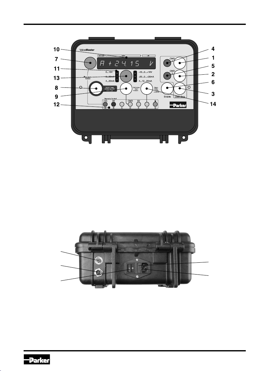
Setting an internal command output
Before a valve is connected to the ValveMaster,
the internal command value should be disabled
to minimize risks. This operating condition is indi-
cated by a flashing command range LED (11) and
the lit CMD Mode button (9) and can be achieved
by turning on the ValveMaster (17) or by pushing
the corresponding button (9).
The deactivation of the internal command
value is equal to the activation of the exter-
nal command reference mode!
If the internal command value is disabled, you can
use the select button (13) to select all available
command ranges sequentially.
The correct command range for the valve
can be found in the operation manual de-
pending on the valve’s product code!
By selecting measuring channel D and pressing
the command button (1)(2) you can preset two
command values via the potentiometers (4)(5).
If you have found the correct command range to
the valve and selected it, you can activate the in-
ternal set point by pressing the CMD Mode but-
ton (9). The background lighting of the CMD Mode
button (9) extinguishes and the command range
LED (11) is lit permanently.
By default, the test unit now returns the value for
the zero position of the valve. In the command
range 4...12...20 mA it is 12 mA, in the command
range -10...0...+10 V it is 0 V and in the command
range 4...20 mA it is 4 mA.
By pressing a corresponding command button (1)
(2), the previously set command value is availa-
ble on Pin D&E of the valve plug. It is still possible
to change both command values via the potenti-
ometers (4)(5). Pressing the CMD Zero button (3)
brings the valve back to zero position.
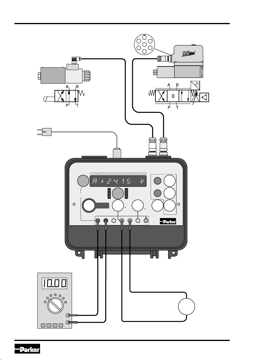
External command source
The ValveMaster is also able to use command val-
ues from an external source. These external sig-
nals are looped through to the valve and must be
in a range of ±10 V (for voltage) or ±20 mA (for
current).
Pay attention to the current flow direction
by current signals referring to the Pin D&E
(12)!
Before you connect an external source, ensure
that the ValveMaster is in external mode. The ex-
ternal mode is indicated by a lit CMD Mode but-
ton (9) and a flashing command range LED (11).
Now you can connect the external source to sock-
ets D&E (12).
The supplied signal value can’t be shown on the
display (10) because the measurement channel D
is only for the internal command values.
Operation of a DC(On/Off)-valve (max. 40 W)
The DC-valve will be connected via the enclosed
DC-cable to the ValveMaster connector (16). You
can operate the DC-valve by pushing the DC-
valve button (8). The operating status is indicated
by the DC-valve button lighting (8).
DC-valve on: LED on
DC-valve off: LED off
With a power drain greater than 40 W at the Valve
connector (16), the test unit triggers an error and
enters the fault condition mode.

8
EX-M05 40983307 UK.indd RH 15.07.19
Test Unit
Series EX-M05
Operation Manual
Parker Hannifin Corporation
Measurement selection (Pin A, C, D, F)
The pins A, C, D and F of the valve plug can be
selected sequentially as measuring point via the
selection button (7). The measured value is dis-
played on the measurement display (10).
Diagnostic signal selection (Pin F)
Diagnostic signals that are send by valves on the
pin F of the valve connector can be displayed on
the measurement display (10). A distinction is
made between voltage signals (up to ± 24 V) and
current signals (up to ± 20 mA). The signal selec-
tion is made with the Diagnostic Mode button (14)
and will be displayed by the button lighting (14).
Voltage measurement: LED off (default)
Current measurement: LED on
Enable signal (Pin C)
Some valves need an “enable” signal for opera-
tion which is switched on or off by pushing the En-
able button (6). The button lighting indicates the
status.
Enable active: LED on
Enable off: LED off
If there is a faulty connection to the C pin the
enable signal will be automatically switched off,
blocked or the current flow will be limited to 5mA
depending on the type of signal. This will prevent
damage to the electronics of valve and/or testing
unit.
Acknowledgement on fault condition
If the unit detects an operating error the Valve-
Master enters an error state. This is indicated by
sequential flashing of the measurement display
digits (10) and the CMD Zero lighting (3).
Before you acknowledge and quit the error state,
the fault must be localized and remedied.
After the fault has been remedied, you can press
the CMD Zero button (3) to quit the error state and
release the ValveMaster to further operation.
Measurement with an external measuring de-
vice
By connecting an external measuring device to
the test jacks (12), the measure-ment accuracy
can be increased.
Table of contents
Other Parker Test Equipment manuals