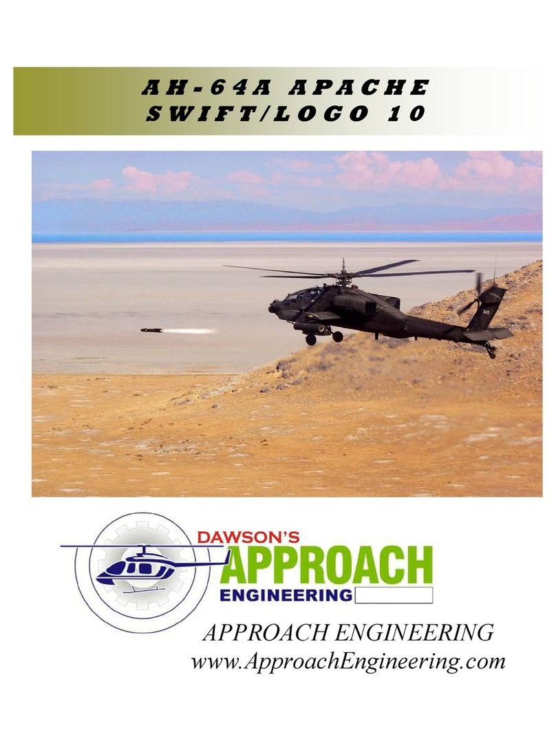
Approach Engineering AH-64A Apache-50 User manual

A H - 6 4 A A P A C H E – 5 0
Dawson’s APPROACH ENGINEERING
www.ApproachEngineering.com
Ridgecrest, CA. 9 555

APACHE 50 PAGE # 2
Dawson’s APPROACH EGIEERIG
AH-64A 50 MECHAICS
1.0 Purpose
To establish a process that ensures control and standardization in the anufacturing of AH-64A Apache for use with 46 size
echanics. Part Nu ber AP-100.
2.0 Tools Require
Note: (A) denotes tools required for asse bly and
(T) denotes tools required for testing.
Basic Hand Tools (A, T)
Epoxy 30 Minute (A)
Cyanoacratulate (CA) (A)
3.0 Reference Documents
Exploded view drawing appendix AH-64A Apache part nu ber AP-100. (A, T)
4.0 Limitation of liability
Accessing and using this Product and any infor ation contained therein is at your own expense and risk. Under no circu stances
will Dawson’s Approach Engineering, or any of its affiliated co panies, nor any directors, e ployees and agents, nor any third party
which has supplied infor ation for this Product accept any liability for any costs incurred and/or da ages suffered (including direct,
indirect or consequential da age or da ages, as well as loss of inco e or profits.) by you as a result of your use of the Product or
any infor ation contained therein.
5.0 Intro uction
1. WARIG This aircraft is not a toy. It is capable of serious bodily har and property da age. Every precaution
ust be taken to properly build this kit and install all radio co ponents. It is your responsibility alone to ensure all
safety steps are taken outlined in the Acade y of Model Aeronautics safety codes. If this is your first ti e building a
aircraft kit it is highly reco ended that you find experienced help for the first flights. Consult your local hobby shop
or write to the AMA for further guidance.
Acade y of Model Aeronautics
5151E. Me orial Drive
Muncie, IN 47302 (800) 435-9262
2. Please inspect all parts before building. If any parts are broken or issing please feel free to call or write for replace-
ent. The CD includes pictures of the full size aircraft to aid in finish sanding and detailing. If you have any ques-
tions, co ents, or i prove ents please call or write to:
Dawson’s Approach Engineering
220 W. Mariposa Ave.
Ridgecrest, CA. 93555
3. We as the kit anufacturer can provide you with assistance and a top quality kit and instruction anual. When built
light, straight, and true you will have a odel that flies as well as it looks on the ground. However the finished product
depends on the quality built into it. We can not guarantee the flight perfor ance. Take your ti e and read all instruc-
tions carefully before and during construction.
4. During the asse bly procedure the use of the ter CA refers to thin CA glue and CA+ refers to ediu viscosity glue.

APACHE 50 PAGE # 3
Dawson’s APPROACH EGIEERIG
AH-64A 50 MECHAICS
6.1 Punch out the two Vertical Fra es, VF-1, fro 1/8” ply-
wood. Punch out the two Vertical Fra e cross e bers, VF-2
and VF-3. The vertical fra e cross e ber VF-2 is asse bled
into the lower slot. VF-3 is asse bled flush with the upper sur-
face of the vertical fra e sides. Glue the cross e bers into
the slots of the vertical fra e sides.
6.2 Punch out the vertical fin base, F-6, and the pushrod con-
trol horn ount, VF-4, fro the 1/8” plywood sheet. Note,
depending on the tail rotor gearbox used deter ine if the ount
will be best situated on the right or left side. Picture shows
ount on the right side.
6.3 Punch out the tail bulkhead, F-7, fro the 1/8” plywood
sheet. Using CA+ glue it onto the base. Make sure that the
control ount is faced up with the s aller end of the for er.
Trial fit the vertical fin asse bly into place. Using the alu i-
nu tail rotor tube Dre el the edges of the ellipse that it will
protrude through on the base to fit at the angle.
6.4 Using a s all a ount of epoxy, glue the vertical fin as-
se bly into the notches of the base asse bly. Take ti e to
ensure that it is all asse bled square.
6.5 Using 220 grit sandpaper roughen up the tail rotor tube in
the areas that will contact the fra e supports.
6.6 Punch out the two 1/8” plywood leading edge tail rotor
fra e for ers VF-4. Using epoxy glue the into the slots to
hold the tail rotor tube fir ly in place. Make sure that the open-
ing to the tube is facing foreword. The lower leading edge
should co e flush with the botto of the vertical fin base.
6.0 VERTICAL FI FRAME
ASSEMBLY
VF-1
VF-3
VF-2
Roughen Area
Contour leading and
Trailing edge for tail rotor tube.
Open Slot in Tube
Lower Edge of Tube
Flush With Lower Surface
Approxi ately 3/8”

APACHE 50 PAGE # 4
Dawson’s APPROACH EGIEERIG
AH-64A 50 MECHAICS
6.7 Asse ble the control horn as shown below.
6.8 Punch out the two VF-4 bell crank supports. Glue one VF-
4 to each side of the Depending on which side the bell crank is
on double up the support by adding another VF-5 on inside
surface, and two VF-5 1/8” light ply doublers on the outside
surface.
6.9 Put the bell crank with the boss to the side of the ount.
Slide the 5/32” brass sleeve into the ount and position the
3/16” brass sleeve as a spacer. Glue the outside of the 5/32”
tube on both ends to secure in place.
6.10 Attach the pushrod to the tail rotor bell crank aking
sure that the ar is perpendicular to the pushrod.
6.0 VERTICAL FI FRAME
ASSEMBLY
otes:
Clevis
5/32” Brass Sleeve
3/16 Brass Sleeve
Bell crank
VF-5
VF-5
VF-5
5/32” Brass Sleeve
3/16 Brass Sleeve
VF-4

APACHE 50 PAGE # 5
Dawson’s APPROACH EGIEERIG
AH-64A 50 MECHAICS
7.1 Asse ble the side fra es by laying out the A and B sides.
The fuselage side is ade up of three separate pieces. The pro-
vided tabs allow for proper align ent and asse bly of the fuse-
lage sides. Put the tabs together and apply a s all a ount of
CA to the joints.
7.2 Place the co pleted asse blies of the fuselage side fra es
and lay the out to build a right and left half. Place the opening
of the fuselage side so that it will be built up on the right side.
Using 30 inute epoxy glue on the fuselage doublers FD-1 and
FD-1B by aligning the cut outs on the doublers and the fuselage
sides. Set aside and allow to set.
7.3 Cut out the two each upper tail boo filler, UTF, and
lower tail boo filler, LTF, fro 1/4” balsa. Align the edges
and glue into place aking sure to allow the 1/8” slot clearance
between the two for the tail boo fra e.
7.4 Using 3/4” triangle stock, fit along the edge of the fuselage
sides fro the back of the fuselage doublers to the back edge of
the tail boo fillers. Repeat the procedure along the top edge
fro the bend in the side sheeting to the back edge of the upper
tail boo filler. Note, the triangle stock has to be cut at the
bends of the fuselage sides and ate together flush.
7.5 Punch out F-1, F-2, and F-5. Asse ble the fuselage by
installing for ers with the co pleted fuselage sides. Make sure
to have the for ers square to ensure a straight fuselage. Glue
with CA.
7.6 Cut out the 1/4” light ply fuselage botto . Epoxy into
place aking sure that the end labeled “Front” is facing to the
front of the fuselage.
7.0 FUSELAGE ASSEMBLY
PROCEDURE
S-1A
S-2A
S-3A
S-1B
S-2B
S-3B
FD-1
FD-1B
FD-1
FD-1B
Opening in
Fuselage Side
F-1
F-2
F-5

APACHE 50 PAGE # 6
Dawson’s APPROACH EGIEERIG
AH-64A 50 MECHAICS
7.7 Trial fit the vertical fin asse bly into the left side of the
fuselage sides. Make sure to have the notches in the fuselage
side properly fit the vertical fin asse bly. Once satisfied apply
epoxy the left side only and fully asse ble the tail and hold
together with rubber bands or tape and allow to set.
7.8 Install the 36” tail rotor control tube by sliding it through
the holes in F-2 and F-5. The end should co e to about 1.5”
fro the tail rotor control horn. When in place glue the outer
tube to F-2 and F-5 using CA+.
7.9 Asse ble the pushrod tube and slide inside the pushrod
tube. Securely ount the pushrod end to the control horn.
7.10 Cut out the 1/4” balsa pushrod block, PB-1 and PB-2.
Position the block between the fuselage side sheeting and the
pushrod outer tube to allow the pushrod to be as straight as pos-
sible. Once in position glue in place with CA+.
7.11 Install the second pushrod tube down the right side of the
fuselage in the sa e anner as before. Bend the inner pushrod
wire to the shape as shown in the appendix. Feed into the front
lower hole and through the pushrod tube hole on F-7.
7.12 Using epoxy glue the right fuselage side to the vertical
fin asse bly and allow to set. Hold the sides together with tape
until the glue sets.
7.0 FUSELAGE ASSEMBLY
PROCEDURE
Control Tube
PB-1
Hold with Tape
Epoxy only Left Side for now PB-2

APACHE 50 PAGE # 7
Dawson’s APPROACH EGIEERIG
AH-64A 50 MECHAICS
7.13 Using two pieces of 1/4” balsa square stock by 1.5” long
glue between the horizontal fin pushrod tube along the right
side. Keep the pushrod tube as straight as possible.
7.14 Cut out two 3/4” balsa triangle stock by 5.75” long fro
the triangle stock. Turn the fuselage over and tri the triangle
stock as necessary to fit in the aft section of the fuselage. Glue
in
7.15 Cross sheet the lower section of the fuselage using 3/32”
balsa sheet. Set the fuselage up square in order to not build a
twist into the fuselage. Starting fro the aft section of the fire-
wall to the end of the tail boo .
7.16 Slide the driveshaft tube starting fro the top of the tail
boo and slide it through the support. The tube will co e out
of the slot in the tail boo and through the center hole of the
fra e base. Continue to feed it through until the end of the tube
is just above the top of the tail boo .
7.17 Cut two 3/8” by 3” balsa triangle fro the triangle stock.
Glue the triangle stock to the base of the lower sheeting and to
the drive shaft tube. Make sure that the tube is straight down
the center.
7.18 Pull out the two 3/4” by 2.25” balsa triangle stock. Fit
and cut as necessary between the upper triangle stock and the
vertical fra e supports. Glue in place with CA+. The upper tail
boo sheeting will be co pleted later.
7.0 FUSELAGE ASSEMBLY
PROCEDURE
Tail Rotor Tube
Outer Housing
Triangle Stock

APACHE 50 PAGE # 8
Dawson’s APPROACH EGIEERIG
AH-64A 50 MECHAICS
7.19 Apply ¼” x 10” triangle stock on the firewall and fuse-
lage doublers interface. The triangle stock should go full length
of the firewall. Glue in place with epoxy.
7.20 Cut and glue ½” x 6.7” triangle stock between the fuse-
lage doublers and the lower sheeting between the firewall and
F-3. Co plete for both the right and left side.
7.21 Pull out the two 1/2” x 1.5” square lower landing gear
blocks. Slide the 5/16” dia eter brass tube through both land-
ing gear blocks.
7.22 Slide the ain landing gear blocks into place so that the
outside fuselage surface and the landing gear block is flush.
When satisfied with the fit glue in place with Epoxy.
7.23 Epoxy the two 1” by 1/2” balsa triangle stock to the up-
per edge of the landing gear blocks.
7.24 Punch out the 3/32” balsa trans ission backing sheets,
TB-1 and TB-2, and the canopy backing sheets, CB-1 and CB-
2. Align as necessary and glue into place with CA+.
7.0 FUSELAGE ASSEMBLY
PROCEDURE
Triangle Stock
TB-2 TB-1 CB-2 CB-1

APACHE 50 PAGE # 9
Dawson’s APPROACH EGIEERIG
AH-64A 50 MECHAICS
7.25 Install the upper 1/2” by 3/4” long landing gear blocks in
the sa e anner as the lower blocks. Use 1/4” triangle stock to
strengthen the landing gear blocks.
7.26 Install the two 1/4” x 3/8” basswood servo rails. The
foreword rail should be pushed up against F-1. Adjust the width
to acco odate your servos.
7.27 Te porarily install the tail rotor servo, right side, and
optional horizontal stabilizer servo, left side. Drill appropriate
ounting screws.
7.28 ote Depending on the echanics you are going to use
will deter ine if you need this support. Raptor echanics re-
quire the adapter and this step is obsolete. Punch out the ¼”
balsa tail rotor driveshaft support DS-1. Slide it over the drive-
shaft tube into place up against the upper triangle stock and
flush with the top. Glue with CA+.
otes:
7.0 FUSELAGE ASSEMBLY
PROCEDURE
Flush
Triangle Stock

APACHE 50 PAGE # 10
Dawson’s APPROACH EGIEERIG
AH-64A 50 MECHAICS
8.1 Punch out the Nose Sides, NS-1, Nose Top, N-T, and Nose
Botto , N-B fro the ¼ inch balsa sheet. Make sure that the
nose side pieces have the labeling both up to ake sure that the
nose top and botto are glued at the proper angle. Glue to-
gether to for a open box as shown using CA+.
8.2 Punch out the two nose filler blocks, N-F, fro the ¼”
balsa sheet. Note: the filler blocks ust be glued foreword to a
point so that when the nose is sanded they will be sanded flush
as well. As a approxi ate guide it will be about 3/16” fro the
trailing edge. Glue on each inside lower corner with CA+.
8.3 Cut out two 3/4” triangle stock approxi ately 2.5” in
length. Glue in place so that they will overhang both the lower
inside corners of the nose so that when the front and back face
are sanded flat they will be flush as well.
8.4 Sand the front and the back of the nose section flat. For
best results lay a piece of sandpaper on a flat surface and sand
the entire surface at the sa e ti e. Sand until all the darker
laser cut edges of the side pieces are sanded away.
8.5 Cut out two 3/4” balsa triangle stock approxi ately 3”
inches in length. Glue in the upper inside edge of the nose as-
se bly so that the ends overhang the front and rear face to al-
low for sanding. Sand the triangle stock flush with the front and
back surfaces.
8.6 Punch out the TADS/PNVS front plate, NS-F fro the ¼”
inch balsa sheet. Outline the profile of the front plate onto the
nose asse bly. Do not glue on at this ti e.
8.0 TADS AD PVS
COSTRUCTIO
N-T
N-S
N-B
N-F
N-F

APACHE 50 PAGE # 11
Dawson’s APPROACH EGIEERIG
AH-64A 50 MECHAICS
8.7 Using the supplied pictures sand the nose asse bly to the
finished shape. Do not sand the rear edges where it will fit to
the fuselage asse bly.
8.8 Glue the TADS front plate back onto the nose asse bly.
8.9 Punch out the TADS/PNVS support plate, NS-S, fro the
¼ inch balsa sheet. Using the slot provided glue it to the front
of the TADS/NVS front plate so that it is perpendicular to this
plate.
8.10 Punch out the two triangular TADS/PNVS side supports,
TD-S, fro 3/32” balsa. Glue in the notch ade by the TADS/
PNVS support plate to the back plate.
8.0 OSE COSTRUCTIO
OTES: Set aside the fuselage nose until later in the asse -
bly.

APACHE 50 PAGE # 12
Dawson’s APPROACH EGIEERIG
AH-64A 50 MECHAICS
9.1 Punch out two each of the foreword avionics bay for ers
F-3 and F-4 fro the 1/16” balsa sheet. Glue the into their
respective slots on the outside of both of the fuselage sides
while aking sure that they stay perpendicular to the surface.
9.2 Punch out the foreword avionics bay side, FAB-1, fro the
1/16” balsa sheet. Note: This bay side goes on the opposite
side as the open fuselage side. Align and glue to the for ers F-
1, F-2, F-3, and F-4 using the notches provided and aligning the
edges.
9.3 Punch out the ¼” balsa foreword avionics bay base, FAB-
B, and the 1/16” bay side 2, FAB-2. Glue the bay base into the
notches on the lower edge of the fuselage side. Align and glue
to the for ers F-1, F-2, F-3, and F-4 using the notches provided
and aligning the edges.
9.4 Cross sheet the re ainder of the lower fuselage with 3/32”
balsa so that it extends out to the sides of the bay sides.
9.5 Glue the co pleted tads front nose section to the nose of
the fuselage asse bly so that the side and botto edges are
aligned.
9.6 Using 3/32” balsa sheet cross sheet the upper surface of
the foreword avionics bays. Co plete for the left and right
sides.
9.0 FOREWARD AVIOICS
BAY COSTRUCTIO

APACHE 50 PAGE # 13
Dawson’s APPROACH EGIEERIG
AH-64A 50 MECHAICS
9.7 Punch out the two ¼” balsa foreword avionics bay doors,
FAB-D. Make sure to build a right and a left side. Sand both
doors fro a rounded do e shape in the center to a tapered
feathered edge on the edges. Note: depending on your covering
technique you ay want to cover the non functional door before
per anently
gluing it to the
FAB. When
satisfied glue to
the side of the
foreword avion-
ics bay side
sheeting.
9.8 Hinge the working bay door with pinned hinges. The
hinges should have the slots cut along the 1/4” balsa edge going
back at an angle. Punch out the FAB door base, FAB-DR. Glue
to the botto edge of the FAB door that will cover the opening
to allow the electronics access.
9.9 Fit the door in place and ake atching hinge slot cuts in
the 1/4” balsa avionics bay floor. The ends of the hinges ay
be tri ed for appearance. Do not per anently glue the
hinges until after finishing.
9.10 Using the sticker paper te plate for the upper landing
gear hole place the edge 1/4” behind for er F-2. Using a razor
cut a hole in the upper foreword avionics bay sheeting.
9.11 Cross sheet the re ainder of the lower sheeting of the
avionics bays with 3/32” balsa. Cut out the sheeting 1” long
starting fro the front edge of the lower landing gear block.
9.12 Sand and fit the two FAB nose blocks to the front of the
avionics bays. Sand to desired final shape.
9.0 FOREWARD AVIOICS
BAY COSTRUCTIO
1/4” X 3/8” Balsa Stock
Sand to nose angle and ark pro-
file
Rough sketch shape and cut out.
Sand to final shape.

APACHE 50 PAGE # 14
Dawson’s APPROACH EGIEERIG
AH-64A 50 MECHAICS
10.1 Punch out the two 3/32” balsa canopy sides and the two
1/8” plywood canopy guide teeth CGT. Making sure to build a
right and a left side position the guide teeth so that the botto ,
front, and rear edges all are flush. Glue 1/4” balsa triangle stock
along the upper edge displayed by the laser pattern. The trian-
gle stock will extend past the upper edge.
10.2 Punch out the three canopy for ers CF-1, CF-2, and CF-
3. Using CA+ only glue up about the first inch of the for ers
and build a box structure with the canopy sides. Take ti e and
ake sure to build a straight canopy.
10.3 Apply CA+ to the re aining edge of the for ers and
press the sides of the canopy up to atch. Sand the 1/4” trian-
gle that is extending past the canopy sides to eet the canopy
sides.
10.4 For best results te porarily install the canopy into the
fuselage for fit and align ent. Starting fro the back of the
canopy, cross sheet the upper surface of the canopy with 3/32”
balsa sheet up to the sharp bend over the front cockpit. Allow a
s all a ount of sheeting to extend past.
10.5 Using a sanding block sand the sheeting to atch face of
the front glass. This will produce a feather edge of the sheeting.
10.6 Cross sheet the front canopy allowing a s all a ount of
sheeting to extend past the sanded edge.
10.0 CAOPY COSTRUCTIO
CF-1
CF-2 CF-3
1/4” Triangle
CGT

APACHE 50 PAGE # 15
Dawson’s APPROACH EGIEERIG
AH-64A 50 MECHAICS
10.7 Sand the front canopy sheeting to atch the upper can-
opy cross sheeting. This will give a clean edge with increased
strength. Take the canopy off the fuselage and apply thick CA
to all the corners of canopy cross sheeting fro inside the can-
opy. This will increase the strength.
10.8 Punch out the three canopy/trans ission nose blocks,
CNB, out of the ¼” balsa sheet. Glue the three blocks together
aking sure to build the up straight.
10.9Sand the canopy/trans ission nose block to the desired
finished shape as shown in the picture. Glue on top of the can-
opy so that the back edge is flush with the back of the canopy.
10.10 Using the sticker te plates 1, 2, and 3, align and place
on the upper surface of the canopy.
10.0 CAOPY COSTRUCTIO
10.11 Using a straight edge cut along the lines of the te -
plates to cut out the window shapes. Cut out and check fit of
the canopy glass. Install after finishing the canopy.
10.12 Te porarily install the canopy on the fuselage and sand
the nose section to atch the canopy profile.

APACHE 50 PAGE # 16
Dawson’s APPROACH EGIEERIG
AH-64A 50 MECHAICS
11.1 Punch out the two trans ission sides, T-1, fro the 3/32
balsa sheets. Punch out the two Trans ission guide teeth, TGT,
fro the 1/8” plywood. Lay the trans ission side fra es to
build a right and a left. Using CA+ glue the two trans ission
guide teeth to the trans ission side fra es by aligning the edges
together at A and B as shown on the picture.
11.2 Punch out T-1 and T-2 fro the 1/8” plywood. Using
CA+ glue the trans ission by aligning the T-2 bulkhead with
the notches in the guide teeth. Using CA glue the for ers to the
trans ission side.
11.3 Punch out the trans ission top sheet, T-T, fro the 3/32”
balsa sheet. The front edge of the top sheeting is notched and
slides into the T-1 bulkhead. Align the sides of the trans ission
sides with the edge of the top sheet. Glue with CA+.
11.4 Cut out two lengths of 1” triangle stock with a length of
3”. In the front top corner of the trans ission side and the T-1
glue the triangle stock in place with CA+ to allow sanding to the
final shape.
11.5 Cut and sand the triangle stock to atch the inside profile
of the T-1 for er.
11.6 Sand the corners of the trans ission to atch the profile
that is laser arked into the face of T-1. The top sanded profile
should atch the upper trans ission sheeting. This is the out-
line of the canopy
11.0 TRASMISSIO BAY
ASSEMBLY
A
A
B
B
T-1
T-2

APACHE 50 PAGE # 17
Dawson’s APPROACH EGIEERIG
AH-64A 50 MECHAICS
11.7 Punch out the two doghouse side pieces, DH-S, and dog-
house top, DH-T, fro the 3/32 balsa sheets. Glue the dog-
house side pieces to the botto of the doghouse top so the front
edge of the side is aligned with the corner of the top. Using
CA+ glue the doghouse asse bly to the top of the trans ission
so that the front edge of the top sheeting is flush with the front
face of T-1.
11.8 Sand the back of the trans ission doghouse top sheeting
and upper trans ission sheeting to atch the angle of the trans-
ission. When finished sanded each sheeting should be sanded
to a feather edge which will allow cross sheeting.
11.9 Te porarily place the trans ission on the fuselage. Glue
pieces of scrap balsa on the inside edge of the trans ission
sides to hold the surfaces of the trans ission and fuselage side
flush. Using so e asking tape pull the sides of the fuselage
together to ake sure that the sides are parallel for sheeting.
11.10 When satisfied cross sheet the back of the trans ission
fro the back edge to the doghouse top with 3/32” balsa sheet.
11.11 Cut out two ½ inch by 8” triangle stock and glue along
the inside upper edge of the trans ission side starting behind T-
2 to the trailing edge. This will aid in sanding a rounded pro-
file.
11.0 TRASMISSIO BAY
ASSEMBLY
otes:
Scrap balsa for edge
align ent.
DH-T
DH-S
Tape

APACHE 50 PAGE # 18
Dawson’s APPROACH EGIEERIG
AH-64A 50 MECHAICS
12.1 Punch out the two 3/32 balsa Engine E-1, E-2, and the
two engine nacelle side pieces EN-S. Note: E-1 is perpendicu-
lar to the trans ission side where E-2 will be at a angle deter-
ined by the slots in the fuselage and nacelle sides. Glue E-1
first perpendicular to the side. Without gluing install E-2 and
the nacelle side. When satisfied with the fit glue with CA+.
12.2 Turning the trans ission asse bly over to work on the
botto of the engine nacelles. Punch out one each of the na-
celle sheeting, EN-1, for the botto of each nacelle. Align the
edges and glue in place with CA+.
12.3 Punch out the lower nacelle build up piece, EN-2, and
glue it on the inside outboard lower corner of the engine nacelle.
12.4 Glue the side engine nacelle filler, EN-F, on top of EN-2.
Cut out a piece of 3/4” by 2.5” triangle stock. Round off one
end and glue in the front corner ade by the two engine nacelle
filler pieces.
12.5 Cut out two lengths of ½ by 5 1/2” triangle stock to fit
along the upper nacelle outboard surface. The ends should
atch with the for ers.
12.6 Punch out the ¼” balsa nacelle fillers EN-3. Sand the
end to atch the angle ade by the for er E-2. Glue in the
inside rear corner of the nacelle so that the top is flush with the
for er EN-4.
12.0 EGIE ACELLE
ASSEMBLY
EN-1
E-2
E-1
Flush

APACHE 50 PAGE # 19
Dawson’s APPROACH EGIEERIG
AH-64A 50 MECHAICS
12.7 Punch out two for each of the nacelle exhaust side EN-4.
Glue one on the top and botto inside surface of the nacelle
side so that their surfaces are flush with the top edge of the na-
celle side.
12.8 Sheet the top of the engine nacelle by using the 3/32” cut
out EN-1. Glue in place with CA+.
12.9 Punch out two engine nose blocks, ENB, for each na-
celle. Make two sets of two blocks by gluing two each together.
12.10 Making sure to build a right and a left, draw a line in
pencil about 3/8” around the center hole to aid in sanding. Sand
the edge that will go up against the fuselage side to the rounded
scale shape as shown. Sand the center circle to a radius reach-
ing out to the line drawn. This prevents co plication in sanding
later. The other edges are sanded after it is glued to the front of
the nacelles.
12.11 Position the engine nose block asse blies so that the
one sanded edge is up against the trans ission side and the
other three edges align with surfaces of the engine nacelle.
Glue the co pleted asse blies to the front of the engine na-
celles using CA+. Make sure that the glue is placed on the back
flat face of the nose block for sanding purposes.
12.12 Sand the outside upper and lower corners of the engine
nacelle by first atching the shape of the nose block. The ra-
dius tapers off toward the end of the nacelle. Round the nose
block into a rounded shape blending it into the nacelle. Sand
the corner of the exhaust cover EN-4 to a rounded shape .
12.0 EGIE ACELLE
ASSEMBLY

APACHE 50 PAGE # 20
Dawson’s APPROACH EGIEERIG
AH-64A 50 MECHAICS
13.1 Punch out six 1/4” balsa nose gearbox bodies, NGB-1.
Building a right and left sides glue three each together by align-
ing up all edges.
13.2 Lay out the asse blies to ake a right and left gearbox.
Punch out one each of the nose gearbox front, NGB-2, and glue
on the front of each gearbox atching the outside profile.
13.3 Turn the asse blies over to work on the back side. Us-
ing two each of ¼” balsa gearbox bases, NGB-3, glue on the
back center of each gearbox.
13.4 Using the included instruction anual photos and the
aircraft photos sand the gearbox to it’s final sanded shape.
13.5 Punch out the two 1/8” plywood engine intake swirl
vanes, EN-I, and sand to a desired finished shape. This is cos-
etic purposes only. The blades ay be shaped like propellers
to si ulate the intake swirl vanes. Depending on the desired
finishing technique it is reco ended to glue in place later.
OTES:
13.0 OSE GEARBOX
ASSEMBLY
NGB-4
NGB-4
NGB-3
Other Approach Engineering Toy manuals
Popular Toy manuals by other brands

Lionel
Lionel 1464W UNION PACIFIC Instructions for operating

E-FLITE
E-FLITE P-51D Mustang instruction manual

Sol-Expert
Sol-Expert 1818584 Quick user guide

THE WORLD MODELS
THE WORLD MODELS Clipped Wing Cub EP instruction manual

V-tech
V-tech KidiCreative Kidi ART Studio user manual

Step 2
Step 2 Deluxe Canyon Road Train & Track Table 7547 Assembly manual

WATT AGE
WATT AGE PT-19 CORNELL EP ARF Instructions for final assembly

V-tech
V-tech MobiGo Game Storage instructions

V-tech
V-tech Artificial Intelligence DeskPro user manual

V-tech
V-tech Tool Box Friends Parents' guide

V-tech
V-tech Birdie Travel Mobile Parents' guide

V-tech
V-tech Sparkle & Shine Unicorn instruction manual