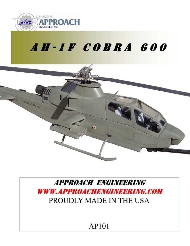
Approach Engineering AH-1F Cobra Electric Guide

A H - 1 F C O B R A
E L E C T R I C
APPROACH EGIEERIG
www.ApproachEngineering.com

AH-1F COBRA—ELECTRIC PAGE # 2
APPROACH EGIEERIG
AH-1F ELECTRIC MECHAICS
1.0 Purpose
To establish a process that e sures co trol a d sta dardizatio i the ma ufacturi g of AH-1F Cobra for use with electric
mecha ics. AP102.
2.0 Tools Required
Note: (A) de otes tools required for assembly a d
(T) de otes tools required for testi g.
Basic Ha d Tools (A, T)
Sa di g block a d paper (A)
Dremel Tool (A)
Epoxy 30 Mi ute (A)
Cya oacratulate (CA) (A)
.0 Reference Documents
Exploded View Pla s for AH-1F Cobra AP102. (A, T)
4.0 Attachments
5.0 Introduction
1. WARIG This aircraft is ot a toy. It is capable of serious bodily harm a d property damage. Every precautio
must be take to properly build this kit a d i stall all radio compo e ts. It is your respo sibility alo e to e sure all
safety steps are take outli ed i the Academy of Model Aero autics safety codes. If this is your first time buildi g a
aircraft kit it is highly recomme ded that you fi d experie ced help for the first flights. Co sult your local hobby shop
or write to the AMA for further guida ce.
Academy of Model Aero autics
5151E. Memorial Drive
Mu cie, IN 47302 (800) 435-9262
2. Please i spect all parts before buildi g. If a y parts are broke or missi g please feel free to call or write for replace-
me t. All i structio ma ual photos are i cluded with the CD alo g with other scale docume tatio pictures to ease i
fi ishi g. If a step or photo appears u clear to you i spect the CD for additio al photos with differe t views to aid i
assembly If you have a y questio s, comme ts, or improveme ts please call or write to:
Approach E gi eeri g
Ridgecrest, Ca. 93555
www.approache gi eeri g.com
3. We as the kit ma ufacturer ca provide you with assista ce a d a top quality kit a d i structio ma ual. Whe built
light, straight, a d true you will have a model that flies as well as it looks o the grou d. However the fi ished product
depe ds o the quality built i to it. We ca ot guara tee the flight performa ce. Take your time a d read all i struc-
tio s carefully before a d duri g co structio .
4. Duri g the assembly procedure the use of the term CA refers to thi CA glue a d CA+ refers to medium viscosity glue.

AH-1F COBRA—ELECTRIC PAGE # 3
APPROACH EGIEERIG
AH-1F ELECTRIC MECHAICS
6.1 Pu ch out the four 3/32” fuselage side pieces for each side.
Assemble the side frames, (S-1, S-2, S-3, S-4) over a piece of
wax paper. The provided tabs allow for proper alig me t a d
assembly of the fuselage sides. Build a right a d a left taki g
ote of the tria gle stock refere ce li es a d have them faci g
up. These will aid i the i stillatio of the tria gle stock. Usi g
the otches provided assemble a d glue with CA the two fuse-
lage sides.
6.2 Place the completed assemblies of the fuselage side frames
a d lay them out to build a right a d left half. Have the tria gle
refere ce li es up so that they will be o the i side of the as-
sembly. Alig the fuselage doublers, FD-2, a d FD-3 by match-
i g the fro t otch edge (A), the ca opy top edge (B), a d the
bottom of the wi g otch (C) with the fuselage side. The
otches i the fuselage for F-3 a d F-4 will li e up with the
otches i the fuselage doublers. Usi g 30 mi ute epoxy glue
o the fuselage doublers. Set aside a d allow to dry.
6. Usi g laser pri ted tria gle stock refere ce li es, Glue ¾”
tria gle stock (TRI-2) alo g the bottom edge of both i er sur-
faces of the fuselage side betwee F-4 a d the tail boom e d
filler. Glue ¾” tria gle stock (TRI-3) alo g the upper edge of
the fuselage sides. Glue the 3/32” horizo tal fi doublers
(HFD) to the i side surface of the fuselage sides.
6.4 Glue F-3, with the text a d curved edge faci g up, a d F-4
i to the otches of the fuselage doublers to make the fuselage
box. Usi g epoxy glue i the two mecha ics mou ts i to the
otches of the fuselage doublers. Epoxy the formers a d
mou ts i to the other side of the fuselage.
6.5 Temporarily positio your mecha ics a d mark mou ti g
poi ts o the mecha ics mou ts.
6.6 Drill holes i the mecha ics mou ts o the marked posi-
tio s with a 9/64” drill bit. Press i the four 4-40 bli d uts o
the bottom side of the mecha ics mou ts. Logo mecha ics
mou t directly to the base which is assembled later. You will
wa t to fit the mecha ics a d properly place the mai shaft ce -
tered i the hole i the doghouse.
6.0 FUSELAGE ASSEMBLY
A
B C
FD-2 FD-3
Match a gle o
e d of tri stock.
HFD
Note: Logo mecha ics do ot
use the rails. Check fit prior to
assembly.

AH-1F COBRA—ELECTRIC PAGE # 4
APPROACH EGIEERIG
AH-1F ELECTRIC MECHAICS
6.7 Tur the fuselage over a d epoxy the 1/4” light ply fuse-
lage bottom to the i side of the fuselage sides. Pu ch out the
1/4” chi block, CB, a d glue to the fro t of the plywood fuse-
lage bottom.
6.9 Worki g at the ose of the fuselage sides cut 3/4” tria gle
stock (TRI-1) to match the bottom fro t edge to F-3 o each
fuselage side. The e ds of the tria gle stock should mate up
flush with F-3 a d should exte d past the fro t fuselage side
edge to be sa ded off later. Cut parallel cuts to approximately
1/8” of the back surface to aid i the fuselage ose i be di g
6.11 Apply water to the fuselage side ose a d the tria gle
stock to aid i be di g. Usi g maski g tape be d the sides to
glue F-1 i place.
6.8 Tur the fuselage assembly over a d glue the four 1/2” by
1.5” square hardwood la di g gear blocks usi g epoxy. Try ot
to fill the 5/16” holes with epoxy o the e d of the la di g gear
blocks.
6.10 Glue the ¾” tria gle stock to the bottom edge of the ose
to F-3.
6.12 Glue F-2 alo g the ca opy side matchi g up the upper
edge.
6.0 FUSELAGE ASSEMBLY
La di g Gear Blocks
Match upper edge
CB
PLY
BASE

AH-1F COBRA—ELECTRIC PAGE # 5
APPROACH EGIEERIG
AH-1F ELECTRIC MECHAICS
6.1 Pu ch out the two 1/8” light ply vertical fi supports a d
two tail rotor tube supports (TSR). The rou ded edge of the tail
rotor tube support faces foreword. Glue the two TSR supports
i the mid a d lower slots o o e side o ly.
6.15 Assemble each pulley idler assembly by first pushi g the
1/8” shaft through the beari gs. Place o e bushi g o each side
so that the e d of the shaft is flush with both sides. Complete for
both idlers.
6.17 Pu ch out the 1/8” ply tail rotor frame base (TFB).
Note: the base has a break out tab that will be removed later at
the fro t of the part. Do ot cut at this time. Slide the vertical
fi supports i to the base a d glue with CA+.
6.14 Assemble the two belt idlers pulleys as show . The
chamfered edge of the pulleys should face i ward to help guide
the belt.
6.16 Place the toothed idler assembly i the lower hole a d the
smooth idler i the upper hole. Take the supplied belt, ot the
o e with your mecha ics, a d place it betwee your idlers so
that the teeth are faci g toward the toothed idler. Glue the other
vertical fi support to the tube supports. You may place a small
amou t of glue o the outside of the bushi gs to help hold them
i place.
6.18 Glue o the 1/8” ply side pulley doublers (SPD) to the
outside of each pulley assembly by alig i g the edges.
6.0 FUSELAGE ASSEMBLY
Beari gs 2 each
Guide Washers 2 each
Note directio of teeth
Smooth Idler
Tooth Idler
Beari gs
TSR

AH-1F COBRA—ELECTRIC PAGE # 6
APPROACH EGIEERIG
AH-1F ELECTRIC MECHAICS
6.19 Cut out the 1/8” ply traili g edge former (TE-2) a d glue
it i to the otches provided o the top of the vertical fi assem-
bly.
6.21 Cut out three tail rotor tube leadi g edge supports (TSF)
from the 1/8” ply. Usi g 30 mi ute epoxy glue to the vertical
fi supports a d the tail rotor tube.
6.2 Attach the 4-40 threaded shaft a d li k to the bell cra k
for the vertical portio . Attach a other li k to the lower bell
cra k arm.
6.20 Pull out the larger diameter, lo ger, tail rotor tube with
the four vertical cuts i o e e d. Usi g 30 mi ute epoxy glue to
the vertical frame so that the bottom edge is flush with the bot-
tom surface of the bottom tail rotor tube support a d the vertical
cuts are at the top of the fi assembly..
6.22 Slide the 1/8” bell cra k shaft through the hole o the
sides of the vertical fi support a d hold i place with a drop of
CA o the outside e d of the shaft.
6.24 Glue the completed assembly i to the otches provided
i the fuselage side.
6.0 FUSELAGE ASSEMBLY
Bottom edges li e up.
TSF
Li k to tail rotor servo. The
pushrod will be co ected
later.
Vertical pushrod
a d li k.

AH-1F COBRA—ELECTRIC PAGE # 7
APPROACH EGIEERIG
AH-1F ELECTRIC MECHAICS
6.25 Make two sets of filler blocks by glui g o e filler block
side, FBS a d o e FBM to build a right a d left. Make a vertical
mark from the cor er of the FBM as a sa di g refere ce. The
face will be sa ded to that mark a d tapered to about 1/16” at
the tip.
6.27 Usi g your desired pushrod co ect it to the bell cra k at
this time. The outer housi g will be i stalled later. Usi g 1/4”
tria gle stock fill the gap betwee the FBM a d the tria gle
stock o both sides.
6.29 Sa d the horizo tal fi to the desired shape. Note: the
real aircraft has a flat top a d a rou ded lower surface. This
will pull the ose up i foreword flight a d is recomme ded to
sa d them to a symmetrical profile. Glue the ¼” x ¼” x 1-3/4”
balsa sticks i to the otches. These will go i to the fuselage
side a d doublers for i creased stre gth.
6.26 Worki g at the lower rear of the tail boom, trial fit the
filler blocks to e sure a good fit. Whe satisfied glue the filler
blocks i to positio .
6.28 Maki g two sets glue the upper a d lower horizo tal fi s
together, from the ¼” balsa, maki g sure to make a right a d a
left.
6. 0 Usi g 3/32” balsa cross sheet the bottom of the fuselage
starti g from behi d the fuselage floor to the e d of the tail
boom.
6.0 FUSELAGE ASSEMBLY
HF-B
HF-B
HF-T
Sa di g Mark
Co trol Rod
Co ector
1/4” Tri Stock

AH-1F COBRA—ELECTRIC PAGE # 8
APPROACH EGIEERIG
AH-1F ELECTRIC MECHAICS
6. 1 Usi g 3/32” balsa cross sheet the upper a d lower sur-
faces of the ose.
6. Remove the ce ter sectio of the vertical fi base to al-
low free moveme t of the belt drive. Also test fit the horizo tal
fi s for a proper fit. Do ot Glue the ¼” x ¼” x 1-3/4” balsa
sticks i to the otches. These will go i to the fuselage side a d
doublers for i creased stre gth.
6. 5 Pu ch out the 1/4” balsa tail rotor pushrod supports,
DDS-1 a d DDS-2, a d glue them o the bottom sheeti g sur-
face. Make sure that they are properly alig ed a d provide a
straight support for the pushrod. Whe satisfied glue the push-
rod outer tube to the supports with thick CA.
6. 2 Pu ch out the 1/8” ply ca opy backi g plate, CBT, a d
tra smissio backi g teeth, TBT. Matchi g up the profiles glue
them to the back of the fuselage doublers. This is to hold the
ca opy a d tra smissio guide teeth flush for a good fit.
6. 4 Slide the fro t pushrod tube support (DSS-3) up so that it
is supporti g the tube. The support should li e up with the tri-
a gle stock, sides, a d balsa cross sheeti g floor. Put the push-
rod tube through the hole that fits your desired servo layout.
Whe satisfied with the fit glue i place with CA+. Depe di g
o your radio arra geme t you may wa t to i stall a receiver
a te a wire tube ow for ease of i stillatio .
6. 6 Glue i the 3/8 tria gle stock alo g the balsa floor as
show . This will aid i sa di g a rou ded cor er. Apply tria -
gle stock to both sides.
6.0 FUSELAGE ASSEMBLY
DDS-1
DDS-2
1 1/2” lo g
6 1/4 Lo g
5 3/8” Lo g

AH-1F COBRA—ELECTRIC PAGE # 9
APPROACH EGIEERIG
AH-1F ELECTRIC MECHAICS
7.1 Sa d the face of the fuselage assembly flush with F-1.
Glue o the two 1/4” balsa TSU back plates (TSU-B) together.
Positio the otch toward the bottom of the fuselage a d glue
flush with the bottom a d sides of the fuselage ose.
7. Sa d rou ded cor ers o the three outside edges of the
TSU back plate.
7.5 Glue the TSU bottom pieces i to the otch i the TSU
back plate.
7.2 To aid i sa di g draw li es o the lower surface a d the
fuselage side ¾” from the sheeti g. Whe sa di g make a eve
tra sitio from li e to li e. Sa d the fuselage cor ers to their
fi ished rou ded shape.
7.4 Glue the two TSU bottom pieces, TSU-L, together. Mark
a li e 1/2” from the back edge as a sa di g guide. Sa d the
TSU bottom pieces from the li e at a co sta t a gle to about
3/32” up from the rou ded edge as show i the picture.
7.6 Glue the four ose blocks together starti g from NB-1 o
the bottom to NB-4 a d glue the assembly to the top of the TSU
back plate agai st F-1.
7.0 OSE AD TSU (TELESCOPIG
SIGHT UIT) ASSEMBLY

AH-1F COBRA—ELECTRIC PAGE # 10
APPROACH EGIEERIG
AH-1F ELECTRIC MECHAICS
7.7 Sa d the ose blocks flush with the top of the cross sheet-
i g o the fuselage ose. Sa d a small radius o the fro t of the
ose block.
7.9 Cut out the TSU sa di g templates from the sticker paper
a d stick to the fro t of the sight u its. Sa d back about 1/4”
arou d the sa di g template.
7.8 Pu ch out six 1/4” balsa telescopi g sight u its. Make two
sets of sight u its by glui g 3 T-2’s together for each side.
7.10 Glue o e T-1 betwee the two TSU assemblies a d o e
T-3 o each side of the assembly. Sa d the glued assembly to
the desired fi ished shape.
7.0 OSE AD TSU (TELESCOPIG
SIGHT UIT) ASSEMBLY
otes:
T-1
T-2

AH-1F COBRA—ELECTRIC PAGE # 11
APPROACH EGIEERIG
AH-1F ELECTRIC MECHAICS
8.1 Pu ch out the 3/32” balsa ca opy sides a d the 1/8” lite
ply ca opy guide teeth (CGT). Lay out the parts to build a right
a d a left ca opy side. Positio the ca opy guide teeth so that
the teeth exte d past the bottom surface. The i side surface will
be flush with the ca opy side lower surface (detail A). E sure
that there is a 1/8” gap o the fro t a d back of the guide teeth
to the ca opy sides (detail B). The be d i the ca opy teeth
(detail C) must li e up with the be d i the ca opy side. Glue
with CA.
8. Starti g at the base, glue o ly 1” up o both sides of C-1,
C-2 a d C-3 to the fuselage side a d guide teeth. This will help
to build a straight ca opy by first assembli g it as a “box” struc-
ture.
8.5 Cut out the three ca opy top sheeti g CT-1, CT-2, a d CT-
3. Start by glui g CT-1 to the top edge so that the e d with the
arrows li es up with the be d i the ca opy. Sa d the edge of
the ca opy top sheeti g so that it is flush with the ext sectio .
8.2 Usi g the pri ted refere ce li es as a template, cut 1/4”
tria gle stock (TRI-4) to fit betwee C-1, C-2, a d C-3. Li e up
the tria gle stock with the pri ted refere ce li es. The Tria gle
stock will exte d past the upper edge a d will be sa ded off
later. Usi g CA glue alo g the upper edge allowi g for the
formers.
8.4 Usi g maski g tape pull the ca opy sides to co form with
the curve of C-1, C-2 a d C-3 a d glue with CA. Glue i C-4 i
the cor er of the fro t glass so that the i side lower edge is
flush with the bottom of the tria gle stock. Sa d the top of the
tria gle stock flush with the ca opy sides for cross sheeti g.
8.6 Repeat the same steps for CT-2 a d CT-3. Sa d the edges
flush with the previous sectio . Glue the WSPS o top surface
of the ca opy a d secure u der eath with 1/4” tri stock. Cut
out the ca opy glass a d trial fit i to place. Sa d as ecessary
8.0 CAOPY ASSEMBLY
B
A
B
C-4
WSPS

AH-1F COBRA—ELECTRIC PAGE # 12
APPROACH EGIEERIG
AH-1F ELECTRIC MECHAICS
9.1 Pu ch out the 3/32” tra smissio sides a d the 1/8” light ply
tra smissio guide teeth (TGT). Maki g sure to build a left a d a right
side, positio the guide teeth so that the i side li e of the guide teeth
li e up with the bottom of the tra smissio sides (detail A). The back
edge tab (detail B) will exte d past the back edge of the tra smissio
side. The fro t edge (detail C) will be li ed up with the tra smissio
fro t edge. Usi g CA, glue the guide teeth alo g the bottom edge of
the tra smissio sides.
9. From the 1/8” plywood sheet cut out E-1a d glue 1” of the
lower surface of E-1 to the tra smissio sides. Glue the ¼”
tra smissio sub base to the upper rear of the tra smissio
9.5 Pu ch out the ¼” tra smissio mid blocks a d glue to-
gether maki g sure to have both e ds labeled back together.
Usi g CA, glue the tra smissio mid blocks together.
9.2 Glue the 2” lo g by 3/4” tria gle stock to the upper edge
of the tra smissio sides just i fro t of the i take ope i gs.
9.4 Tur the tra smissio assembly over a d glue Tra s base,
TR-B, o the i side lower surface of TR-SM so that the back
edge is flush. The apply 1” x 1” lo g tria gle stock to the edge
of the fuselage sides a d the tra smissio sub base.
9.6 The tra smissio sub block will be alig ed with the back
edge of the tra smissio sub base. The tra smissio sides must
be pulled out to match the edge of the tra smissio mid block
assembly. Glue to the upper surface of the tra smissio assem-
bly. Glue the remai der of the 3/32” balsa tra smissio sides
up E-1. Cross sheet with 3/32” balsa the remai der of the upper
surface from the tra smissio mid blocks up to E-1.
9.0 EGIE AD TRASMISSIO
BAY ASSEMBLY
A
C
B
TR-B
3/4” x 2” Tria gle
E-1
TR-SM 1” Tria gle stock x 1”
T-MID
T-MID

AH-1F COBRA—ELECTRIC PAGE # 13
APPROACH EGIEERIG
AH-1F ELECTRIC MECHAICS
9.7 Positio the 1/4” balsa tra s top pieces, T-TOP, together so
that the part labeli g is close together i the ce ter. Glue over
the top of the tra smissio mid blocks maki g sure to have the
labeled back side to the rear of the assembly. Sa d the sides
a d rear of the tra smissio assembly flush with the sides.
9.9 For ease of sa di g the i takes must be shaped prior to
glui g to the tra smissio assembly. Usi g i take template 1,
from the provided sticker paper, shape the fro t of the i takes.
Apply the adhesive template to both sides of the i take a d sa d
the i take to the template shape.
9.11 Usi g i take template 2 apply to the rear e d of the e -
gi e cowli g side. There should be a 1/8” edge left o the rear
of the cowli g side. Sa d the cowli g side to match the pro-
files.
9.8 Maki g sure to build a left a d a right e gi e i take posi-
tio the ¼” i take sub mou ts (ESB) o the ¼” i take sides.
Glue with CA.
9.10 Sa d the ce ter portio of the i take to a rou ded shape.
O ly sa d the edge betwee the i take sub mou ts.
9.12 Apply the i take template 3 over the suppleme tal air
i take o the cowli g sides. This is a template to aid i sa d-
i g the i take a gle. Sa d a flat surface to the i side edge.
9.0 EGIE AD TRASMISSIO
BAY ASSEMBLY
T-TOP
T-TOP
BACK
BACK
AFTER SANDING
BEFORE
SANDING
BEFORE SANDING
AFTER SANDING AFTER SANDING

AH-1F COBRA—ELECTRIC PAGE # 14
APPROACH EGIEERIG
AH-1F ELECTRIC MECHAICS
9.1 Flip the assembly over a d apply the same a gled surface
o the i side back edge of the suppleme tal i take.
9.15 Place E-2 o the back of the tra smissio assembly a d
mark the profile that it will create o the back surface. Mark the
li e 3/32” outside E-2 to accou t for the cross sheeti g that will
be applied later.
9.17 Glue the cowli g sides to the tra smissio assembly.
9.14 Sa d a rou ded profile alo g the lower edge o ly of the
cowli gs.
9.16 Place the cowli g i take assemblies over the tra smis-
sio assembly a d mark the locatio where the cowli g sides
will be placed. Take ote ot to sa d to the profile of the i take
assemblies all the way across the back of the tra smissio . The
ce ter of the tra smissio should ot be sa ded past the profile
sketched o the back of the tra smissio from the 3/32” offset
from E-2 that will be created by the cross sheeti g. Sa d the
tra smissio upper blocks to match the sketched profiles.
9.18 Use the provided tra smissio sticker templates, i take
template 4, as a guide to sketch the approximate li es to sa d to.
9.0 EGIE AD TRASMISSIO
BAY ASSEMBLY
INSIDE SURFACE SANDING
LEAVE
SQUARE
ROUNDED
ROUNDED

AH-1F COBRA—ELECTRIC PAGE # 15
APPROACH EGIEERIG
AH-1F ELECTRIC MECHAICS
9.19 Sa d the upper surfaces of the tra smissio assembly to
the desired rou ded fi ished shape. Sa d a rou ded profile a d
have a smooth tra sitio to the top of the tra smissio taki g
care ot to sa d off the li es made i step 9.15.
9.21 Keepi g the tra smissio assembly o the fuselage as-
sembly, sheet betwee E-2 a d E-3 with 3/32” balsa starti g at
the ce ter. Note: wetti g the balsa will aid i be di g arou d
the curved surface.
9.2 Place the trimmed doghouse o the tra smissio assem-
bly a d trace the outside co tour o to the tra smissio .
9.20 Place the tra smissio assembly o the fuselage assem-
bly to e sure a proper fit. Cut out the 1/8” ply E-2, E-3, a d
two e gi e exhaust supports, EES. Glue E-2 o the back of the
tra smissio assembly. Glue EES i to E-2 oti g that the
otches are keyed for proper orie tatio . Usi g a scrap piece of
3/32” balsa cross sheeti g place u der E-3 as you glue it to the
EES.
9.22 Cut out the bottom edge of the vacuum formed doghouse
to match the profile of the upper surface of the tra smissio
assembly.
9.24 Carefully cut out the two tra smissio guide edges, DH-
1, from the 3/32” balsa sheet. Usi g CA+ glue just i side the
li e marked o the previous step.
9.0 EGIE AD TRASMISSIO
BAY ASSEMBLY
E-2
E-3
EES

AH-1F COBRA—ELECTRIC PAGE # 16
APPROACH EGIEERIG
AH-1F ELECTRIC MECHAICS
9.25 Usi g a k ife, razor, or Dremel cut out the material be-
twee the doghouse edge pieces. Trim away a y excess balsa
i side the tra smissio assembly.
9.27 Sa d the doghouse top to the fi ished rou ded shape a d
glue i place.
9. 0 Glue the exhaust support (ES-1), from ¼” balsa, ce tered
o the back of the tra smissio .
9.26 Glue the doghouse o the top of the tra smissio assem-
bly usi g CA+. Pu ch out the 1/4” balsa doghouse top a d po-
sitio it over the doghouse. Draw the i er circle locatio o to
the vacuum formed doghouse a d cut out.
9.28 Usi g a Dremel clear out excess balsa o the i side sur-
face of the tra smissio bay.
9.0 EGIE AD TRASMISSIO
BAY ASSEMBLY
ES-1

AH-1F COBRA—ELECTRIC PAGE # 17
APPROACH EGIEERIG
AH-1F ELECTRIC MECHAICS
10.1 Pu ch out the 1/8” light ply wi g spars a d the 3/32”
wi g ribs W-1, W-2, a d W-3. Referri g to the Appe dix, glue
the ribs to the wi g spar. Glue o the ½” tria gle stock by 3
3/4” ce tered o each wi g spar leavi g at least 3/32” o the
upper a d lower surfaces for sheeti g.
10. Apply CA to the lower surface wi g ribs a d wi g spar.
Be d the cross sheeti g over to match the co tour of the wi g
ribs. Note: wetti g the wood will aid i be di g. Sa d the
cross sheeti g traili g edge to match the wi g rib co tours.
10.5 Apply CA to the wi g ribs a d wi g spar. Be d the cross
sheeti g over to match the co tour of the wi g ribs. Note: wet-
ti g the wood will aid i be di g. Sa d the cross sheeti g trail-
i g edge to match the lower wi g surface. Sa d the leadi g
edge to match the upper a d lower wi g sheeti g a d rou d to
desired shape.
10.2 Usi g the laser cut 3/32” lower wi g sheeti g, sa d a
small a gle to the leadi g edge to match the a gle of the leadi g
edge. Apply CA to the fro t of the sheeti g a d glue to the
leadi g edge.
10.4 Usi g the laser cut 3/32” upper wi g sheeti g, sa d a
small a gle to the leadi g edge to match the a gle of the leadi g
edge. Apply CA to the fro t of the sheeti g a d glue to the
leadi g edge.
10.6 Depe di g o your desired fi ishi g tech ique the wi g
ca be epoxied to the fuselage later to aid i fi ishi g a d sa d-
i g. Glue 1/4” tria gle stock to the i side of the wi g root
agai st the tra smissio teeth backi g.
10.0 WIG ASSEMBLY
Traili g edge sa di g.

AH-1F COBRA—ELECTRIC PAGE # 18
APPROACH EGIEERIG
AH-1F ELECTRIC MECHAICS
11.1 Take out the two rocket lau cher tubes. Carefully cut out
the four 1/8” light ply rocket lau cher faces. Positio the rocket
lau cher faces so that the holes li e up from fro t to back. Glue
flush with the back a d fro t surfaces of the tubes.
11. Sa d the rocket lau cher pylo s to the desired fi ished
shape.
11.5 Maki g sure that the rocket tubes are properly alig ed,
glue the rocket tubes to the rocket pylo s.
11.2 Pu ch out the 1/8” lite ply rocket lau cher stabilizers
(RLS) a d the ¼” balsa rocket pylo s. Make two sets of two
rocket lau cher pylo s.
11.4 Pu ch out the 1/8” light ply rocket stabilizers a d glue i
the provided slots. You may glue the rocket lau cher tubes to
the stabilizers at this time depe di g o your fi ishi g tech-
ique. It is recomme ded that you fi ish the pylo s a d tubes
prior to glui g.
otes:
11.0 ROCKET LAUCHER ASSEMBLY

AH-1F COBRA—ELECTRIC PAGE # 19
APPROACH EGIEERIG
AH-1F ELECTRIC MECHAICS
12.1 Pu ch out four ¼” balsa wi g tips (TLS), a d two ¼”
balsa wi g tips ce ters (TLC). Glue o e balsa wi g tip ce ter
o each side of the wi g tip ce ter. Make two lau chers total at
the same time.
12. Slide the 1/8” tow supports i to the slots of the wi g tip
assembly. Glue i place with epoxy to allow you time to prop-
erly positio the supports.
12.5 Pull out the four TOW tubes a d slide i place o the
rails. Depe di g o your coveri g tech ique you may wa t to
perma e tly faste the TOW tubes o at a later time to aid i
fi ishi g. Whe satisfied glue i place with CA.
12.2 Sa d the wi g tip assembly to the desired fi ished shape.
12.4 Glue the 1/8” tow holders o the otches o the fro t of
the TOW assembly.
OTES:
12.0 TOW LAUCHER ASSEMBLY

AH-1F COBRA—ELECTRIC PAGE # 20
APPROACH EGIEERIG
AH-1F ELECTRIC MECHAICS
1 .1 The 20mm gu ca be made to rotate with the use of a
servo. Parts are i cluded for this optio . Pu ch out the 1/8” lite
ply gu base, gu side supports, a d gu supports. Glue the gu
supports i to the otches of the gu base.
1 . Prepare the three 5/16”diameter wood dowels by drilli g
a 1/16” hole i the e d. The barrels the eed to be tapered.
O e easy method is by putti g the back e d i a drill bit a d
spi i g it while a helper sa ds it.
1 .5 Glue the three barrels i to the gu base so that the dowels
are flush with the e ds. Pu ch out the fro t a d middle barrel
support from the 1/8” ply a d slide i to place. Use a small
amou t of CA to glue i place. Pai t a d fi ish the gu turret to
fi ished appeara ce.
1 .2 Usi g left over 1/16” balsa, cross sheet the gu supports.
Ru the grai perpe dicular to the gu side supports. Use a
small amou t of water to wet the balsa to aid i be di g.
1 .4 Glue i the gu side supports i the otches i the gu
base. Slide i the ¼”diameter balsa sticks i to the hole of the
gu side supports a d sa d flush.
1 .6 Pu ch out two 1/4” balsa gu chi blocks a d glue to-
gether..
1 .0 20mm CAO ASSEMBLY
Other manuals for AH-1F Cobra Electric
1
Table of contents
Other Approach Engineering Toy manuals