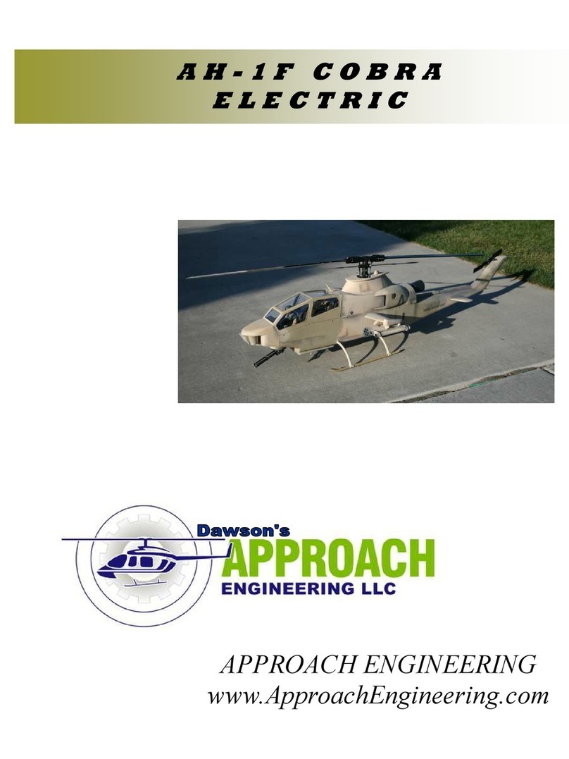
Approach Engineering AH-1F Cobra Electric User manual

APPROACH ENGINEERING
WWW.APPROACHENGINEERING.COM
PROUDLY MADE IN THE USA
AP101
AH-1F COBRA 600

AH-1F COBRA 60 PAGE # 2
APPROACH ENGINEERING
AH-1F 60 MECHANICS
1.0 Purpose
To establish a process that ensures control and standardization in the manufacturing of AH-1F Cobra for use with 60 size
mechanics. P/N AP-101.
2.0 Tools Required
Note: (A) denotes tools required for assembly and
(T) denotes tools required for testing.
Basic Hand Tools (A, T)
Epoxy 30 Minute, JB WELD (A)
Cyanoacratulate (CA) (A)
3.0 Reference Documents
Plans for AH-1F Cobra Plan Sheet (A, T)
4.0 Attachments
5.0 Introduction
1. WARNING This aircraft is not a toy. It is capable of serious bodily harm and property damage. Every precaution
must be taken to properly build this kit and install all radio components. It is your responsibility alone to ensure all
safety steps are taken outlined in the Academy of Model Aeronautics safety codes. If this is your first time building a
aircraft kit it is highly recommended that you find experienced help for the first flights. Consult your local hobby shop
or write to the AMA for further guidance.
Academy of Model Aeronautics
5151E. Memorial Drive
Muncie, IN 47302 (800) 435-9262
2. Please inspect all parts before building. If any parts are broken or missing please feel free to call or write for replace-
ment. All instruction manual photos are included with the CD along with other scale documentation pictures to ease in
finishing. If a step or photo appears unclear to you inspect the CD for additional photos with different views to aid in
assembly If you have any questions, comments, or improvements please call or write to:
Approach Engineering LLC
Ridgecrest, CA. 93555
3. We as manufacturer can provide you with assistance and a top quality kit and instruction manual. When built light,
straight, and true you will have a model that flies as well as it looks on the ground. However the finished product de-
pends on the quality built into it. We can not guarantee the flight performance. Take your time and read all instruc-
tions carefully before and during construction.
4. During the assembly procedure the use of the term CA refers to thin CA glue and CA+ refers to medium viscosity glue.

AH-1F COBRA 60 PAGE # 3
APPROACH ENGINEERING
AH-1F 60 MECHANICS
6.1 Assemble the side frames, (S-1, S-2, S-3, S-4) over a piece
of wax paper. Refer to the full size plans and the included pic-
ture for assembly. Punch out the four 3/32” fuselage side pieces
for each side. The provided tabs allow for proper alignment and
assembly of the fuselage sides. Build a right and a left taking
note of the triangle stock reference lines. These will aid in the
installation of the triangle stock. Using the notches provided
assemble and glue with CA the two fuselage sides.
6.2 Place the completed assemblies of the fuselage side frames
and lay them out to build a right and left half. Have the triangle
reference lines up so that they will be on the inside of the as-
sembly. The notches in the fuselage for F-3 and F-4 will line up
with the notches in the fuselage doublers. Using 30 minute ep-
oxy glue on the fuselage doublers. Set aside and allow to dry.
6.3 Take note of the laser labeled 3/4” triangle stock reference
lines on the inside fuselage surface. Cut and glue with CA the
3/4” triangle stock to match the reference lines. Complete for
both left and right sides.
6.4 Glue F-3, with the text and curved edge, and F-4 into the
notches of the fuselage doublers to make the fuselage box.
6.5 Glue 3/4” balsa triangle stock along the lower edge in front
of F-2 so that it extends past the front of the fuselage sides by
about 1/8” to be sanded off later. To aid in bending you may
want to saw cuts down to about 1/8” from the fuselage side.
6.6 Punch out former F-1 from the 1/8” light ply. Using CA
glue to the front of the fuselage so that the notches fit in the
fuselage sides. Sand the triangle stock flush with F-1.
6.0 FUSELAGE ASSEMBLY
Align Notch Openings
F-3
F-4
3/4” Triangle Stock
Saw Cuts
Notches Sand Flush
3/4” Triangle Stock

AH-1F COBRA 60 PAGE # 4
APPROACH ENGINEERING
AH-1F 60 MECHANICS
6.7 Punch out the 1/8” Light ply former F-2. Glue it behind F-
1 so that it is flush with the canopy edge.
6.9 Glue with epoxy the 1/4” light ply fuselage base so that it
is lined up with the back end of F-4 and front of F-3.
6.11 Punch out the 1/8” light ply transmission back plates and
canopy backer plate. Sand the outside corner edge to relieve the
corner so that the transmission and canopy will slide in easier.
Making sure not to get glue inside the canopy teeth area glue
TBT so the notch lines up with F-4. Glue the CBT in front of
the transmission backing. Complete for both sides.
6.8 Turn the fuselage assembly over. Using epoxy glue the
3/4” square hardwood landing gear blocks into the notches of
the fuselage doublers. The holes in the fuselage side should line
up with the landing gear mount holes.
6.10 Punch out the 1/8” light ply FD-2. Using CA glue in
front of F-2 and notched into F-1. Complete for both sides.
NOTES:
6.0 FUSELAGE ASSEMBLY
FD-2
TBT
CBT

AH-1F COBRA 60 PAGE # 5
APPROACH ENGINEERING
AH-1F 60 MECHANICS
7.1 Punch out the two 1/8” lite ply vertical fin supports and two
tail rotor tube supports (TSR) and one trailing edge former (TE-
2). The rounded edge of the tail rotor tube support faces fore-
word. Glue TE-2 in the upper slot and the two TSR supports in
the mid and lower slots.
7.3 Glue ¼” triangle stock to the inside edge of the vertical fin
supports and the tail rotor frame base.
7.5 Roughen the tail rotor tube surfaces with sand paper to
increase the strength of the glue bond.
7.2 Glue the vertical fin assembly into the tail rotor frame base
(TFB).
7.4 Referring to the plans for proper placement, glue in the tail
rotor drive shaft tube supports at 5.2” and 2.5” inches from the
bottom of the tube. The last support will be flush with the bot-
tom of the tube. Mark up a scrap piece of balsa at the correct
dimensions to help insert the supports at the right distances.
7.6 Using epoxy glue the tail rotor tube so that the bottom sur-
face is flush with the lower surface of the bottom tail rotor tube
support.
7.0 VERTICAL FIN ASSEMBLY
Flush with lower
surface

AH-1F COBRA 60 PAGE # 6
APPROACH ENGINEERING
AH-1F 60 MECHANICS
7.7 Trial fit the leading edge supports (TSF) to ensure proper
fit and contact with the tail rotor tube. Using epoxy, glue the
tail rotor leading edge supports in the notches and to the tail
rotor tube.
7.9 Apply epoxy to the inside surface of the tail rotor drive
shaft supports. Slide the tail rotor drive shaft starting from the
bottom up to the top surface of the upper drive shaft washer.
7.11 Apply ¼” triangle stock along the edge of the lower sur-
face of the tail rotor frame to the fuselage sides. Do not have the
triangle stock extend past the 3/4” triangle stock.
7.8 Slide the tail rotor pushrod outer housing through the holes
in the leading edge supports so that it so that it extends past the
upper leading edge support. You can trim later as necessary to
fit your control linkage setup.
7.10 Glue the tail rotor tube assembly to the fuselage assembly
by aligning the notches in the fuselage sides. Trim the triangle
stock as necessary to clear the pushrod tube.
7.12 Make two sets of the tail boom filler blocks by gluing
two (FBS) together. The tail boom filler blocks are made to fit
on the lower surface and back side of the tail rotor frame for
extra support and the outer profile will match the fuselage pro-
file. Using CA glue flush with the lower tail rotor frame sur-
face, back side of the tail rotor frame, and fuselage side surface.
7.0 VERTICAL FIN ASSEMBLY
TSF
Align in the notches
2 Sets of 2

AH-1F COBRA 60 PAGE # 7
APPROACH ENGINEERING
AH-1F 60 MECHANICS
7.13 Sand the tail filler block middle (FBM) at a angle and
trial fit to the remaining gap in the tail boom end. The block
should be tapered to a edge on the trailing side and the full ¼”
on the leading side.
7.15 Using the 3/32” x 6” wide x 12” long balsa, cross sheet
the remainder of the lower tail boom starting from the ¼” light
ply base to the end of the tail boom. Note: make sure not to
build a twist into the tail boom as you apply the cross sheeting.
7.17 Sand the horizontal fin to the desired shape. Note: the
real aircraft has a flat top and a rounded lower surface. This
may pull the nose up in foreword flight and it is up to the mod-
eler which shape to sand.
7.14 Glue the tapered filler block into position when properly
fitted in place.
7.16 Making two sets glue the upper and lower horizontal fins
together, from the ¼” balsa, making sure to make a right and a
left.
7.18 Glue the ¼” x ¼” x 7” spruce in the notch of ONE of the
horizontal stabilizers.
7.0 VERTICAL FIN ASSEMBLY
Tapered Edge
Leave 1/4” thick on this end
Filler Block

AH-1F COBRA 60 PAGE # 8
APPROACH ENGINEERING
AH-1F 60 MECHANICS
7.19 Note: depending on your desired finishing technique you
may want to omit permanently gluing the horizontal fins on at
this time to aid in sanding and finishing. Slide the spruce notch
in through the holes and have the fin tab notch fit in the side of
the fuselage. Trial fit the other fin and when satisfied glue with
CA+.
7.21 Assemble the servo mounting rails by punching out the
two 1/8” light ply supports labeled Approach Engineering. Pull
out the two 1/4” x 1/2” spruce servo rails and slide into place.
Do not glue at this time until you have properly fit the assembly.
7.23 Punch out the 1/4” balsa pushrod support. Glue the sup-
port to the pushrod outer tubing so that it properly lines up with
your servo position. Using scrap balsa properly secure the re-
mainder of the pushrod tube to the lower and side surfaces so
that there is as little movement as possible.
7.20 Glue ¼” by ¼” by 3” balsa along the tail rotor drive shaft
tube to the lower sheeting. Make sure to align the drive shaft as
straight as possible. Apply glue between the supports and the
tail rotor drive shaft.
7.22 Slide the assembly just behind F-4 between the fuselage
doublers and sitting on top of the 3/4” triangle stock along the
lower surface. Temporarily install a servo to help determine
proper pushrod placement.
7.24 Punch out the 1/8” light ply former F-5. Trial fit into
place behind F-4 in the transmission area. This is used to
square up the tail and to make more rigid. Fit in place with the
“Front” text facing toward the front of the aircraft. Fit into
notches and make sure it is flush with the upper fuselage edge.
in the fuselage side and glue in place.
7.0 VERTICAL FIN ASSEMBLY
Scrap Balsa
Pushrod Support
Notch

AH-1F COBRA 60 PAGE # 9
APPROACH ENGINEERING
AH-1F 60 MECHANICS
8.1 Sand the face of the fuselage assembly flush with F-1.
Glue on the two TSU back plates (TSU-B) together. Position
the notch toward the bottom of the fuselage and glue flush with
the bottom and sides of the fuselage nose.
8.3 Glue the two TSU bottom pieces, TSU-L, together. Mark
a line 1/2” from the back edge as a sanding guide. Sand the
TSU bottom pieces from the line at a constant angle to about
3/32” up from the rounded edge as shown in the picture.
8.5 Glue the five nose blocks together starting from NB-1 on
the bottom to NB-5. Make sure that the back edge is flush and
forms a block. Glue the assembly to the top of the TSU back
plate against F-1. Sand the nose blocks flush with the top of
the cross sheeting on the fuselage nose. Sand a small radius on
the front of the nose block and the sides flush.
8.2 To aid in sanding draw lines on the lower surface and the
fuselage side ¾” from the sheeting. When sanding make a even
transition from line to line. Sand the fuselage corners to their
finished rounded shape. Sand rounded corners on the three out-
side edges of the TSU back plate.
8.4 Glue the TSU bottom pieces into the notch in the TSU
back plate.
8.6 Make two sets of three T-2’s glued together. Sand the
front of the TSU to the desired finished rounded shape by
rounding the corners. Glue one T-1 between the two TSU as-
semblies and one T-3 on each side and sand the glued assembly
to the desired finished shape.
8.0 NOSE AND TSU (TELESCOPING
SIGHT UNIT) ASSEMBLY
Fuselage Bottom
Back Edge Flush
3 T-2’s
T-1 T-3
T-3

AH-1F COBRA 60 PAGE # 10
APPROACH ENGINEERING
AH-1F 60 MECHANICS
9.1 Punch out the 3/32” balsa canopy sides and the 1/8” lite
ply canopy guide teeth (CGT). Lay out the parts to build a right
and a left canopy side. Position the canopy guide teeth so that
the teeth extend past the bottom surface and match the bend
with the sides and equal 1/8” from ends. Glue with CA. cut
1/4” triangle stock (TRI-4) to fit between C-1, C-2, and C-3.
Line up the triangle stock with the printed reference lines.
9.3 When the glue has dried run a bead of glue up the remain-
der of C-1, C-2 and C-3. Using masking tape pull the canopy
sides to conform with the curve of C-1, C-2 and C-3. Sand the
top of the triangle stock flush with the canopy sides for cross
sheeting.
9.5 Carefully cut out the canopy top surface CT-1 from the
3/32” balsa. Glue on the top surface so that the front edge lines
up with the bend in the center canopy. Sand the canopy surface
flush with the center canopy surface.
9.2 Starting at the base, glue only 1” up on both sides of C-1,
C-2 and C-3 to the fuselage side and guide teeth. This will help
to build a straight canopy by first assembling it as a “box” struc-
ture.
9.4 Turn the canopy over and glue C-4 into place in the
notches in the canopy guide teeth. The bottom surface should
be flush with the edge of the canopy guide teeth.
9.6 Cut out the canopy center section CT-2 and complete the
step as earlier. Sand the front and rear edges flush as before.
Cut out the front canopy edge, CT-3 from the 3/32” balsa.
Align the front edge with the front of the canopy. Glue in place
with CA. When set sand the
back edge flush with the top
surface of CT-2.
9.0 CANOPY ASSEMBLY
Triangle Stock
extends past
upper edge.
Sand Flush
C-4
Sand this edge
flush
CT-2
CT-3

AH-1F COBRA 60 PAGE # 11
APPROACH ENGINEERING
AH-1F 60 MECHANICS
10.1 Punch out the 3/32” transmission sides and the 1/8” lite
ply transmission guide teeth (TGT). Making sure to build a left
and a right side, position the guide teeth so that the inside line of
the guide teeth line up with the bottom of the transmission sides
(detail A). The back edge (detail B) and the front edge (detail
C) will be lined up with the transmission side edges. Using CA,
glue the guide teeth along the bottom edge of the transmission
sides.
10.3 Glue 1” of the lower surface of E-1 to the transmission
sides. Glue the ¼” transmission sub base, TSM, to the upper
rear of the transmission sides. Once square, glue the remaining
sides of E-1 to the transmission sides.
10.5 Punch out the ¼” transmission mid blocks and trans top
and glue each set together making sure to have both ends la-
beled back together. Glue with CA.
10.2 Cut and glue 2” long by 1” triangle stock to the upper
edge of the transmission sides just in front of the intake open-
ings.
10.4 Turn the transmission assembly over and apply 1” trian-
gle stock to the edge of the fuselage sides and the transmission
sub base.
10.6 The transmission sub block will aligned with the back
edge of the transmission sub base. The transmission sides must
be pulled out to match the edge of the transmission mid block
assembly. Glue to the upper surface of the transmission assem-
bly. Position the trans top blocks directly over the mid blocks
and glue in place with CA.
10.0 ENGINE AND TRANSMISSION
BAY ASSEMBLY
TSM
E-1
1” Triangle Stock
Trans Mid Blocks
Trans Top Blocks
C B
A

AH-1F COBRA 60 PAGE # 12
APPROACH ENGINEERING
AH-1F 60 MECHANICS
10.7 Cross sheet the remainder of the transmission top with
3/32” balsa. There are 3/32” x 6” x 12” sheets included for the
sheeting.
10.9 For ease of sanding the intakes must be shaped prior to
gluing to the transmission assembly. Using intake template 1,
from the provided sticker paper, shape the front of the intakes.
Apply the adhesive template to both sides of the intake and sand
the intake to the template shape.
10.11 Using intake template 2 apply to the rear end of the
engine cowling side. There should be a 1/8” edge left on the
rear of the cowling side. Sand the cowling side to match the
profiles.
10.8 Making sure to build a left and a right engine intake posi-
tion the ¼” intake sub mounts (ESB) on the ¼” intake sides.
Glue with CA.
10.10 Sand the center portion of the intake to a rounded
shape. Only sand the edge between the intake sub mounts.
10.12 Apply the intake template 3 over the supplemental air
intake on the cowling sides. This is a template to aid in sanding
the intake angle. Sand a flat surface to the inside edge.
10.0 ENGINE AND TRANSMISSION
BAY ASSEMBLY

AH-1F COBRA 60 PAGE # 13
APPROACH ENGINEERING
AH-1F 60 MECHANICS
10.13 Flip the assembly over and apply the same angled sur-
face on the inside back edge of the supplemental intake.
10.15 Glue the cowling sides to the transmission assembly.
10.17 Sand the upper surfaces of the transmission assembly to
the desired rounded finished shape. Use the provided picture
below and the pictures provided on the disk to aid in sanding to
the finished shape.
10.14 Sand a rounded profile along the lower edge only of the
cowlings.
10.16 Glue E-2 on the back of the transmission assembly us-
ing the provided notches. Mark the profile that it will create on
the back surface. Mark the line 3/32” outside E-2 to account for
the cross sheeting that will be applied later.
10.18 Temporarily install the transmission bay assembly onto
the fuselage. Using the 3/32” x 6” x 12” balsa, cross sheet the
top of the tail boom starting behind the notches in the fuselage
side. The sheeting will go all the way around the vertical fin
and on top of the tail boom fillers.
10.0 ENGINE AND TRANSMISSION
BAY ASSEMBLY
Sand Lower Edge Only
Start sheeting at
notches
Sheet behind the
vertical fin

AH-1F COBRA 60 PAGE # 14
APPROACH ENGINEERING
AH-1F 60 MECHANICS
10.19 Keeping the transmission assembly. Punch out the 1/8”
light ply exhaust mounts, EXM, and exhaust former E-3. Using
the provided notches fit the mounts and former together to
achieve the required angle of E-3. The rounded surface of the
mounts should face up. Glue with CA.
10.21
10.23.
Notes:
10.20 Apply the doghouse template to the top of the transmis-
sion by putting the tip of the template 3-1/2” from the back edge
of E-3. Punch out the 3/32” doghouse templates, DH-1, and
glue around the template on the top of the transmission bay.
10.22
10.24
Notes:
10.0 ENGINE AND TRANSMISSION
BAY ASSEMBLY

AH-1F COBRA 60 PAGE # 15
APPROACH ENGINEERING
AH-1F 60 MECHANICS
10.25 Cut out the bottom edge of the vacuum formed dog-
house to match the profile of the upper surface of the transmis-
sion assembly
10.27 Carefully cut out the two transmission guide edges, DH-
1, from the 3/32” balsa sheet. Using CA+ glue just inside the
line marked on the previous step.
10.29 Glue the doghouse on the top of the transmission as-
sembly using CA+. Punch out the 1/4” balsa doghouse top and
position it over the doghouse. Draw the inner circle location
onto the vacuum formed doghouse and cut out.
10.26 Place the trimmed doghouse on the transmission assem-
bly and trace the outside contour onto the transmission.
10.28 Using a knife, razor, or Dremel cut out the material
between the doghouse edge pieces. Trim away any excess balsa
inside the transmission assembly.
10.30 Sand the doghouse top to the finished rounded shape
and glue in place.
10.0 ENGINE AND TRANSMISSION
BAY ASSEMBLY

AH-1F COBRA 60 PAGE # 16
APPROACH ENGINEERING
AH-1F 60 MECHANICS
11.1 Punch out the 1/8” lite ply wing spars and the 3/32” wing
ribs W-1, W-2, and W-3. Assemble them according to the plans
and glue the ribs to the wing spar. Glue on the ½” leading edge
stock centered on each wing spar leaving 3/32” on the upper and
lower surfaces for sheeting.
11.3 Apply CA to the wing ribs and wing spar. Bend the
cross sheeting over to match the contour of the wing ribs. Note:
wetting the wood will aid in bending. Sand the cross sheeting
trailing edge to match the wing rib contours.
11.5 Apply CA to the wing ribs and wing spar. Bend the cross
sheeting over to match the contour of the wing ribs. Note: wet-
ting the wood will aid in bending. Sand the cross sheeting trail-
ing edge to match the lower wing surface. Sand the leading
edge to match the upper and lower wing sheeting and round to
desired shape.
11.2 Using the laser cut 3/32” lower wing sheeting, sand a
small angle to the leading edge to match the angle of the leading
edge. Apply CA to the front of the sheeting and glue to the
leading edge.
11.4 Using the laser cut 3/32” upper wing sheeting, sand a
small angle to the leading edge to match the angle of the leading
edge. Apply CA to the front of the sheeting and glue to the
leading edge.
11.6 Apply epoxy to the wing root surface. Slide the protrud-
ing end of the wing spar into the slot in the fuselage side and
glue in place. Depending on finishing techniques you may want
to wait until later to glue in place.
11.0 WING ASSEMBLY

AH-1F COBRA 60 PAGE # 17
APPROACH ENGINEERING
AH-1F 60 MECHANICS
11.7 From the inside apply ¼” triangle stock to the edges of
the wing spar for increased strength. Note: picture shows wing
after a painted state for desired finishing technique.
CONTINUE TO NEXT SECTION.
NOTES:
11.0 WING ASSEMBLY

AH-1F COBRA 60 PAGE # 18
APPROACH ENGINEERING
AH-1F 60 MECHANICS
12.0 Rocket launchers can be assembled with 7 or 19 missile
tubes … We supply both Ply Ends for these so make sure to
choose one or the other depending on the model you are build-
ing.
12.2 Punch out the 1/8” lite ply rocket launcher stabilizers
(RLS) and the ¼” balsa rocket pylons. Make two sets of two
rocket launcher pylons.
12.4 Punch out the 1/8” lite ply rocket stabilizers, RLP, and
glue in the provided slots. You may glue the rocket launcher
tubes to the stabilizers at this time depending on your finishing
technique. It is recommended that you finish the pylons and
tubes prior to gluing.
12.1 Punch out the 1/8” lite ply rocket launcher faces. Glue in
each face flush with the rocket launcher tubes.
You need to make sure that the faces are properly aligned to
minimize tube twist.
12.3 Sand the rocket launcher pylons to the desired finished
shape.
12.5
Notes:
12.0 ROCKET LAUNCHER ASSEMBLY

AH-1F COBRA 60 PAGE # 19
APPROACH ENGINEERING
AH-1F 60 MECHANICS
13.0 Punch out four ¼” balsa wing tips (TLS), and two ¼”
balsa wing tips centers (TLC). Glue one balsa wing tip center
on each side of the wing tip center. Make two launchers total at
the same time.
13.2 Slide the 1/8” tow supports into the slots of the wing tip
assembly. Glue in place with epoxy to allow you time to prop-
erly position the supports.
13.4 Pull out the smaller TOW tubes and slide them into
place. Run a small bead of CA along the inside edge of the tube
and allow to dry.
13.1 Sand the wing tip assembly to the desired finished shape.
13.3 Glue the 1/8” tow holders on the notches on the front of
the TOW assembly.
NOTES:
13.0 TOW LAUNCHER ASSEMBLY

AH-1F COBRA 60 PAGE # 20
APPROACH ENGINEERING
AH-1F 60 MECHANICS
14.1 The 20mm gun can be made to rotate with the use of a
servo. Parts are included for this option. Punch out the 1/8” lite
ply gun base, gun side supports, and gun supports. Glue the gun
supports into the notches of the gun base.
14.3 Prepare the three ¼” diameter wood dowels by drilling a
3/32” hole in the end. The barrels then need to be tapered. One
easy method is by putting the back end in a drill bit and spin-
ning it while a helper sands it.
14.5 Glue the three barrels into the gun base so that the ¼”
dowels are flush with the ends. Punch out the front and middle
barrel support from the 1/8” ply and slide into place. Use a
small amount of CA to glue in place. Paint and finish the gun
turret to finished appearance.
14.2 Using 1/16” balsa, cross sheet the gun supports. Run the
grain perpendicular to the gun side supports. Use a small
amount of water to wet the balsa to aid in bending.
14.4 Glue in the gun side supports in the notches in the gun
base. Slide in the ¼”diameter balsa sticks into the hole of the
gun side supports and sand flush. Punch out the two ¼” balsa
gun chin blocks (GCB) and glue together. Sand the chin blocks
down to a feather edge on one side in order to achieve the
proper angle.
14.6 Referring to the plans position the gun chin blocks to the
lower nose cross sheeting and mark the position. Glue the
feathered down balsa gun chin blocks to the bottom surface.
Using a 5/16” drill bit or knife, cut out the bottom sheeting
through the provided hole in the gun chin blocks.
14.0 20mm CANNON ASSEMBLY
Other manuals for AH-1F Cobra Electric
1
Table of contents
Other Approach Engineering Toy manuals
Popular Toy manuals by other brands

REVELL
REVELL Junkers Ju-87 B2/R2 Stuka Assembly manual

Our Generation
Our Generation Campfire Cookout BD35152 quick start guide

REVELL
REVELL PzKpfw V Panther Ausf G Assembly manual

The Wings Maker
The Wings Maker FAIRCHILD PT-26 40 instruction manual

BNF
BNF Blade 300 X instruction manual

MiniArt
MiniArt WW II Military Miniatures Series General Instruction