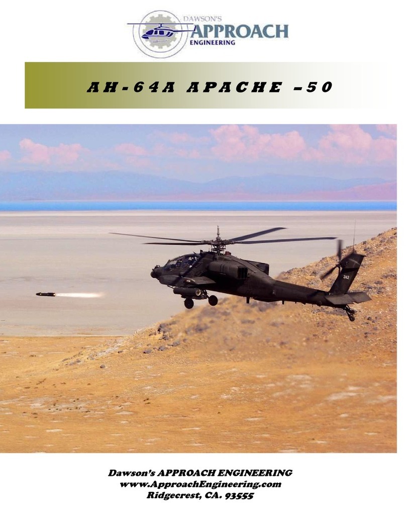
Approach Engineering AH-64A APACHE SWIFT/LOGO 10 User manual

A H - 6 4 A A P A C H E
S W I F T / L O G O 1 0
APPROACH EGIEERIG
www.ApproachEngineering.com

APACHE-E SWIFT/LOGO10 PAGE # 2
DAWSON’S
APPROACH EGIEERIG
AH-64A ELECTRIC
1.0 Purpose
To establish a pro ess that ensures ontrol and standardization in the manufa turing of AH-64A Apa he for use with ele -
tri Swift and Logo 10 size me hani s. P/ AP-103.
2.0 Tools Require
Note: (A) denotes tools required for assembly and
(T) denotes tools required for testing.
Basi Hand Tools (A, T)
Epoxy 30 Minute (A)
Cyanoa ratulate (CA) (A)
3.0 Reference Documents
NA
4.0 Attachments
5.0 Intro uction
1. WARIG This air raft is not a toy. It is apable of serious bodily harm and property damage. Every pre aution
must be taken to properly build this kit and install all radio omponents. It is your responsibility alone to ensure all
safety steps are taken outlined in the A ademy of Model Aeronauti s safety odes. If this is your first time building a
air raft kit it is highly re ommended that you find experien ed help for the first flights. Consult your lo al hobby shop
or write to the AMA for further guidan e.
A ademy of Model Aeronauti s
5151E. Memorial Drive
Mun ie, IN 47302 (800) 435-9262
2. Please inspe t all parts before building. If any parts are broken or missing please feel free to all or write for repla e-
ment. All instru tion manual photos are in luded with the CD along with other s ale do umentation pi tures to ease in
finishing. If a step or photo appears un lear to you inspe t the CD for additional photos with different views to aid in
assembly If you have any questions, omments, or improvements please all or write to:
Approa h Engineering LLC
Ridge rest, CA. 93555
3. We as the kit manufa turer an provide you with assistan e and a top quality kit and instru tion manual. When built
light, straight, and true you will have a model that flies as well as it looks on the ground. However the finished produ t
depends on the quality built into it. We an not guarantee the flight performan e. Take your time and read all instru -
tions arefully before and during onstru tion.
4. The fuselage does not require to be built over the top of plans. It is designed with tabs and slots to build the fuselage
straight. The appendix has exploded view drawings to help identify the parts.
5. During the assembly pro edure the use of the term CA refers to thin CA glue and CA+ refers to medium vis osity glue.

APACHE-E SWIFT/LOGO10 PAGE # 3
DAWSON’S
APPROACH EGIEERIG
AH-64A ELECTRIC
6.1 Pun h out one Verti al Frame, VF-1 and supports VF-2,
and VF-3 from 1/8” plywood. Glue the ross members, VF-2,
into the slots of the verti al frame sides and VF-3 on top. Make
sure that all parts are square for a straight verti al fin.
6.2 Pun h out the verti al fin base, F-6, from 1/8” light ply.
Glue the verti al fin base onto the verti al fin assembly.
6.3 Assemble ea h pulley idler assembly by inserting the bear-
ings through a guide washer then into ea h idler pulley. The
flanges should fa e out. Slide the 1/8” x 1.062” steel shaft
through ea h assembly.
6.4 Pull out the inje tion molded pulley bushings and pla e
one on ea h side of the assembly.
6.5 The belt will be assembled between the two pulley assem-
blies. Fit the pulley assemblies into pla e with the toothed pul-
ley in the lower hole and the smooth pulley in the upper hole.
The belt should be pla ed so that the flat side is against the
smooth pulley. Do not glue the assemblies at this time.
6.6 Pull out the larger diameter tail boom se tion and trial fit
into pla e. Slightly roughen the surfa e where it is supported by
the frame. Pun h out three verti al fin leading edges, VF-4,
from 1/8” light ply. Using epoxy glue the tail boom se tion to
the assembly so that the lower edge is flush with the lower sur-
fa e of the lower support and the slotted end is fa ing up.
6.0 VERTICAL FI FRAME
ASSEMBLY
Bearings 2 ea h
Guide Washers 2 ea
VF-1
VF-2
VF-3
Bearing
Shafts
Smooth
Pulley
Note dire tion of teeth
VF-4
Flush with lower
Surfa e

APACHE-E SWIFT/LOGO10 PAGE # 4
DAWSON’S
APPROACH EGIEERIG
AH-64A ELECTRIC
6.7 Pun h out the 1/8” light ply verti al fin spa er, VFS. Glue
the spa er on the inside edge of the verti al fin side so that the
hole is properly aligned.
6.8 Assemble the bell rank by positioning it against the
spa er. Slide the bell rank shaft through the bell rank spa er
and the bell rank. At this time you may want to assemble your
ontrol horns to the bell rank. The bell rank shaft should be
flush with ea h outside edge of the verti al fin sides.
6.9 Using the short pushrod wire onne t it to the levis so that
the wire goes through the enter of ea h of the verti al fin lead-
ing edge supports.
6.10 Pun h out the two verti al fin doublers, VFD, from the
1/8” light ply sheet. Glue one doubler to ea h side of the verti-
al fin sides. This will hold in the pulley assemblies and bell-
rank shaft.
6.0 VERTICAL FI FRAME
ASSEMBLY
6.11 Pun h out the 1/8” light ply former F-7. Using CA glue
it onto the verti al fin assembly using the provided not h.
6.12 Pun h out the three ea h upper tail boom fillers from
1/4” balsa. Make two sets of filler assemblies by gluing three
ea h together. Set aside with the verti al fin assembly for the
fuselage assembly.
3/16” x .560” brass spa er
5/32 x 1.06”
Bell rank
shaft
VFD

APACHE-E SWIFT/LOGO10 PAGE # 5
DAWSON’S
APPROACH EGIEERIG
AH-64A ELECTRIC
7.1 Assemble the side frames, S-1 and S-2, over a pie e of
wax paper. The fuselage side is made up of two separate pie es.
The provided tabs allow for proper alignment and assembly of
the fuselage sides. Put the tabs together and apply a small
amount of CA to the joints.
7.2 Pla e the ompleted assemblies of the fuselage side frames
and lay them out to build a right and left half. The text writing
should be fa ing up. Build up the fuselage side to have the bay
ut-out on your desired side. Using 30 minute epoxy glue on
the fuselage doublers by aligning the ut outs on the doublers
and the fuselage sides. Set aside and allow to set.
7.3 Using the laser referen e lines apply 3/4” triangle sto k to
the inside edge of the fuselage sides. Pun h out the 1/4” lower
tail boom filler, LTF, and glue to the lower rear edge of the fu-
selage assembly. Glue the Upper tail boom assembly, text fore-
word, from the
previous se -
tion.
7.4 Pun h out F-1, F-2, and F-5 and pull out the two me han-
i s mounting rails. For the swift, assemble the me hani s
mounting rails to fit your me hani s by using the appropriate
labeled ut outs in the fuselage doublers. Glue with CA.
7.5 Using the 1/4 light ply fuselage bottom and glue into pla e
on the bottom of the fuselage. Make sure that the labeling for
front is fa ing foreword.
7.6 Trial fit the verti al fin assembly into the tail. On e satis-
fied glue the verti al fin assembly into the not hes provided
while making sure not to build a twist into the tail boom.
7.0 FUSELAGE ASSEMBLY
PROCEDURE
S-1
S-2
S-1
S-2
Bay Opening
3/4” Tri
Lower Tail boom Filler
Upper Tail
Boom Filler
Assembly
F-5
F-2
F-1

APACHE-E SWIFT/LOGO10 PAGE # 6
DAWSON’S
APPROACH EGIEERIG
AH-64A ELECTRIC
7.7 Pun h out the two 1/4” balsa verti al fin filler, VFF. Glue
one to ea h side of the verti al fin assembly up against the up-
per tail boom filler so that it is fully seated on the fin and flush
with the top surfa e.
7.8 Install the 36” tail rotor ontrol tube by sliding it through
the holes in F-2 and F-5. Pun h out the 1/4” balsa ontrol tube
mount, CTM, and set to the proper height. The side to be glued
to the fuselage side is marked. It is best to onne t the inner
pushrod at this time for proper alignment. When satisfied glue
the outer tube to F-2 and F-5 using CA+.
7.9 Cut pie es of 1/2” triangle sto k to fit in the lower opening
below the verti al fin assembly. Note: prior to sheeting the
bottom surfa e you may desire to add servo ontrol to the hori-
zontal fin. The fin is designed to float freely in flight however
installing ne essary pushrods and ontrol horns now will be
easier at this point.
7.10 Pun h out the two horizontal fin doublers, HFB, and glue
to the inside edge of the verti al fin assembly. There is one for
ea h side and be sure to properly align the holes for the horizon-
tal fin.
7.11 Cross sheet the lower se tion of the fuselage using 3/32”
balsa sheet. Set the fuselage up square in order to not build a
twist into the fuselage. Starting from the aft se tion of the fire-
wall to the end of the tail boom.
7.12 Pull out the 5/16” diameter by 6.5” long Aluminum tube
and two 1/2” square hardwood main landing gear mounts. Slide
the brass tube through the gear blo ks. Epoxy the blo ks into
pla e so that they are flush with the outside fuselage side.
7.0 FUSELAGE ASSEMBLY
PROCEDURE
Control Tube
HFB
VFF
CTM
Control
Linkage
Assemble Flush

APACHE-E SWIFT/LOGO10 PAGE # 7
DAWSON’S
APPROACH EGIEERIG
AH-64A ELECTRIC
7.25 Pun h out the 3/32” balsa transmission ba king sheets,
TB-1 and TB-2, and the anopy ba king sheets, CB-1 and CB-2.
Align as ne essary and glue into pla e with CA+.
7.26 Pull out the two 1/2” square upper landing gear blo ks
with a 1/4” through hole. Epoxy the blo ks into the slots so that
the blo k is flush with the fuselage side. The other end of the
blo k will be flush with the inside edge of F-2. Glue triangle
sto k to the landing gear mounts.
7.27 For Logo me hani s glue ut the 3/8” x 3/4” hardwood
rails and epoxy into pla e a ording to the fuselage base. The
hardwood rails will need to be ut down 1/4” to fit on the fuse-
lage base.
7.28 Cut and glue 3/8” triangle sto k to both edges of the fuse-
lage bottom and the fuselage doublers.
7.29 Cut and glue 3/4” triangle sto k to fit between the fuse-
lage base and F-5. Complete for both inner sides.
7.0 FUSELAGE ASSEMBLY
PROCEDURE
CB-1
CB-2
T B-1
TB-2
1”x1/2” TRI
Sto k
1/4” Tri Sto k
3/8” Tri Stok

APACHE-E SWIFT/LOGO10 PAGE # 8
DAWSON’S
APPROACH EGIEERIG
AH-64A ELECTRIC
8.1 Pun h out the Nose Sides, NS-1, Nose Top, N-T, and Nose
Bottom, N-B from the ¼ in h balsa sheet. Make sure that the
nose side pie es have the labeling both up to make sure that the
nose top and bottom are glued on the right edgesGlue together
to form a open box as shown using CA+.
8.2 Pun h out the two nose filler blo ks, N-F, from the ¼”
balsa sheet. Note: the filler blo ks must be glued foreword to a
point so that when the nose is sanded they will be sanded flush
as well. As a approximate guide it will be about 3/16” from the
trailing edge. Glue on ea h inside lower orner with CA+.
8.3 Cut two 3/4” triangle sto k approximately 2.5” in length.
Glue in pla e so that they will overhang both the lower inside
orners of the nose so that when the front and ba k fa e are
sanded flat they will be flush as well.
8.4 Sand the front and the ba k of the nose se tion flat. For
best results lay a pie e of sandpaper on a flat surfa e and sand
the entire surfa e at the same time. Sand until all the darker
laser ut edges of the side pie es are sanded away.
8.5 Cut two ½” balsa triangle sto k approximately 2.5” in hes
in length. Glue in the upper inside edge of the nose assembly so
that the ends overhang the front and rear fa e to allow for sand-
ing. Sand the triangle sto k flush with the front and ba k sur-
fa es.
8.6 Pun h out the TADS/PNVS front plate, NS-F from the ¼”
in h balsa sheet. Note: for best s ale appearan e you an out-
line the profile of the front plate on the sanded front edge. Us-
ing the supplied pi tures sand the nose to the final shape. After
sanded glue ba k onto the front of the nose assembly.
8.0 TADS AD PVS
COSTRUCTIO
N-T
N-S-1
N-B
N-F
N-F

APACHE-E SWIFT/LOGO10 PAGE # 9
DAWSON’S
APPROACH EGIEERIG
AH-64A ELECTRIC
9.1 Pun h out two ea h of the foreword avioni s bay formers
F-3 and F-4 from the 1/16” balsa sheet. Glue them into their
respe tive slots on the outside of both of the fuselage sides
while making sure that they stay perpendi ular to the surfa e.
Pla e the main landing gear leg on ea h side of the tube.
9.2 Pun h out the foreword avioni s bay side, FAB-1, from the
1/16” balsa sheet. Note: Make sure to have the bay side with
the ut out on the same side as the fuselage side ut out. Align
and glue to the formers F-1, F-2, F-3, and F-4 using the not hes
provided and aligning the edges. Complete for both sides.
9.3 Pun h out the two ¼” balsa foreword avioni s bay base,
FAB-B. Glue the bay base into the not hes on both sides of the
lower edge of the fuselage side. The FAB base has the front
edge labeled.
9.4 Cross sheet the upper surfa es of the avioni s bays with
3/32” balsa. Complete for both left and right sides.
9.5 Glue the ompleted nose assembly to the front of the fuse-
lage. Make sure that the bottom edge is below the lower surfa e
of T-1 by 3/32” to a omidate the removable fuselage base to
be ompleted later.
9.6 Pun h out the twelve 1/4” balsa avioni s bay nose blo ks,
FAB-N. Make two assemblies by gluing together five ea h.
Using a marker draw the approximate shape to ea h FAB blo k
and sand to size.
9.0 FOREWARD AVIOICS
BAY COSTRUCTIO

APACHE-E SWIFT/LOGO10 PAGE # 10
DAWSON’S
APPROACH EGIEERIG
AH-64A ELECTRIC
9.7 Trial fit the FAB nose blo ks to the fuselage. Determine
the front edge and sand to a finished rounded shape. Glue to the
front of the avioni s bays.
9.8 Sand the lower edges of the nose assembly to mat h the
TADS front plate and the pi tures in luded on the CD,
9.9 Pun h out the two ¼” balsa foreword avioni s bay doors,
FAB-D. Make sure to build a right and a left side. Sand both
doors from a rounded dome shape in the enter to a tapered
feathered edge on the edges.
9.10 Cut a pie e of ¼” square balsa at a length of 3.8 in hes.
Glue to the bottom edge of the FAB door that will over the
opening to allow the ele troni s a ess. Hinge the working bay
door with supplied pinned hinges. The hinges should have the
slots ut along the 1/4” balsa edge going ba k at an angle.
9.11 Fit the door in pla e and make mat hing hinge slot uts
in the 1/4” balsa avioni s bay floor. The ends of the hinges may
be trimmed for appearan e. Do not permenantly glue the
hinges until after finishing.
9.12 The door an be glued shut permanently or an be used to
a ess plugs, swit hes, or for additional s ale detail.
9.0 FOREWARD AVIOICS
BAY COSTRUCTIO

APACHE-E SWIFT/LOGO10 PAGE # 11
DAWSON’S
APPROACH EGIEERIG
AH-64A ELECTRIC
10.1 Pun h out the two 3/32” balsa anopy sides. Pun h out
the two 1/8” plywood anopy guide teeth CGT. Sand the teeth
where they will be exposed down a little to smooth them out
and make a slight angle. Making sure to build a right and a left
side position the guide teeth so that the bottom, front, and rear
edges all are flush.
10.2 Pun h out the three anopy formers CF-1, CF-2, CF-3,
and CF-4 from 1/8” light ply. Using CA+ glue formers 1, 2,
and 3 into pla e. Glue CF-4 into the orner of the front anopy.
Take time and make sure to build a straight anopy.
10.3 Carefully ut out the anopy top, CT-1, from 3/32” balsa.
Making sure to build a straight anopy, glue the lower edge of
CT-1 to the front edge of CF-1. The anopy top will overhang
the front edge of the anopy. On e glued sand the upper anopy
surfa e and front edge flush.
10.4 Carefully ut out CT-2 from 3/32” balsa. Position and
glue the top sheeting so that the ba k edge is entered on the top
of the former CF-2. When gluing the anopy sides follow the
anopy top edge to build a straight anopy. The leading edge by
CT-1 will overhang and will be sanded flush with the anopy
surfa e.
10.5 Carefully ut out the pilot anopy top, CT-3, from 3/32”
balsa. Position and glue the anopy top to the assembly. Glue
the anopy sides to mat h the profile of the anopy top to build
a straight anopy.
10.6 Sand the anopy top sheeting flush to the anopy sides
and anopy front and ba k surfa es.
10.0 CAOPY COSTRUCTIO
Canopy Teeth
Sand Angle
Flush Edge
CF-3
CF-4
CF-2
CF-1
Sand edges flush
with surfa e
Line up bottom
edge
Ba k edge
Centered on the
Canopy former
Sand flush
Sand
Sand flush with
Canopy sides.

APACHE-E SWIFT/LOGO10 PAGE # 12
DAWSON’S
APPROACH EGIEERIG
AH-64A ELECTRIC
11.1 Pun h out the two transmission sides, T-1, from the 3/32
balsa sheets. Pun h out the two Transmission guide teeth, TGT,
from the 1/8” plywood. Lay the transmission side frames to
build a right and a left. Using CA+ glue the two transmission
guide teeth to the transmission side frames by aligning the edges
together at A and B as shown on the pi ture.
11.2 Pun h out T-1 and T-2 from the 1/8” plywood. Using
CA+ glue the transmission by aligning the T-2 bulkhead with
the not hes in the guide teeth. Only glue up the straight se tion
of the former and align with the front edge. Pun h out the 3/32
in h balsa ply Transmission Upper Frame. Using CA glue
along the top edge of the transmission side.
11.3 Pun h out the transmission top sheet, T-T, from the 3/32”
balsa sheet. The front edge of the top sheeting is not hed and
slides into the T-1 bulkhead. Align the sides of the transmission
sides with the edge of the top sheet. Glue with CA+.
11.4 From the parts bag get out two lengths of 1” triangle
sto k with a length of 2.5”. In the front top orner of the trans-
mission side and the T-1 glue the triangle sto k in pla e with
CA+ to allow sanding to the final shape.
11.5 Cut and sand the triangle sto k to mat h the inside profile
of the T-1 former.
11.6 Sand the orners of the transmission to mat h the profile
that is laser marked into the fa e of T-1. The top sanded profile
should mat h the upper transmission sheeting. This is the out-
line of the anopy
11.0 TRASMISSIO BAY
ASSEMBLY
A
A
B
B

APACHE-E SWIFT/LOGO10 PAGE # 13
DAWSON’S
APPROACH EGIEERIG
AH-64A ELECTRIC
11.7 Pun h out the two doghouse side pie es, DH-S, and dog-
house top, DH-T, from the 3/32 balsa sheets. Glue the dog-
house side pie es to the bottom of the doghouse top so the front
edge of the side is aligned with the orner of the top. Using
CA+ glue the doghouse assembly to the top of the transmission
so that the front edge of the top sheeting is flush with the front
fa e of T-1.
11.8 Sand the ba k of the transmission doghouse top sheeting
and upper transmission sheeting to mat h the angle of the trans-
mission. When finished sanded ea h sheeting should be sanded
to a feather edge whi h will allow ross sheeting.
11.9 Temporarily pla e the transmission on the fuselage. Glue
pie es of s rap balsa on the inside edge of the transmission
sides to hold the surfa es of the transmission and fuselage side
flush. Using some masking tape pull the sides of the fuselage
together to make sure that the sides are parallel for sheeting.
When satisfied sheet the top of
the transmission bay with 3/32”
balsa.
11.10 Cut out ½ in h triangle sto k 6.5 in hes long and glue
along the inside upper edge of the transmission side starting
behind T-2 to the trailing edge. This will aid in sanding a
rounded profile.
11.11 Install the transmission bay and anopy assembly ba k
onto the fuselage and make sure that the tape on the fuselage
still allows the sides to mat h up and for proper spa ing. When
satisfied butt the 3/32” sheeting up against the transmission bay
and ross sheet the top of the
tail boom.
11.0 TRASMISSIO BAY
ASSEMBLY
11.12 Continue ross sheeting the top of the tail boom to the
end of the tail boom. Cut away any sheeting by the tail rotor
ontrol pushrod for free movement.
S rap balsa for edge
alignment.
DH-T
DH-S
Tape

APACHE-E SWIFT/LOGO10 PAGE # 14
DAWSON’S
APPROACH EGIEERIG
AH-64A ELECTRIC
12.1 Pun h out the two 3/32 balsa Engine E-1, E-2, and the
two engine na elle side pie es EN-S. Note: E-1 is perpendi u-
lar to the transmission side where E-2 will be at a angle deter-
mined by the slots in the fuselage and na elle sides. Glue E-1
first perpendi ular to the side. Without gluing install E-2 and
the na elle side. When satisfied with the fit glue with CA+.
12.2 Turning the transmission assembly over to work on the
bottom of the engine na elles. Pun h out one ea h of the na-
elle sheeting, EN-1, for the bottom of ea h na elle. Align the
edges and glue in pla e with CA+.
12.3 Pun h out the lower na elle build up pie e, EN-2, and
glue it on the inside outboard lower orner of the engine na elle.
12.4 Glue the side engine na elle filler, EN-F, on top of EN-2.
Cut out a pie e of 3/4” by 1.5” triangle sto k. Round off one
end and glue in the front orner made by the two engine na elle
filler pie es.
12.5 Cut a length of ½ by 4.5” triangle sto k to fit along the
upper na elle outboard surfa e. The ends should mat h with the
formers.
12.6 Pun h out the ¼” balsa na elle fillers EN-3. Sand the
end to mat h the angle made by the former E-2. Glue in the
inside rear orner of the na elle so that the top is flush with the
former EN-4.
12.0 EGIE ACELLE
ASSEMBLY
E-1
E-2

APACHE-E SWIFT/LOGO10 PAGE # 15
DAWSON’S
APPROACH EGIEERIG
AH-64A ELECTRIC
12.7 Pun h out two for ea h of the na elle exhaust side EN-4.
Glue one on the top and bottom inside surfa e of the na elle
side so that their surfa es are flush with the top edge of the na-
elle side.
12.8 Sheet the top of the engine na elle by using the 3/32” ut
out EN-1. Glue in pla e with CA+.
12.9 Pun h out two engine nose blo ks, ENB, for ea h na-
elle. Make two sets of two blo ks by gluing two ea h together.
12.10 Making sure to build a right and a left, draw a line in
pen il about 3/8” around the enter hole to aid in sanding. Sand
the edge that will go up against the fuselage side to the rounded
s ale shape as shown. Sand the enter ir le to a radius rea h-
ing out to the line drawn. This prevents ompli ation in sanding
later. The other edges are sanded after it is glued to the front of
the na elles.
12.11 Position the engine nose blo k assemblies so that the
one sanded edge is up against the transmission side. Glue the
ompleted assemblies to the front of the engine na elles using
CA+.
12.12 Sand the outside upper and lower orners of the engine
na elle by first mat hing the shape of the nose blo k. The ra-
dius tapers off toward the end of the na elle. Round the nose
blo k into a rounded shape blending it into the na elle. Sand
the orner of the exhaust over EN-4 to a rounded shape.
12.0 EGIE ACELLE
ASSEMBLY

APACHE-E SWIFT/LOGO10 PAGE # 16
DAWSON’S
APPROACH EGIEERIG
AH-64A ELECTRIC
13.1 Pun h out six 1/4” balsa nose gearbox bodies, NGB-1.
Building a right and left sides glue three ea h together by align-
ing up all edges.
13.2 Lay out the assemblies to make a right and left gearbox.
Pun h out one ea h of the nose gearbox front, NGB-2, and glue
on the front of ea h gearbox mat hing the outside profile.
13.3 Turn the assemblies over to work on the ba k side. Us-
ing two ea h of ¼” balsa gearbox bases, NGB-3, glue on the
ba k enter of ea h gearbox.
13.4 Using the in luded air raft photos sand the gearbox to
it’s final sanded shape.
13.5 Pun h out the two 1/8” plywood engine intake swirl
vanes, EN-I, and sand to a desired finished shape. This is os-
meti purposes only. The blades may be shaped like propellers
to simulate the intake swirl vanes. Depending on the desired
finishing te hnique it is re ommended to glue in pla e later.
13.0 OSE GEARBOX
ASSEMBLY
13.6 Install the transmission bay assembly onto the fuselage.
Sand the ba k edge of the transmission bay to the final rounded
shape while blending it into the fuselage tail boom interfa e.
Sand the lower fuselage orners to the finished shape.
NGB-3
NGB-4

APACHE-E SWIFT/LOGO10 PAGE # 17
DAWSON’S
APPROACH EGIEERIG
AH-64A ELECTRIC
14.1 Note: The onstru tion of the engine exhaust is fairly
deli ate. Care should be taken not to put too mu h pressure on
the parts in the beginning stages. Instru tions show only build-
ing up one side. You may build both up simultaneously and are
inter hangeable for both right and left. Start by pun hing out
the engine exhaust base, EEX-1, and four exhaust sides, EEX-2.
Insert the sides into the base and glue in pla e with CA.
14.2 Using the engine exhaust base, EEX-1, position on top of
the sides so that all the not hes slide into pla e. Glue with CA.
Pun h out one ea h exhaust side rear EEX-3. Insert it into the
not hes next to the outside exhaust side. When in pla e glue
with CA.
14.3 Pun h out six ea h of the engine exhaust top, EEX-4,
from the 1/16” sheet. Three will go on top and three will go
underneath. Line up the rear exhaust edges and side edges.
They will be all equally spa ed. Complete for the top and bot-
tom.
14.4 Note: Take are with the parts used in this step be ause
they are deli ate. Using a razor blade, ut the rear exhaust
formers, EEX-5, out from the laser ut sheet. Glue three ea h
on the exhaust ports of the exhaust assembly by lining up the
edges.
14.5 Before final assembly sand, seal, paint, and fuel proof the
engine exhausts. Be sure to also fuel proof the inside of the
assemblies. Set these aside until final finishing where they will
be permanently glued.
14.6 Upon ompletion of the finishing of the transmission
bay, glue the engine exhausts to the ba k of the engine na elles.
14.0 EGIE EXHAUST
ASSEMBLY
EEX-1
EEX-3

APACHE-E SWIFT/LOGO10 PAGE # 18
DAWSON’S
APPROACH EGIEERIG
AH-64A ELECTRIC
15.1 Pun h out the 3/32” horizontal fin spar, HF-S, and hori-
zontal fin ribs H-2, and H-3. Glue the ribs to the spar in their
orresponding not hes.
15.2 Pun h out the 3/32” horizontal fin ribs H-1A, H-1B.
Glue the two H1-A ribs in the outside not hes fa ing toward the
front edge. H1-B ribs are glued to the inside not hes fa ing
toward the trailing edge.
15.3 Pun h out the horizontal fin lower sheeting, HF-1, and
pla e the spar assembly in the proper pla e. The wing spar will
line up with the enter sheeting ut out and be flush with the
edge. Start by applying CA+ to the lower surfa e of the spar.
On e dried apply CA+ to the lower surfa e of the ribs behind
the spar to the trailing edge. Press the sheeting up into pla e.
15.4 Pun h out the 1/16” balsa upper sheeting HF-2. Sheet
the top of the horizontal fin by aligning the trailing edge of the
upper and lower sheeting. Apply CA+ to the upper surfa e of
the spar, the ribs behind the spar and trailing edge. Press the
sheeting ba k and hold the trailing edge together.
15.5 Glue the upper and lower surfa es of the balsa leading
edge and press the sheeting down into pla e. Cut off the ex ess
sheeting along the leading edge. Using a flat sanding blo k
sand the leading edge flat.
15.6 Turn the horizontal fin assembly over to expose the box
bay. Pun h out the two ¼” light ply horizontal fin supports
HFS-1. Using CA+ glue the supports up against the upper
sheeting, H1-A, and the wing spar.
15.0 HORIZOTAL FI
ASSEMBLY

APACHE-E SWIFT/LOGO10 PAGE # 19
DAWSON’S
APPROACH EGIEERIG
AH-64A ELECTRIC
15.7 Cut two pie es of ½” leading edge sto k to fit the lead-
ing edge of the horizontal fin. Glue the leading edge sto k en-
tered on the leading edge with CA+. After finished sand the
leading edge to a rounded finished shape.
15.8 Viewing the horizontal fin from the bottom pun h out the
1/16” balsa horizontal fin enter, HFC. This will fit in the en-
ter trailing edge of the fin. Note: The HFC will be installed at a
angle therefore it is re ommended to sand the upper and lower
sheet surfa es at the same angle to reate a flat surfa e for the
HFC to be glued. When satisfied glue the HFC in pla e and
sand the edges flush with the upper and lower sheeting.
15.9 Working on the horizontal fin tips, pun h out the two ¼”
balsa pie es HFT. Glue on the fin tips making sure they are
entered on wing tip. Note, the horizontal fin tips are purposely
made larger to allow for sanding flush with the surfa es. When
omplete sand the upper and lower surfa es flush with the
sheeting and leading edge.
15.10 Sand the horizontal fin tips to a rounded finished shape
using the pi tures as a guide.
15.11 Pull out the two 1/4” by ¼” long brass tubes. Pun h
out the two lower horizontal fin supports HFS-2 from the ¼”
light ply sheet. Roughen up the outside surfa e of the brass
tubes with sandpaper. Glue the brass tubes into the half ir le
in the lower fin supports. Put into pla e and drill and ounter-
sink the holes. Temporarily install the s rews to he k the fit.
15.12 Depending on your s ale options you may finish the
horizontal fin to be rotated by a servo. With the use of a s rap
pie e of light ply and a ontrol horn you may ontrol the fin
with a spare hannel.
15.0 HORIZOTAL FI
ASSEMBLY
HFT

APACHE-E SWIFT/LOGO10 PAGE # 20
DAWSON’S
APPROACH EGIEERIG
AH-64A ELECTRIC
16.1 Start by pun hing out two ea h of the 1/8” plywood wing
spars, WS, and two ea h of the wing ribs, W-1, W-2, W-3, and
W-4. Making sure to build a right and a left slide the wing spars
into their respe tive pla e in the wing spars. Make sure that the
rib goes flush at the top and bottom surfa e of the wing rib.
Glue in pla e with CA.
16.2 Pun h out the two lower wing sheeting, WS-1, from the
1/16” balsa sheet. Line the inboard rib, W-1, with the edge of
the lower sheeting. Leave some ex ess sheeting on the leading
and trailing edge to allow for sanding. Glue only the flat lower
surfa es of the wing ribs. The leading edge will be glued and
pressed in the next step.
16.3 Apply a small amount of CA+ to the lower leading edge
of ea h wing rib and press into pla e. Sand the trailing edge of
the sheeting to mat h the profile of the wing ribs. Sanding of
the leading edge may be left until ompletion of the upper sheet-
ing and sand at the same time.
16.4 Pun h out the two wing upper sheeting, WS-2, from the
1/16” balsa sheet. Align the sheeting with the inboard edge of
W-1. Allow enough overlap to allow the trailing edge to be
sanded off flush with the lower sheeting. Apply CA+ to the
upper surfa es of the wing ribs and roll the sheeting into pla e.
Sand the upper sheeting trailing edge flush with the lower sur-
fa e. Sand the leading edge flush with the wing ribs.
16.5 Cut two lengths of 3/4” triangle sto k 6.5 in hes in
length. Using CA+ glue the leading edge pie es to the front of
the wings. Sand the leading edge to a rounded shape.
OTES:
16.0 WIG ASSEMBLY
Table of contents
Other Approach Engineering Toy manuals