Apricum IPS640 User manual

IPS640
Operating Instructions
Release version/date: R1.8 / September 2020
© 2001-2020 Apricum d.o.o.
Mažuranićeva 4, 21312 Podstrana, Hrvatska
Details, modifications and corrections may be subject to change without notice. Apricum gives no warranty for the accuracy of the document. All rights reserved.
Product description
Connectors, buttons and LEDs description
The IPS640 intelligent KNX power supply unit with extensive diagnostic
and alarm functionality powers one line of a KNX system with 30V DC.
Due to the compact design only 2 SU are required on the top-hat rail. The
IPS640 also has an additional unchoked voltage output to provide
auxiliary power. Both outputs are overload-proof and short circuit
protected. LEDs indicate the state of the power supply and the KNX TP
line.
The KNX TP line can be reset via object and via push-button press. For
diagnostics, input state, KNX bus voltage, output current, device
temperature and times of operation (total/since last startup) are monitored.
Alarms inform about measurement values leaving the normal working
range or the configured threshold range. Up to eight different alarms can
be pre-defined.
IPS640 is able to send info telegrams on request, periodically and after
certain events. Details (number/duration) on output failures like short
circuits, overloads and over-threshold events are accessible. Info
telegrams also inform on returning to normal working condition after
device startup, after a KNX bus restart and after a short circuit. Heartbeat
telegrams indicate proper functioning.
Requirements of Directives EMC, RoHS and LVD are met. Standards for
residential, commercial, and industrial environments are fulfilled. The full
text of the EU declaration of conformity is available at the following
internet address: www.apricum.com/ips640
Input voltage VIN
<off>: VIN is 195…265 VAC
red: VIN is out of this range
Bus voltage VBUS
green: VBUS is 28…31 V DC
red: VBUS is out of this range
Telegram traffic
green(blinking):
Telegram traffic < 80 %
red: Telegram traffic > 80 %
Output current IOUT
green: IOUT < 640 mA
orange: IOUT is 640…900 mA
red: IOUT > 900 mA (Overload)
Temperature
green: Temperature is 0…75 °C
red: Temperature is out of this
range
Supply voltage terminals
Reset button
KNX bus reset
red: Restart of the KNX bus line is
running
Programming button
Aux output connector
Programming LED
red: Programming Mode active
KNX TP connector
Technical specifications
Power input
Mains voltage:
Leakage loss (open-circuited):
Leakage loss (normal):
Power consumption (normal):
Power consumpt. (max., overload):
Housing
Dimensions (HxWxD):
Mounting (IEC60715):
Width in space units:
Mains voltage connection:
KNX bus connection:
AUX output connection:
Weight:
Environmental conditions
Operating temperature:
Storage temperature:
Ambient humidity:
230 V AC ±15 % @ 50 Hz
1.2 W
4.7 W
23 W
42 W
94 x 36 x 71 mm
35 mm top-hat rail (TH35)
2 modules at 18 mm
Screw terminals 0.3…2.5 mm2
(max. torque 0.4 Nm)
KNX TP connector (red/black)
KNX TP connector (white/yellow)
185 g
-5…45 °C
-20...70 °C
5…93 % (non-condensing)
Power output
KNX output voltage:
AUX output voltage:
Rated current:
Maximum current (total output):
Mains failure bridging time:
Efficiency at nominal load:
Electrical safety
Pollution degree (IEC60664):
Protection type (IEC60529):
Overvoltage category (IEC60664):
Approbation (ISO/IEC14543-3):
CE Marking
EU Directives:
Standards:
28…31 V DC (SELV)
28…31 V DC (SELV)
640 mA
1.2 A
> 100 ms
82 %
2
IP20
III
KNX-certified
LVD (2014/35/EU)
EMC (2014/30/EU)
RoHS (2011/65/EU)
EN50581, EN61000-6-2/-3,
EN61558-1/-2-16,
EN IEC 63044-5-1/-2/-3
Mounting, commissioning and safety notes
Installation and maintenance
•After connecting, the device works with its default settings as intended
•The device may only be installed and put into operation by a qualified
electrician or authorized person
•For planning and construction of electric installations the appropriate
specifications, guidelines and regulations in force of the respective
country have to be complied
•For mounting use an appropriate equipment according to IEC60715
•Installation only in distribution boards and enclosed housings
•Installation only on a 35 mm DIN rail (TH35)
•Terminals and metal parts under current must be completely covered
•Contact protection must be provided through the control cabinet
•It must be not possible to remove the cover without aid of a tool
•Connect the KNX bus line as for common KNX bus connections with a
KNX bus cable, to be stripped and plugged into the KNX TP connector
•Do not damage electrical insulations when connecting
•Installation only in dry locations
•For configuring, use the ETS
•Accessibility of the device for
operation and visual inspection
must be provided
•The housing must not be
opened
•Protect the device from
moisture, dirt and damage
•The device needs no
maintenance
•If necessary, the device can be
cleaned with a dry cloth
•In the case of damage (at
storage, transport) no repairs
may be carried out by
unauthorized persons
•Configuration details and ETS
database:
www.apricum.com/ips640
1
2
3
4
5
A
B
6
C
D
7
E

IPS640
Betriebs-/Montageanweisung
Version/Veröffentlichung: R1.8 / September 2020
© 2001-2020 Apricum d.o.o.
Mažuranićeva 4, 21312 Podstrana, Hrvatska
Hier enthaltene Daten können sich ohne vorherige Ankündigung ändern. Apricum garantiert nicht die Richtigkeit und Vollständigkeit des Dokuments. Alle Rechte vorbehalten.
Produktbeschreibung
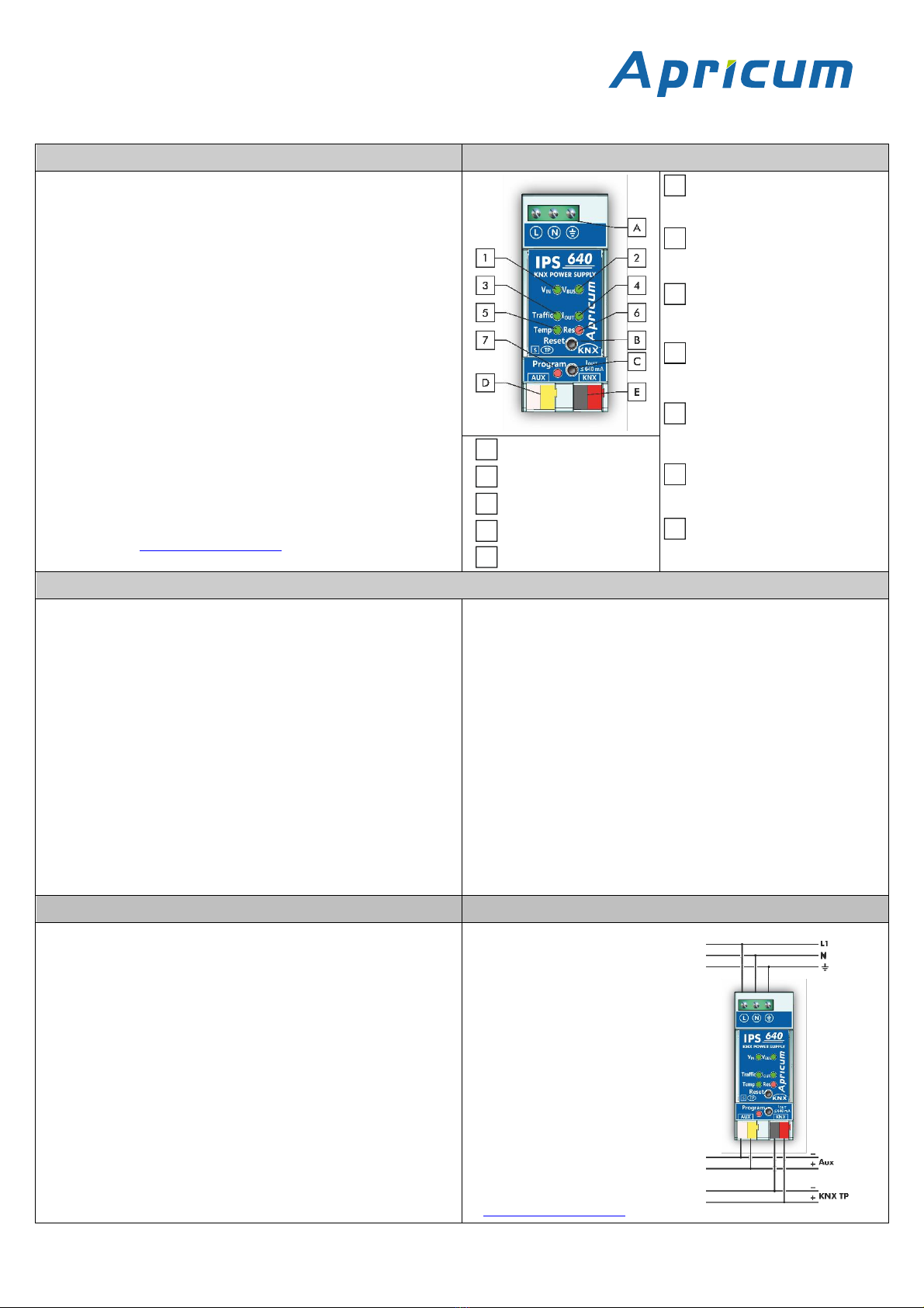
Anschlüsse, Tasten und LEDs
Die IPS640 intelligente KNX Busspannungsversorgung mit erweiterter
Diagnose-und Alarmfunktion versorgt eine Linie des KNX Bussystems mit
einer Spannung von 30V DC. Aufgrund der kompakten Bauweise werden
nur 2 TE auf der Hutschiene benötigt. Die IPS640 verfügt auch über einen
zusätzlichen, unverdrosselten Spannungsausgang. Beide Ausgänge sind
überlastsicher und kurzschlussfest. Betriebszustände von Gerät und KNX
TP Linie sind an der LED-Anzeige ablesbar.
Die KNX TP Linie kann per Objekt und per Resettaste zurücksetzt
werden. Zur Diagnose stehen Messwerte von KNX Busspannung,
Ausgangsstrom, Betriebstemperatur und Betriebszeiten (gesamt/ ab
letztem Startup) zur Verfügung. Per Alarm wird informiert, dass ein
Messwert seinen Normalbereich oder einen vorher festgelegten Bereich
verlassen hat. Insgesamt können bis zu acht verschiedene Alarme
konfiguriert werden.
Die IPS640 kann ihre Info-Telegramme auf Anfrage, regelmäßig und nach
bestimmten Ereignissen verschicken. Details (Anzahl/Dauer) zu
Kurzschluss, Überlast sowie vorher konfigurierten Schwellenwert-
Überschreitungen sind zugänglich. Ebenso wird nach Rückkehr zum
Normalbetrieb, Geräteneustart, KNX Busneustart informiert. Heartbeat-
Telegramme signalisieren einwandfreies Funktionieren.
Die Anforderungen der Direktiven EMC, RoHS und LVD sowie Standards
für Wohn & Gewerbebereiche als auch Industriebereiche werden erfüllt.
Der vollständige Text der EU-Konformitätserklärung ist unter der
folgenden Internetadresse verfügbar: www.apricum.com/ips640
Eingangsspannung VIN
<off>: VIN ist 195…265 V AC
rot: VIN ist außerhalb dieses
Bereichs
Busspannung VBUS
grün: VBUS ist 28…31 V DC
rot: VBUS ist außerhalb dieses
Bereichs
Telegrammverkehr
grün (blinkend):
Telegrammverkehr < 80 %
rot: Telegrammverkehr > 80 %
Ausgangsstrom IOUT
grün: IOUT < 640 mA
orange: IOUT ist 640…900 mA
rot: IOUT > 900 mA (Überlast)
Temperatur
grün: Temperatur ist 0…75 °C
rot: Temperatur ist außerhalb
dieses Bereichs
Netzanschluss
Resettaste
KNX-Bus Reset
rot: Neustart der KNX Linie wird
durchgeführt
Programmiertaste
Hilfsspannungsanschluss
Programmier-LED
rot: Programmier-Modus an
KNX TP Anschluss
Technische Angaben
Versorgung
Netzspannung:
Verlustleistung (offen):
Verlustleistung (normal):
Leistungsbedarf (normal):
Leistungsbedarf (max., Überlast):
Gehäuse
Maße (HxBxT):
Montage (IEC60715):
Breite:
Netzanschluss:
KNX Bus-Anschluss:
AUX-Anschluss:
Gewicht:
Umgebungsbedingungen
Arbeitstemperatur:
Lagertemperatur:
Umgebende Feuchte:
230 V AC ±15 % @ 50 Hz
1,2 W
4,7 W
23 W
42 W
94 x 36 x 71 mm
35 mm-Schiene (DIN, TH35)
2 TE zu je 18 mm
Schraubklemmen 0,3…2,5 mm2
(max. Anzugsdrehm. 0,4 Nm)
KNX-Klemme (rot/schwarz)
KNX-Klemme (weiss/gelb)
185 g
-5…45 °C
-20...70 °C
5…93 % (nicht-kondensierend)
Ausgangsleistung
KNX Busspannung:
AUX Hilfsspannung:
Nennstrom:
Maximalstrom (gesamt):
Überbrückungszeit bei Netzausfall:
Effizienz bei Normallast:
Elektrische Sicherheit
Verschmutzungsgrad (IEC60664):
Schutzart (IEC60529):
Überspannungskategorie(IEC60664):
Freigabe (ISO/IEC14543-3):
CE Kennzeichnung
EU Direktiven:
Standards:
28…31 V DC (SELV)
28…31 V DC (SELV)
640 mA
1,2 A
> 100 ms
82 %
2
IP20
III
KNX-zertifiziert
LVD (2014/35/EU)
EMC (2014/30/EU)
RoHS (2011/65/EU)
EN50581, EN61000-6-2/-3,
EN61558-1/-2-16,
EN IEC 63044-5-1/-2/-3
Montage, Inbetriebnahme und Sicherheit
Installation und Wartung
•Nach dem Anschließen arbeitet das Gerät mit seinen Standard-
einstellungen wie vorgesehen
•Das Gerät darf nur von einer Elektrofachkraft oder autorisiertem
Fachpersonal installiert und in Betrieb genommen werden
•Bei der Planung und Errichtung von elektrischen Anlagen sind die
einschlägigen Richtlinien, Vorschriften und Bestimmungen des
jeweiligen Landes zu beachten
•Zur Montage ein geeignetes Werkzeug nach IEC60715 verwenden
•Installation nur in Verteilerkästen oder geschlossenen Gehäusen
•Installation nur auf geeigneter DIN-Hutschiene (TH35)
•Stromführende Teile müssen vollständig abgedeckt werden
•Der Berührschutz muss durch den Schaltschrank gewährleistet sein
•Die Abdeckung darf nicht ohne Hilfe eines Werkzeuges zu entfernen
sein
•Die KNX-Buslinie, wie für alle üblichen KNX-Anschlüsse, mit
abisoliertem KNX-Buskabel und KNX TP-Klemme anschließen
•Beim Anschließen nicht die elektrischen Isolationen beschädigen
•Installation nur in trockener Umgebung
•Zum Konfigurieren die ETS verwenden
•Die Zugänglichkeit zum Gerät
muss aus Gründen der
Bedienbarkeit und Inspektion
stets gewährleistet sein
•Das Gehäuse darf nicht geöffnet
werden
•Gerät vor Feuchtigkeit, Schmutz
und Beschädigung schützen
•Das Gerät ist wartungsfrei
•Wenn nötig, das Gerät mit
einem trockenen Tuch reinigen
•Bei Beschädigung (bei
Transport, Lagerung) darf keine
Reparatur vorgenommen
werden; Gerät zurückschicken
•Konfiguration-Details und ETS-
Datenbank:
www.apricum.com/ips640
1
2
3
4
5
A
B
6
C
D
7
E
Table of contents
Languages: