Aprimatic ER-REF Owner's manual

- 1 -
43
80
34
Ø 80
Fig.1
Fig.2
Fig.5
Fig.4
Fig.6
Fig.3
DIMENSIONI ER-REF / ER-REF DIMENSIONS /
DIMENSIONS ER-REF / ABMESSUNGEN
ER-REF / DIMENSIONES ER-REF
ER-REF
INSTALLAZIONE / INSTALLATION / MONTAGE /
MONTAGE / INSTALACION
Vite autofilettante / Self-tapping
screw /Vis autotaraudeuse /
Selbstschneidende Schraube /
Tornillo autorroscante
Tassello
Wall plug
Cheville
Dübel
Taco
Guarnizione
Seal / Joint
Dichtung
Junta
Coperchio / Cover /
Couvercle / Deckel / Tapa
Vite di
bloccaggio
coperchio /
Cover fixing
screw /
Base di supporto / Base / Base de
support / Stützplatte / Base de soporte
Scheda
Control card
Carte
Platine
Tarjeta
Vis de fixation couvercle
Deckel-schraube
Tornillo de bloqueo tapa
Datidipreforatura/Drilling
data / Caractéristiques du
préperçage / Bohrbild /
Datos de pre-taladrado
Tassello a
muro /Wall
plug / Cheville
murale /
Wanddübel /
Taco de pared
Ø 5
Lamiera /
Sheet metal /
Tôle / Blech /
Chapa
Ø 2,65 ÷2,85
Per inserire i cavi nella morsettiera liberare
i morsetti premendo con un cacciavite. /
Release the terminals with a screwdriver to
insertthewires./Pourintroduirelescâblesdans
le bornier, dégager les bornes en exerçant
une pression à l’aide d’un tournevis. / Zum
Einführen der Kabel
indieKlemmleiste die
Klemmen mit einem
Schraubendreher
öffnen./Paraintroducir
los cables en la
regleta de bornes
liberar los bornes
ejerciendo presión
con un destornillador. Abbassare
completamente
il coperchio /
Allineare le tacche e premere
dolcemente/Alignthenotches
and press gently / Aligner les
repèresetappuyerdoucement
.Die
Bezugsmarken
abstimmen
und sanft
eindrücken /
Alinear las
muescas y
presionar
levemente
Slide the cover all the way
down/Baissercomplètement
le couvercle / Den Deckel
ganz einschie-ben / Bajar
completamente la tapa
Fotocellula a riflessione polarizzata a uso
residenziale /
Polarised reflection photocell
for residential use /
Cellule photoélectriques
à réflexion polarisée à usage résidentiel
/ Polarisierte Reflexionslichtschranke für
den privaten Wohnbereich / Fotocélula de
reflexión polarizada para uso residencial
Fig.8
Fig.7a Fig.7b
Fig.8a
Fig.8b Fig.8c
Questo prodotto è di libero uso in tutti i Paesi della
Comunità Europea./This product can be used in
the whole European community freely./ Ce produit
peut être utilisé librement dans la communauté
européenne entière./ Dieses produkt kann in der ganzen
Europäischen gemeinschaft frei benutzt werden./ Este
producto puede utilizarse libremente en la Comunidad
Europea entera.
cod. B4786000 rev. ott. 2006

- 2 -
Fig.9
123*45
+
-
TST COM NC/NO
+
-
TST COM NC/NO
L
123*45
R
JP2
JP
JP1
1
2
3
4
5
JP jumper selezione tipo di contatto Relé / select type of relay
contact / sélection type de contact du relais / Auswahl des
Relais-Kontakttyps /selección del tipo de contacto del relé:
=
NC
=
NO
JP1* jumper attivazioneTEST fotocellula /photocell
TEST activation jumper /cavalier servant à activer le
TEST pour photocellule /
Jumper zur Aktivierung des
Lichtschranken-TESTs
/ jumper activaciónTEST fotocélula:
= test abilitato = test disabilitato
test enabled test disabled
test activé test désactivé
test aktiviert test deaktiviert
test habilitado test
deshabilitado
Statodelcontattoconfotocellulaalimentataepassaggiolibero/Switch
status with photocell powered on and passage free / État du contact
avec cellule photoélectrique alimentée et passage libre / Zustand des
KontaktsbeiversorgterLichtschrankeundfreiemDurchgang /Estado
del contacto con fotocélula alimentada y paso libre.
JP2
jumper esclusione LED puntamento /
Alignment LED
enabling jumper /
cavalier désactivation LED pointage /
Jumper Ausschaltung Ausricht-LED
/ jumper exclusión LED
alineación:
= LED abilitato = LED disabilitato
LED enabled LED disabled
LED activée LED désactivée
LED aktiviert LED deaktiviert
LED habilitado LED
deshabilitado
LEGENDA / LEGEND / LÉGENDE / LEGENDE / LEYENDA:
*Abilitareiltest fotocellula (jumper JP1 inseritoemorsetto 3 collegato) solo in abbinamentoadapparecchiature
Aprimatic dotate di tale funzionalità./ *Perform the Photocel test (JP1 jumper fitted andTerminal 3 connected)
using Aprimatic control unit with this function only. / *Activer le test pour photocellule (cavalier JP1 branché
et borne 3 connectée) uniquement en présence de platines Aprimatic dotée de cette fonction. / *Aktivieren Sie
den Lichtschrankentest (bei eingesetztem Jumper JP1 und angeschlossener Klemme 3) nur mit Aprimatic
Steuerungen, die über diese Funktion verfügen./*Habilitareltest fotocélula (jumperJP1 introducido y borne 3
conectado) sólo en combinación con equipos de control Aprimatic provistos de dicha funcionalidad.
!
OPTIONAL / OPTIONALS / EN OPTION /
OPTIONEN / OPCIONAL
ccolonnettadisupporto/support column / colonne
de support / Säule / columna de soporte
dcatadiottro per colonnetta / reflector for support
column / catadioptre pour colonne / Rückstrahler für
Säule / catadióptrico para columna
epiastra a saldare/avvitare / back plate for screw
fixing/welding /plaque à souder/visser /Verschweiß-
/Verschraubplatte / placa para soldar o atornillar
fsupporto e piastra orientabili / angle adjustable
support and back plate / support et plaque
orientables / Verstellbare Halterung und Platte /
soporte y placa orientables
gparaluce per catadiottro circolare / shade for
round reflector / pare-soleil pour catadioptre
circulaire/Lichtschutzblendefür rundenRückstrahler
/ capuchón para catadióptrico circular
L=LED di puntamento / Alignment LED / LED de
pointage / Ausricht-LED / LED de alineación
R=Relé contatto / Switching relay / Relais contact /
Kontaktrelais / Relé contacto

- 3 -
DATI TECNICI
GENERALITÀ
La fotocellula ER-REF è composta da un trasmettitore e un
ricevitore, alloggiati entrambi nello stesso contenitore plastico e
daun catadiottro riflettente.La luce rossa emessa è polarizzata
tramiteappositifiltri,questopermetteallaER-REFdidistinguere
oggetti altamente riflettenti quali specchi o carrozzerie molto
lucide; tali oggetti verranno quindi correttamente rilevati
come ostacoli.
La tenuta dell’acqua è garantita da un’apposita guarnizione
di gomma.
La fotocellula può essere installata in colonnetta (OPTIONAL)
o direttamente in parete (tramite viti e tasselli forniti nella
confezione).
I cavi di collegamento possono essere introdotti sia dal retro
del contenitore sia dalla parte inferiore in modo da agevolare
ogni tipo d’installazione.
a3 -Fissareiltuttoallapareteutilizzandolevitie/oitasselliforniti
nella confezione (fig.4) e un cacciavite adeguato.
a4
- Effettuare i collegamenti alla morsettiera (vedi istruzioni di seguito).
a5- Fissare al muro il catadiottro alla stessa altezza della
fotocellula realizzando il corretto allineamento.
a6 -Al termine prendere il coperchio e incastrarlo al fondo
del contenitore in modo da avere la tacca di riferimento
presente sul lato del coperchio allineata rispetto alla tacca
di riferimento della guarnizione (fig.6); quindi premere il
coperchio contro la base e in seguito farlo slittare verso il
basso sino a far coincidere il foro della vite di chiusura con
la relativa sede filettata sulla base. Infine avvitare la vite di
bloccaggio del coperchio.
ATTENZIONE:Assicurarsi che l’allineamento delle fotocellule sia
sufficiente a garantire il buon funzionamento del gruppo.
Nel caso la struttura del cancello non permetta un allineamento
ottimale è disponibile il supporto fotocellula orientabile
(acquistabile come accessorio OPTIONAL).
ATTENZIONE: Non pulire il coperchio con benzina, alcool o
diluenti in genere, onde preservarne le caratteristiche ottiche;
usare acqua e detergente neutro.
b - Montaggio su colonnetta
b1 -Installare la colonnetta e preparare il collegamento.
b2 -
Aprire la fotocellula e collegarla come descritto nei punti a2, a4.
b3-Montare la guarnizione, indi montare la fotocellula
nell’apposito supporto in plastica. Al termine infilare il tutto
nella colonnetta (fig.7/a) e bloccare la fotocellula dal retro
mediante l’apposita vite.
b4 -Fissareilcatadiottroall'altezzadellafotocellulaecontrollare
l'allineamento.
Seanche ilcatadiottrovieneinstallatosucolonnetta è necessario
acquistare il catadiottro rettangolare (OPTIONAL) fig.7/b.
b5 -Chiudere la fotocellula come descritto al punto a6.
c -Montaggio su piastra a saldare/avvitare
c1 - Montare la piastra, mediante saldatura o con viti, nella
posizione prescelta (fig.8a/b/c).
Per il fissaggio a vite si consiglia di usare quelle fornite nella
confezione delle fotocellule.
ATTENZIONE: Non usare MAI la saldatrice con la fotocellula già
montata sulla piastra.
c2 - Aprire la fotocellula, collegarla e chiuderla e fissare a muro
il catadiottro (punti a2, a4, a5, a6).
c3 -
Montarelaguarnizioneefissarelafotocellulaallapiastramediante
le viti incluse nella confezione della piastra, come da fig.8.
COLLEGAMENTO E ALLINEAMENTO (fig.9)
- Collegare la scheda seguendo lo schema di fig.9.
ATTENZIONE: Usare cavi appropriati e comunque aventi sezione
NON INFERIORE a 0,5 mm.
ATTENZIONE
:Consultaresempreleistruzionidicollegamentodell’ap-
parecchiatura di comando alla quale si collegano le fotocellule!
MANEGGIARE CON CURA! Perevitare di danneggiare il circuito
e/o i componenti e di lasciare impronte sulle lenti,si raccomanda
di far pressione solo sulla morsettiera.
- Controllare il buon allineamento mediante il LED rosso
presentesullafotocellula.Ilpuntamentocorrettoèconfermato
dal LED che si accende con intensità modulare: maggiore
intensità luminosa = migliore allineamento.
Per migliorare l’allineamento è possibile variare leggermente
la posizione del catadiottro.
Al termine dell'allineamento si consiglia di togliere il jumper JP2
perescludereilLED rossodi puntamento e limitarel'assorbimento
della fotocellula.
ISTRUZIONI PER L’INSTALLAZIONE
ATTENZIONE!
Maneggiare con cura per non danneggiare i
componenti!
I
Alimentazione
24 Vdc/Vac
Potenza assorbita max. 3 W
Portata contatto relè ricevitore max 1A a 24Vdc per carichi resistivi
max 0,5A a 24Vdc per carichi non resistivi
Distanza operativa max. 12 m
Tempo di intervento 20 ms
Temperatura di funzionamento -15 ÷ +70˚c
Umidità relativa
< 90% NON CONDENSANTE
Reiezione alla luce 20000 lux
Grado di protezione IP 45
Contenuto della confezione q.tà
Fotocellula rice-trasmittente 1
Catadiottro rotondo Ø 80mm 1
Confezione viti per fissaggio:
- tasselli ad espansione 4
- viti autofilettanti 3,5x25,4 4
- vite autofilettante 2,2x6,5 1
- vite autofilettante 2,9x12,7 1
Foglio istruzioni 1
Fotocellula a riflessione polarizzata ad uso residenziale
ISTRUZIONITECNICHE
a -
Apertura, chiusura e fissaggio a muro
a1 -Togliere la guarnizione in gomma posta sul retro della
fotocellula per utilizzarla come dima per segnare i 3 punti di
fissaggio (fig.2).Effettuare i fori (vedi anche fig.4).
a2 -Aprire il contenitore della fotocellula facendo slittare verso
l’altoilcoperchioserigrafatodicirca1cm,inseguitosollevare
il coperchio ottenendo così l’apertura del contenitore (fig.3).
Rimontare la guarnizione sul retro della base.
ER-REF
Ap
H min
H
RISPETTARE!
altezza minima dal suolo delle
fotocellule:Hmin = 25 cm.
altezza consigliata H = 45/50 cm.
POSIZIONAMENTO
ATTENZIONE: per assicurare il buon funzionamento del
sistema CONTROLLARE IL CORRETTO
ALLINEAMENTO DELLE FOTOCELLULE!

Polarised reflection photocell for residential use
TECHNICAL INSTRUCTIONS
TECHNICAL SPECIFICATIONS
GB
Power supply
24 Vdc/Vac
Absorbed power Max. 3 W
Receiver relay contact output max. 1A at 24Vdc with ohm loads
max. 0.5A at 24Vdc with inductive loads
Operating distance Max. 12 m
Response time 20ms
Operating temperature -15 ÷ +70˚C
Humidity <90% non condensing
Light rejection 20000 lux
Protection rating IP 45
Kit contents Q.ty
Photocell transmitter-receiver 1
Round reflector, Ø 80mm 1
Packet of fixing screws: - wall plugs 4
- self-tapping screws, 3.5x25.4 4
- self-tapping screw, 2.2x6.5 1
- self-tapping screw, 2.x12.7 1
Instruction sheet 1
ER-REF
Ap
H min
H
TO BE RESPECTED!
Minimum height of photocell from
the ground:Hmin = 25 cm.
Recommended height H = 45/50 cm.
POSITIONING
IMPORTANT: MAKE SURETHATTHE PHOTOCELLS
ARE ACCURATELY ALIGNED TO ENSURE
CORRECT SYSTEM FUNCTIONING!
- 4 -
DESCRIPTION
TheER-REFphotocellunitcomprisesatransmitterandreceiver,
installed in the same plastic housing, plus a reflector. The
red light emission is polarised by special filters. This permits
the ER-REF photocell to detect even highly reflective objects
like mirrors and shiny vehicle bodywork, ensuring the correct
identification of obstacles.
The unit is kept fully waterproof by a special rubber seal.
The photocell can be installed on an (optional) support column
or on a wall using the dowels and screws provided.
The connection cables can be inserted through the rear or
the bottom of the photocell housing to facilitate installation
in any position.
INSTALLATION
CAUTION!To handle with care to avoid damage to the components!
a4 -Connect the electrical cables to the terminals (see the
instructions below).
a5 -
Fix the reflector to the wall at the same height as the
photocell and correctly in line with it.
a6 - Now take the cover and engage it at the bottom of the base
so that the notch on the side of the cover aligns with the
notch on the seal (see fig.6). Push the cover on to the base
then slide it down until the screw hole in the cover lines
up with that in the base. Finally, secure the cover in place
with the fixing screw.
IMPORTANT!Make surethatthe photocellandreflector are
aligned well enough to ensure correct functioning.
If the structure of the gate makes it impossible to achieve a
good alignment, an (optional) adjustable base is available.
CAUTION! Do not use petrol, alcohol, or solvents of any type to
clean the photocell cover. Use only water and a neutral detergent
to avoid spoiling its optical characteristics.
b -Column installation
b1 -Install the support column and prepare the electrical
wiring.
b2-Open the photocell and connect it up as instructed in
steps a2, a4 above.
b3 -Fit the backing seal then the photocell in the plastic
support. Then slide the unit into the column (see fig.7/a)
and fix the photocell in place from the rear using the screw
provided.
b4 -Fix the reflector at the same height as the photocell and
align the two components.
If you have to install the reflector on a column, use the (optional)
rectangular reflector instead (see fig.7/b).
b5 -Close the photocell as instructed in step a6.
c -Installation on the screw fixed/welded plate
c1 - Screw or weld the plate in the required position (fig.8a/b/c).
For screw mountings,use the screws provided in the photocell kit.
CAUTION! NEVER weld the plate with the photocell in place.
c2 - Open the photocell and make the necessary electrical
connections, then close the unit.Fix the reflector to the wall
(see steps a2, a4, a5, a6).
c3 - Fit the seal and fix the photocell to the plate using the
screws provided with the plate kit (see fig.8).
CONNECTIONS / ALIGNMENT (Fig.9)
- Connect up the control card as shown in fig.9.
CAUTION! Use wires of an appropriate size, and NO THINNER
than 0.5 mm.
WARNING! Always consult the instructions for the control
equipment you are connecting the photocell to!
TO HANDLE WITH CARE to avoid damage to the internal circuits
and components. Do not press on the surface of the optical
parts, do not make fingerprints on. Use your finger to press the
terminal board home.
- Use the red LED on the photocell to check for correct
alignment. The precision of the alignment is shown by
the intensity of the LED. The brighter the LED, the better
the alignment.
Make small adjustments to the angle of the reflector to achieve
the best possible alignment.
On completion of alignment, remove the jumper JP2 to disable
the alignment red LED and reduce the photocell energy
consumption.
a -Opening, closing and wall installation
a1 -Remove the rubber seal from the rear of the photocell, and
use it as a template to mark 3 drilling points (see fig.2). Drill
the necessary holes (see fig.4).
a2 -Slide the screen-printed cover upwards about 1 cm, then
lift it off to open the photocell housing (see fig.3). Replace
the seal at the rear of the base.
a3-Fix the base to the wall with an appropriate small
screwdriver, using the screws and wall plugs provided in
the kit (see fig.4).

- 5 -
Cellule photoélectriques à réflexion polarisée à usage résidentiel
INSTRUCTIONSTECHNIQUES
F
Alimentation
24 Vdc/Vac
Puissance absorbée maxi 3 W
Charge contact relais récep. max 1A à 24Vdc avec charges ohmiques
max 0,5A à 24Vdc avec charges inductives
Distance opérationnelle maxi 12 m
Temps d'intervention 20ms
Température de fonctionnement
-15 ÷ +70˚C
Humidité relative <90% NON CONDENSÉE
Réaction à la lumière 20 000 lux
Degré de protection IP45
Contenu de l'emballage q.té
Cellule photoélectrique émettrice-réceptrice 1
Catadioptre rond Ø 80 mm 1
Emballage vis de fixation : - chevilles à expansion 4
- vis autotaraudeuses 3,5x25,4 4
- vis autotaraudeuse 2,2x6,5 1
- vis autotaraudeuse 2,9x12,7 1
Notice d'instructions 1
ER-REF
Ap
H min
H
À RESPECTER!
hauteur minimale des cellules
photoélectriques au-dessus du
sol:Hmin = 25 cm.
hauteur conseillée H = 45/50 cm.
EMPLACEMENT
ATTENTION: pour garantir le bon fonctionnement du
système S'ASSURER QUE LES
PHOTOCELLULES SONT BIEN ALIGNÉES !
GÉNÉRALITÉS
LacellulephotoélectriqueER-REFcomprendunémetteuretun
récepteur (tous deux contenus dans le même boîtier plastique)
ainsi qu’un catadioptre réfléchissant. La lumière rouge émise
est polarisée au moyen de filtres spéciaux afin de permettre
à la photocellule ER-REF de distinguer des objets hautement
réfléchissantstelsquelesmiroirsoulescarrosseriestrèspolies;
les objets en question seront donc correctement identifiés
commeétantdesobstacles.L’étanchéitéàl’eauestgarantiepar
un joint en caoutchouc prévu à cet effet. La photocellule peut
s’installer sur une colonne (EN OPTION) ou directement au
mur(à l’aide des vis et des chevillesfournies dans l’emballage).
Il est possible de faire passer les câbles de connexion aussi
bien par l’arrière du boîtier que par le bas de façon à faciliter
tous les types d’installation.
CARACTÉRISTIQUESTECHNIQUES
INSTRUCTIONS DE MONTAGE
ATTENTION!
Traiter avec soins pour eviter de abîmer les composants!
a -Ouverture, fermeture et fixation murale
a1 -
Retirer le joint en caoutchouc situé au dos de la cellule
photoélectrique et l’utiliser comme gabarit pour marquer les 3
points de fixation (fig.2).Percer les trous (voir aussi fig.4).
a2 -Ouvrir le boîtier de la photocellule en faisant glisser le
couvercle sérigraphié d’environ 1 cm vers le haut; soulever
ensuite ce dernier pour ouvrir le boîtier (fig.3). Remettre le
joint au dos de la base.
a3 -Fixer le tout au mur à l’aide d'un tournevis approprié
en utilisand des vis et/ou des chevilles fournies dans
l’emballage (fig.4).
a4 -
Effectuer les connexions sur le bornier (voir instructions ci-après).
a5- Fixer le catadioptre au mur à la même hauteur que la
photocellule;vérifier l’alignement.
a6 -Une fois cette opération terminée, prendre le couvercle et
l’encastrer au fond du boîtier de façon que le repère présent
sur le côté du couvercle soit aligné sur le repère du joint
(fig.6); appuyer alors le couvercle contre la base, puis le
faire glisser vers le bas jusqu’à ce que le trou de la vis de
fermeturecoïncideavecsonlogementfiletésurlabase.Pour
finir, visser la vis servant à fixer le couvercle.
ATTENTION: S’assurer que les photocellules sont suffisamment
alignées afin de garantir le bon fonctionnement du groupe.
Au cas où la structure du portail ne permettrait pas un alignement
optimal, il existe un support orientable pour la photocellule
(disponible comme accessoire OPTIONNEL).
ATTENTION: Ne jamais utiliser d’essence, d’alcool ou de diluants
en général pour nettoyer le couvercle afin d’en préserver les
caractéristiques optiques;utiliser de l’eau avec un détergent neutre.
b -Montage sur colonne
b1 -Installer la colonne et préparer le raccordement.
b2-Ouvrir la photocellule et la relier selon les indications
des points a2, a4.
b3-Appliquer le joint, puis monter la photocellule dans le
support plastique prévu à cet effet. Après quoi, introduire
le tout dans la colonne (fig.7/a) et fixer la photocellule par
l’arrière à l’aide de la vis prévue à cet effet.
b4-Fixer le catadioptre à la même hauteur que la
photocellule; contrôler l’alignement.
Si le catadioptre est lui aussi installé sur la colonne, il faut se
procurer le catadioptre rectangulaire (EN OPTION) fig.7/b
.
b5 -Fermer la photocellule en suivant les indications du
point a6.
c -Montage sur plaque à souder/visser
c1 - Monter la plaque par soudage ou à l’aide de vis dans la
position choisie (fig.8a/b/c).
Pour la fixation par vis, il est recommandé d’utiliser les vis
fournies dans l’emballage des photocellules.
ATTENTION: Ne JAMAIS utiliser de soudeuse lorsque la cellule
photoélectrique est déjà montée sur la plaque.
c2 - Ouvrir, connecter et refermer la photocellule; fixer le
catadioptre au mur (points a2, a4, a5, a6).
c3 - Monterlejointet fixerlaphotocelluleàlaplaque àl’aidedes
vis fournies dans l’emballage de la plaque, (voir fig.8).
INSTRUCTIONS DE BRANCHEMENT/ALIGNEMENT (Fig.9)
- Relier la carte selon le schéma de la fig.9.
ATTENTION: Utiliser des câbles appropriés dont la section NE
DOIS PAS ÊTRE INFÉRIEURE à 0,5 mm.
ATTENTION:Toujours consulter les instructions de branchement
de la platine de commande à laquelle les photocellules sont
reliées !
TRAITER AVEC SOINS! Pour NE PAS abîmer le circuit
et/ou les composants et pour éviter des empreintes sur les
parties optiques. Il est recommandé d’appuyer seulement
sur le bornier.
- Contrôler l’alignement à l’aide de la LED rouge présente sur
la photocellule.Le pointage correct est confirmé par la LED
dontl’intensitélumineuse indique laqualitédepointage:plus
la lumière est intense, meilleur est l’alignement.
Il est possible de modifier légèrement la position du catadioptre
pour améliorer l’alignement.
Une fois l’alignement effectué, il est recommandé d’enlever le
cavalier JP2 pour désactiver la LED rouge de pointage et limiter
l’absorption de la photocellule.

- 6 -
Polarisierte Reflexionslichtschranke für den privatenWohnbereich
TECHNISCHE ANLEITUNG
TECHNISCHE DATEN
D
Versorgung 24 Vdc/Vac
Max. Leistungsaufnahme Max. 3 W
Stromfest. Empfängerrelais ohmsche Last Max. 1A bei 24Vdc
induktive Last Max. 0,5A bei 24Vdc
Reichweite Max. 12 m
Ansprechzeit 20ms
Betriebstemperatur -15 ÷ +70˚c
Relative Feuchtigkeit <90% OHNE KONDENSBILDUNG
Lichtfestigkeit 20000 lux
Schutzart IP 45
Packungsinhalt St.
Sender-/Empfängerlichtschranke 1
Runder Rückstrahler Ø 80mm 1
Befestigungsschrauben: Spreizdübel 4
selbstschneidende Schrauben 3,5x25,4 4
selbstschneidende Schraube 2,2x6,5 1
selbstschneidende Schraube 2,9x12,7 1
Bedienungsanleitung 1
ER-REF
Ap
H min
H
EINHALTEN!
Mindesthöhe der Lichtschranke
vom Boden:Hmin = 25 cm.
Empfohlene Höhe H = 45/50 cm.
POSITIONIEREN
ACHTUNG: DIE AUSRICHTUNG DER
LICHTSCHRANKE PRÜFEN, um die einwandfreie
funktion des systems sicherzustellen!
ALLGEMEINES
DieLichtschrankeER-REFbestehtauseinemSenderundeinem
Empfänger, die im selben Plastikgehäuse untergebracht sind,
und aus einem reflektierenden Rückstrahler. Das abgestrahlte
rote Licht wird durch entsprechende Filter polarisiert; auf
diese Weise ist die ER-REF in der Lage, hochreflektierende
Gegenstände, wie beispielsweise Spiegel oder glänzende
Karosserienzuunterscheiden;dieseGegenständewerdendaher
korrektalsHindernisse erkannt.Schutz gegenWasserbietetdie
spezielle Gummidichtung.Der Einbau der Lichtschranke erfolgt
wahlweise in einer Säule (OPTION) oder direkt an der Wand
(Schrauben und Dübel beigepackt).Für eine flexible Installation
lassen sich die Anschlusskabel von der Rück- bzw. Unterseite
des Gehäuses einführen.
MONTAGEANLEITUNG
ACHTUNG!
Sorgfältig handhaben, um die Komponenten nicht
zu beschädigen!
a -Öffnen, Schließen und Wandmontage
a1 -
DierückseitigenGummidichtungderLichtschrankeabnehmen
und als Bohrschablone der drei Fixierstellen verwenden
(Abb.2).Die Fixierbohrungen herstellen (siehe auch Abb.4).
a2 -Den Deckel mit Siebdruckdekor um ca. 1 cm aufschieben
und ihn anschließend ganz aufklappen, wodurch das
Gehäuse der Lichtschranken geöffnet wird (Abb.3). Die
Dichtung wieder rückseitig an der Stützplatte anbringen.
a3-Die Einheit anhand der beigepackten Schrauben bzw.
Dübel und eines passenden Schraubendrehers an der
Wand befestigen (Abb.4).
a4-Den Klemmanschluss ausführen (siehe nachstehende
Anweisungen).
a5- Den Rückstrahler auf derselben Höhe der Lichtschranke
an der Wand befestigen und ausrichten.
a6 -Dann den Deckel am Gehäuseboden einstecken, wobei
die Bezugsmarke an Deckelseite mit der entsprechenden
Marke der Dichtung übereinstimmen muss (Abb.6); den
DeckelgegendieStützplatte drücken und soweitnachunten
schieben, bis Bohrung und Gewindesitz zusammenfallen.
Die Deckelschraube festziehen.
ACHTUNG: Die Ausrichtung der Lichtschranken muss einen
ordnungsgemäßen Betrieb der Anlage gewährleisten.
Sollte wegen derTorstruktur keine optimale Ausrichtung möglich
sein, ist eine verstellbare Lichtschrankenhalterung lieferbar
(als OPTION erhältlich).
ACHTUNG: Der Deckel wird durch Reinigung mit Benzin, Alkohol
bzw. Lösungsmitteln beschädigt. Ausschließlich Wasser und
neutrale Reinigungsmittel verwenden.
b -Befestigung an Säule
b1 -Die Säule anschlussfertig aufstellen.
b2 -Die Lichtschrankeöffnen und wie unter a2, a4 beschrieben
anschließen.
b3-Die Dichtung anbringen und die Lichtschranke an der
Plastikhalterung befestigen. Die Einheit auf die Säule
aufstecken (Abb.7/a) und auf der Rückseite mit der
entsprechenden Schraube sichern.
b4 -DenRückstrahleraufderHöhederLichtschrankebefestigen
und die Ausrichtung prüfen.
Wird der Rückstrahler ebenfalls an einer Säule befestigt, muss
der rechteckige Rückstrahler verwendet werden (als OPTION
erhältlich) Abb.7/b.
b5 -Die Lichtschranke schließen (siehe Punkt a6).
c -Befestigung aufVerschweiß-/Verschraubplatte
c1-Die Platte an der gewünschten Stelle (Abb.8a/b/c)
verschweißen bzw.verschrauben.
ZurVerschraubungsollten diebeigepacktenSchraubenverwendet
werden.
ACHTUNG: Keine Schweißarbeiten bei bereits an der Platte
befestigter Lichtschranke ausführen.
c2 - Die Lichtschranke öffnen, verbinden, schließen und den
Rückstrahler an der Wand befestigen
(siehe a2, a4, a5, a6).
c3 - Die Dichtung anbringen und die Lichtschranke mit den
beigepackten Schrauben an der Platte befestigen, wie in
Abb.8 gezeigt.
HINWEISE ZUM ANSCHLIESSEN/AUSRICHTEN (Abb.9)
- Die Platine gemäß Plan in Abb.9 anschließen.
ACHTUNG: Geeignete bzw. nur Kabel mit einem
MINDESTQUERSCHNITT von 0,5 mm verwenden.
ACHTUNG: Immer unter den Anschlusshinweisen der Steuerung
nachsehen, an die die Lichtschranke angeschlossen wird!
SORGFÄLTIG HANDHABEN!
Keinen Druck auf die optischen Teile
ausüben,umdieSchaltungund/oderKomponentennichtzubeschädigen
und keine Abdrücke zu hinterlassen (nur auf die Klemmleiste drücken).
- Die einwandfreie Ausrichtung anhand der rot LED auf der
Lichtschrankeüberprüfen.DiekorrekteAusrichtungistander
Lichtstärke der LED zu erkennen: je größer die Leuchtkraft
desto besser die Ausrichtung.
ZurVerbesserung der Ausrichtung kann der Rückstrahler leicht
verschoben werden.
Ist die Ausrichtung in Ordnung, sollte der Jumper JP2 entfernt
werden, um die rot Ausricht-LED auszuschalten und so die
Stromaufnahme zu verringern.

- 7 -
Fotocélula de reflexión polarizada para uso residencial
ISTRUCCIONESTÉCNICAS
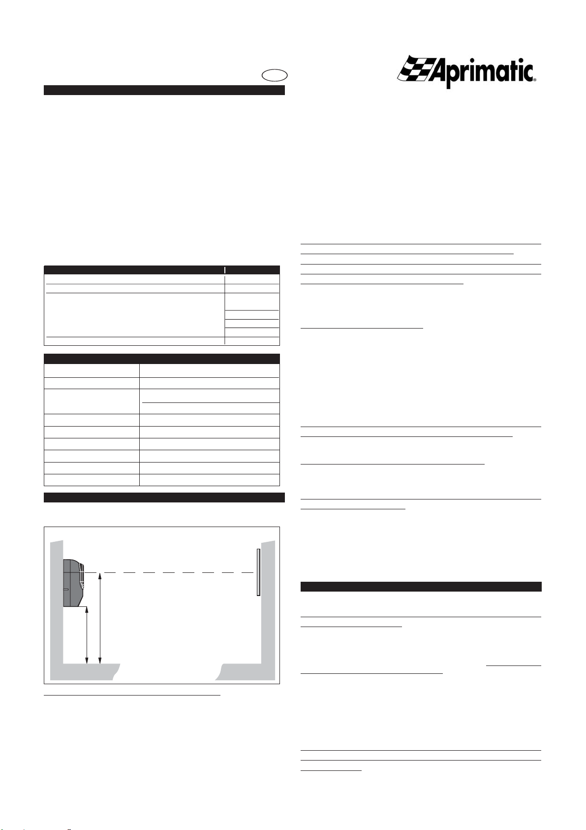
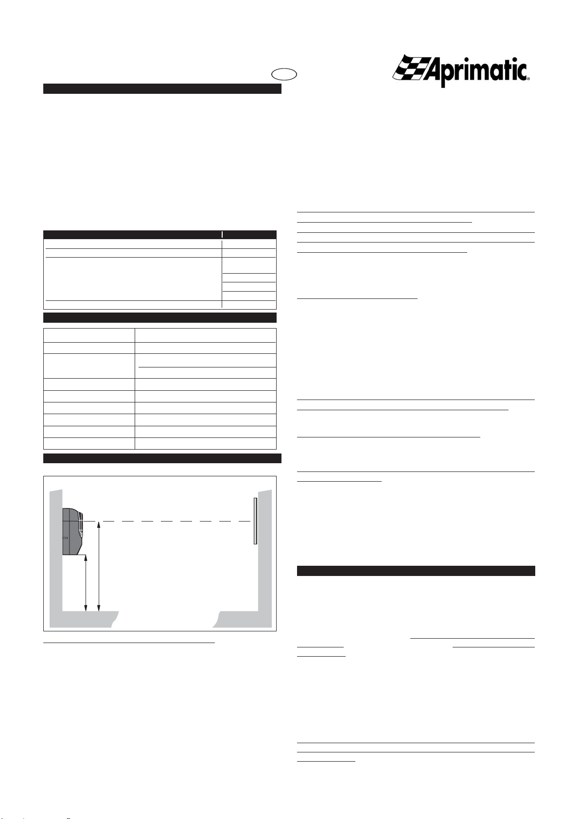
DATOSTECNICOS
E
Alimentación
24 Vdc/Vac
Potencia máx. Consumida máx. 3 W
Capac. contacto relè receptor max 1A a 24Vdc con cargas óhmicas
max 0,5A a 24Vdc con cargas inductivas
Distancia de detección máx. 12 m
Tiempo de intervención 20 ms
Temperatura di funcionam. -15 ÷ +70˚C
Humedad relativa <90% NO CONDENSANTE
Barrera contra la luz 20000 lux
Grado de protección IP 45
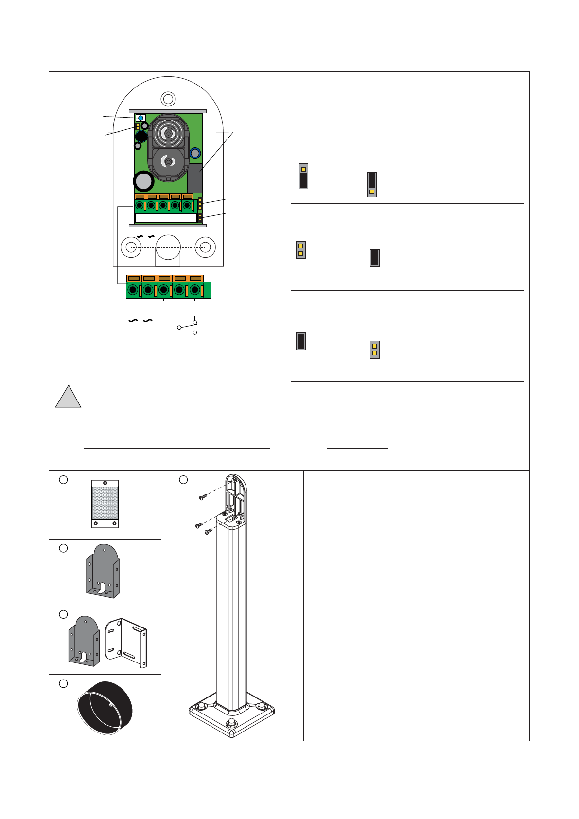
Contenido del paquete ctd.
Fotocélula receptora y transmisora 1
Catadióptrico redondo Ø 80 mm 1
Paquete de tornillos para la fijación:
tornillos de expansión 4
tornillos autorroscantes 3,5x25,4 4
tornillo autorroscante 2,2x6,5 1
tornillo autorroscante 2,9x12,7 1
Hoja de instrucciones 1
ER-REF
Ap
H min
H
¡RESPETAR!
altura mínima desde el suelo
de las fotocélulas:Hmin = 25 cm.
altura aconsejada H = 45/50 cm.
COLOCACIÓN
¡ATENCIÓN: para garantizar el buen funcionamiento del
sistema COMPROBAR QUE LAS FOTOCÉLULAS
ESTÉN CORRECTAMENTE ALINEADAS!
GENERALIDADES
La fotocélula ER-REF está compuesta por un transmisor y un
receptor, ambos alojados en el mismo contenedor plástico y
por un catadióptrico reflectante.
La luz roja emitida está polarizada por medio de filtros, esto
permite a la fotocélula ER-REF distinguir objetos altamente
reflectantes como espejos o carrocerías muy brillantes; por
lo que dichos objetos serán correctamente detectados como
obstáculos.La estanqueidad al agua está garantizada por una
junta de goma. La fotocélula puede fijarse en una columna
(OPCIONAL) o directamente en la pared (mediante los
tornillos y tacos suministrados en dotación). Los cables de
conexión pueden introducirse desde la parte trasera del
contenedor o desde la parte inferior, a fin de facilitar todo
tipo de instalación.
INSTRUCCIONES PARA LA INSTALACIÓN
ATENCIÓN! Manejar con cuidado para NO dañar los componentes!
a -Apertura, cierre y fijación en la pared
a1 -Retirar la junta de goma situada en la parte trasera de
la fotocélula y utilizarla como plantilla para trazar los 3
puntos de fijación (fig.2). Realizar los taladrados (ver
también la fig.4).
a2 -Abrir el contenedor de la fotocélula deslizando 1 cm
aproximadamente hacia arriba la tapa serigrafiada, a
continuación levantar la tapa abriendo de este modo el
contenedor (fig.3). Montar de nuevo la junta en la parte
trasera de la base.
a3-Fijar el conjunto a la pared con un destornillador
apropiado, utilizando los tornillos y/o los tacos
suministrados en dotación (fig.4).
a4-Efectuar las conexiones a la regleta de bornes (ver las
instrucciones que se facilitan a continuación).
a5- Fijarelcatadióptrico en la pared a la misma altura que la
fotocélula, asegurándose de la correcta alineación.
a6-Por último encastrar la tapa en el fondo del contenedor,
de modo que la muesca de referencia que se encuentra
en el lado de la tapa quede alineada con la muesca de
referencia de la junta (fig.6); a continuación apretar
la tapa contra la base y deslizarla hacia abajo hasta
que el taladrado para el tornillo de cierre coincida con
el correspondiente asiento roscado en la base. Para
finalizar, apretar el tornillo de bloqueo de la tapa.
Asegurarse de que la alineación de las fotocélulas sea adecuada
para garantizar el buen funcionamiento del grupo.
En caso de que la estructura de la verja no permita una buena
alineación,está disponible un soporte orientable para la fotocélula
(puede adquirirse como accesorio OPCIONAL).
ATENCIÓN:Nolimpiarlatapa con gasolina,alcoholo disolventes
en general, a fin de preservar sus características ópticas; usar
agua y detergente neutro.
b - Montaje en columna
b1 -Instalar la columna y preparar la conexión.
b2 -Abrir la fotocélula y conectarla como se describe en los
puntos a2, a4.
b3 -Montarlajuntaya continuaciónla fotocélulaenel corres-
pondiente soporte de plástico. Seguidamente introducir
elconjuntoenla columna (fig.7/a) y bloquearlafotocélula
por la parte trasera mediante el respectivo tornillo.
b4 -Fijar el catadióptrico a la altura de la fotocélula y
comprobar que estén correctamente alineados.
Si el catadióptrico también se instala en columna, es preciso
comprar el catadióptrico rectangular (OPCIONAL) fig.7/b.
b5-Cerrar la fotocélula como se describe en el punto a6.
c -Montaje en placa para soltar o atornillar
c1-Montar la placa, mediante soldadura o con tornillos, en
la posición elegida (fig.8a/b/c).
Para la fijación contornillosseaconseja utilizar los suministrados
junto con la fotocélula.
ATENCIÓN: No usar NUNCA el soldador con la fotocélula ya
montada en la placa.
c2 - Abrir la fotocélula, conectarla ycerrarla;por último fijaren
la pared el catadióptrico (ver puntos a2, a4, a5 y a6).
c3-Montar la junta y fijar la fotocélula en la placa mediante
los tornillos suministrados en dotación, tal y como se
indica en la fig.8.
INSTRUCCIONES PARA LA CONEXIÓN/ALINEACIÓN (Fig.9)
- Conectar la tarjeta siguiendo el esquema de la fig.9.
ATENCIÓN:Usar cables apropiados y de sección NO INFERIOR
a 0,5 mm.
ATENCIÓN:Consultar siempre las instrucciones de conexión del
equipo de mando al cual se conectan las fotocélulas!
MANEJAR CON CUIDADO! Para NO dañar el circuito ni/o los
componentes y para evitar huellas digitales NO presionar sobre las
partes ópticas (se aconseja presionar solamente sobre la regleta de
bornes).
- Comprobar la correcta alineación mediante el LED rojo
presente en la fotocélula. Si la alineación es la correcta, el
LED se enciende con intensidad modular:mayor intensidad
luminosa = mejor alineación.
Para mejorar la alineación se puede cambiar ligeramente
la posición del catadióptrico.
Una vez finalizada la alineación se aconseja quitar el jumper
JP2 para excluir el LED rojo de alineación y limitar la absorción
de la fotocélula.

DICHIARAZIONE DI CONFORMITÁ
DECLARATION OF COMPLIANCE
Con la presente Aprimatic S.p.A dichiara sotto la propria responsabilità, che il prodotto ER-REF
- Fotocellula a riflessione polarizzata REFLEX 24 Vdc soddisfa per progettazione e costruzione i
requisiti della Direttiva CEE:
89/336/CEE, articoli 4, 10.1 e 10.2 ed Allegati I e III
Hereby, Aprimatic S.p.A., declares under on our sole responsibility that the product ER-REF - Polarised reflection
photocell REFLEX 24 Vdc meets the design and construction requirements of the EC Directive:
89/336/EC art. 4, 10.1 and 10.2, Annex I and III
La conformità è stata verificata con l’ausilio delle seguenti norme:
Conformity has been checked using the aid of the following standards:
EN 61000-6-3 (2001)
EN 61000-6-2 (2001)
Costruttore: APRIMATIC S.p.A.
Manufacturer: via Leonardo da Vinci, 414 - Z.I. Fossatone -
40060 Villa Fontana di Medicina - BO - ITALY
LEGAL REPRESENTATIVE
Alessandro Minelli
Aprimatic S.p.A.
Via L. Da Vinci, 414
40060 Villa Fontana di Medicina - Bologna - Italy
Tel. +39 051 6960711
Fax +39 051 6960722
info@aprimatic.com - www.aprimatic.com
Table of contents
Other Aprimatic Accessories manuals
Popular Accessories manuals by other brands

Omron
Omron F3W-D052C Series instruction sheet

ECO Sensors
ECO Sensors A-21ZX Instructions for use

Waterpik
Waterpik 200 Series instruction manual

InfinityLab
InfinityLab INSTANTGO 5000 quick start guide

American Standard
American Standard Culinair 7412.100.340 Specification sheet

Sensormate
Sensormate GE1029-DU1D operating manual