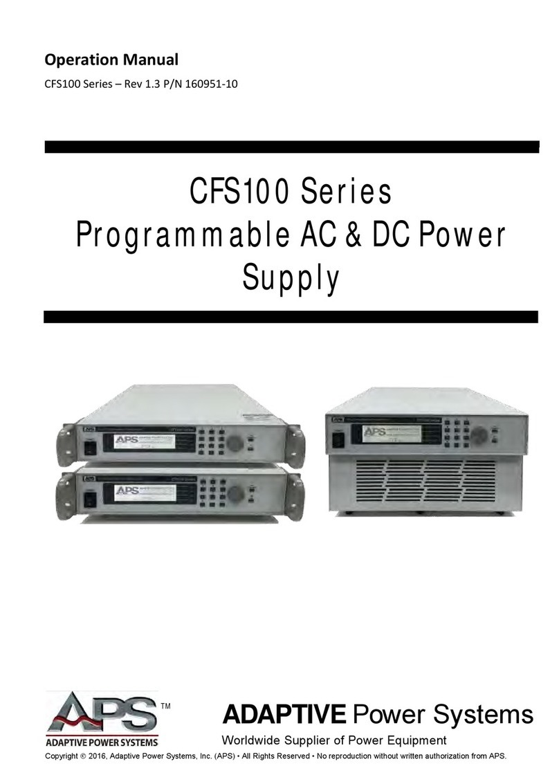
APS CFS300 Series User manual

Operation Manual
CFS300 Series – Rev 1.12 P/N 160952-10
CFS300Series
ProgrammableAC&DCPower
Supply
–
ADAPTIVE Power Systems
Worldwide Supplier of Power Equipment
TM
Copyright 2016, Adaptive Power Systems, Inc. (APS) • All Rights Reserved • No reproduction without written authorization from APS.

CFS300 SERIES OPERATION MANUAL
CONTENTS
Entire Contents Copyright 2016 by Adaptive Power Systems, Inc. (APS) • All Rights Reserved • No reproduction without written authorization from APS.
APS CFS300 Series Power Source Operation Manual Page 2 of 156
PAGE LEFT INTENTIONALLY LEFT BLANK FOR HARDCOPY VERSIONS OF THIS DOCUMENT

CFS300 SERIES OPERATION MANUAL
CONTENTS
Entire Contents Copyright 2016 by Adaptive Power Systems, Inc. (APS) • All Rights Reserved • No reproduction without written authorization from APS.
APS CFS300 Series Power Source Operation Manual Page 3 of 156
Table of Contents
1Contact Information ...................................................................................................................9
2Front Matter.............................................................................................................................10
2.1 Limited Warranty .................................................................................................................................. 10
2.2 Service and Spare Parts Limited Warranty .......................................................................................... 10
2.3 Safety Information................................................................................................................................. 10
2.4 Safety Notices ........................................................................................................................................ 12
3Product Overview.....................................................................................................................14
3.1 General Description............................................................................................................................... 14
3.1.1 Model CFS330................................................................................................................................................... 14
3.1.2 Model CFS360................................................................................................................................................... 14
3.2 Product Features ................................................................................................................................... 14
3.3 Operating Modes .................................................................................................................................. 16
3.4 Voltage Programming ........................................................................................................................... 17
3.4.1 Minimum Voltage............................................................................................................................................. 17
3.4.2 Voltage Range AUTO mode ............................................................................................................................. 17
3.5 Current Protection Modes.................................................................................................................... 18
3.6 Voltage & Current Output Profiles ....................................................................................................... 19
3.6.1 CFS330 AC Mode, Single Phase Output VI Curve............................................................................................ 20
3.6.2 CFS330 AC Mode, Three Phase Output VI Curve............................................................................................ 21
3.6.3 CFS330 DC Mode VI Curve ............................................................................................................................... 22
3.6.4 CFS360 AC Mode, Single Phase Output VI Curve............................................................................................ 23
3.6.5 CFS360 AC Mode, Three Phase Output VI Curve............................................................................................ 24
3.6.6 CFS360 DC Mode VI Curve ............................................................................................................................... 25
4Technical Specifications............................................................................................................26
4.1 AC Output .............................................................................................................................................. 26
4.2 DC Output .............................................................................................................................................. 27
4.3 Metering – AC Mode – Single Phase Mode ......................................................................................... 28
4.4 Metering – AC Mode – Three & Two Phase Mode ............................................................................. 29
4.5 Metering – DC Mode............................................................................................................................. 30
4.6 Protection Modes.................................................................................................................................. 30
4.7 AC Input ................................................................................................................................................. 31
4.7.1 AC Input Power vs AC Output Power – Model CFS330 .................................................................................. 32
4.7.2 AC Input Power vs AC Output Power – Model CFS360 .................................................................................. 32
4.8 System Parameters ............................................................................................................................... 33
4.9 Test Mode Parameters.......................................................................................................................... 33
4.10 Interface and I/O ................................................................................................................................... 34
4.11 Dimensions & Weight ........................................................................................................................... 34
4.12 Environmental ....................................................................................................................................... 34
4.13 Safety & Regulatory............................................................................................................................... 35
5Unpacking and Installation .......................................................................................................36
5.1 Inspection .............................................................................................................................................. 36
5.2 Proper Lifting and Handling Guidelines................................................................................................ 36
5.3 Unpacking .............................................................................................................................................. 37
5.4 Ship Kits.................................................................................................................................................. 39
5.4.1 CFS330 Ship Kit Contents ................................................................................................................................. 39
5.4.2 CFS360 Ship Kit Contents ................................................................................................................................. 40
5.5 AC Input Connections............................................................................................................................ 41
5.6 Grounding Requirements ..................................................................................................................... 41

CFS300 SERIES OPERATION MANUAL
CONTENTS
Entire Contents Copyright 2016 by Adaptive Power Systems, Inc. (APS) • All Rights Reserved • No reproduction without written authorization from APS.
APS CFS300 Series Power Source Operation Manual Page 4 of 156
5.7 Check Line Voltage ................................................................................................................................ 42
5.8 AC Input Connection ............................................................................................................................. 42
5.8.1 CFS330 AC Input Connections.......................................................................................................................... 43
5.8.2 CFS360 AC Input Connections.......................................................................................................................... 44
5.8.3 Available CFS360 AC Input Configurations...................................................................................................... 45
5.8.4 AC Input Shorting Bars for CFS360................................................................................................................... 45
5.8.5 Recommend AC Input Wire Gauges................................................................................................................ 46
5.9 Cleaning.................................................................................................................................................. 46
5.10 Powering Up .......................................................................................................................................... 47
5.11 In Case of Malfunction .......................................................................................................................... 47
5.12 Output Terminals .................................................................................................................................. 48
5.12.1 Output Terminal Location ................................................................................................................................ 48
5.12.2 Output Load Connection Configurations ........................................................................................................ 49
5.12.3 Recommended Output Wire Size.................................................................................................................... 49
5.12.4 Voltage Sense Modes ....................................................................................................................................... 50
5.12.5 Connecting a UUT............................................................................................................................................. 51
5.13 Rear Panel Controls and Connectors.................................................................................................... 52
5.14 Remote Output Interface...................................................................................................................... 53
5.15 Remote Input and Remote Interlock Interface.................................................................................... 53
5.15.1 Remote Memory Selection .............................................................................................................................. 54
5.15.2 Remote Output Interlock ................................................................................................................................. 54
5.16 Remote Control Programming Interfaces............................................................................................ 55
5.16.1 RS232 Serial Interface....................................................................................................................................... 55
5.16.2 USB Interface .................................................................................................................................................... 56
5.16.3 LAN Interface (Option) ..................................................................................................................................... 56
5.16.4 GPIB Interface (Special Order) ......................................................................................................................... 57
5.16.5 Control Commands........................................................................................................................................... 58
5.16.6 Sending Commands over RS232 / USB or LAN ............................................................................................... 58
5.16.7 Receiving Commands over RS232 / USB or LAN............................................................................................. 58
6Front Panel Operation ..............................................................................................................59
6.1 Powering On .......................................................................................................................................... 59
6.2 Front Panel Layout ................................................................................................................................ 61
6.3 LED Status Indications ........................................................................................................................... 62
6.4 Shuttle Knob .......................................................................................................................................... 62
6.5 Setup Screen Readouts......................................................................................................................... 63
6.6 Main Menu Soft Keys............................................................................................................................ 64
6.7 Lower Level Menu Soft Keys................................................................................................................. 65
6.8 Password Protection ............................................................................................................................. 66
6.8.1 Password Assignment or Change .................................................................................................................... 66
6.8.2 Forgotten Password ......................................................................................................................................... 66
6.9 Operating Mode – Selecting ................................................................................................................. 67
6.9.1 Available Operating Modes.............................................................................................................................. 67
6.9.2 On Screen Operating Mode Indication............................................................................................................ 67
6.10 PROGRAM Mode Operation................................................................................................................. 69
6.10.1 PROGRAM Mode System Settings................................................................................................................... 69
6.10.2 Auto Run Mode Selections............................................................................................................................... 70
6.10.3 Out Mode.......................................................................................................................................................... 70
6.10.4 Single Step Modes ............................................................................................................................................ 71
6.10.5 Alarm Settings................................................................................................................................................... 71
6.10.6 LCD Contrast ..................................................................................................................................................... 72
6.10.7 Power-Up Settings............................................................................................................................................ 72
6.10.8 Loop Cycle Settings........................................................................................................................................... 73
6.10.9 Results Display Mode Settings ......................................................................................................................... 73

CFS300 SERIES OPERATION MANUAL
CONTENTS
Entire Contents Copyright 2016 by Adaptive Power Systems, Inc. (APS) • All Rights Reserved • No reproduction without written authorization from APS.
APS CFS300 Series Power Source Operation Manual Page 5 of 156
6.10.10 Over Current Fold Mode Settings .................................................................................................................... 74
6.10.11 Keyboard Lock Mode Settings ......................................................................................................................... 74
6.10.12 Memory Lock Mode Settings........................................................................................................................... 75
6.10.13 Voltage Sense Mode Settings .......................................................................................................................... 77
6.10.14 External Trigger Out Settings ........................................................................................................................... 77
6.10.15 Function Settings (Output Phase Mode) ......................................................................................................... 78
6.11 PROGRAM MODE - Using Memories and Steps.................................................................................. 79
6.11.1 Selecting a Memory Location .......................................................................................................................... 79
6.11.2 Assigning a Name to a Memory Location ....................................................................................................... 80
6.11.3 Selecting a Program Step ................................................................................................................................. 81
6.11.4 Program Step Parameters Available................................................................................................................ 82
6.11.5 Editing Step Parameters................................................................................................................................... 85
6.12 PROGRAM Mode - Step Parameter Details ......................................................................................... 86
6.12.1 Phase Angles ..................................................................................................................................................... 86
6.12.2 Memory Cycles ................................................................................................................................................. 87
6.12.3 Voltage Programming ...................................................................................................................................... 87
6.12.4 Frequency Programming.................................................................................................................................. 88
6.12.5 Measurement Limits Programming ................................................................................................................ 89
6.12.6 Time Duration Programming ........................................................................................................................... 90
6.12.7 Transient Programming.................................................................................................................................... 91
6.12.8User Prompt Programming.............................................................................................................................. 94
6.12.9 Step Cycle Programming .................................................................................................................................. 95
6.12.10 Connect Mode Programming .......................................................................................................................... 95
6.12.11 Reviewing Test Results ..................................................................................................................................... 96
6.13 PROGRAM Mode Execution ................................................................................................................. 97
6.13.1 Initiating a Test.................................................................................................................................................. 97
6.13.2 Monitoring Test Execution............................................................................................................................... 97
6.13.3 Cycle Display Mode .......................................................................................................................................... 98
6.13.4 Operator Interruption and Voltage Adjust...................................................................................................... 98
6.13.5 Triggering a Voltage Transient ......................................................................................................................... 99
6.13.6 End of Test Status ........................................................................................................................................... 100
6.14 MANUAL AC Mode Operation............................................................................................................ 101
6.14.1 Available Parameters in MANUAL Mode ...................................................................................................... 101
6.14.2 Programming MANUAL mode parameters .................................................................................................. 101
6.15 MANUAL AC Mode Execution ............................................................................................................ 102
6.16 MANUAL DC Mode Operation............................................................................................................ 104
6.16.1 Available Parameters in DC Mode................................................................................................................. 104
6.16.2 Programming DC mode parameters ............................................................................................................. 104
6.17 MANUAL DC Mode Execution ............................................................................................................ 105
7Remote Control Programming................................................................................................106
7.1 Overview .............................................................................................................................................. 106
7.2 Command Syntax ................................................................................................................................ 106
7.2.1 Command Terminators.................................................................................................................................. 106
7.2.2 Numeric Parameters ...................................................................................................................................... 106
7.2.3 Parameter Unit Options .................................................................................................................................106
7.2.4 Command Delay Recommendation .............................................................................................................. 106
7.3 Syntax Notation Convention............................................................................................................... 107
7.4 Test Control Command and Query Syntax ........................................................................................ 108
7.5 Split Phase Mode Commands............................................................................................................. 111
7.6 Three Phase Mode Commands .......................................................................................................... 113
7.6.1 Voltage Measurement Commands – 3 Phase .............................................................................................. 113
7.6.2 Measurement Commands – 3 Phase ............................................................................................................ 114
7.7 Parameter Setup Command and Query Syntax ................................................................................ 115

CFS300 SERIES OPERATION MANUAL
CONTENTS
Entire Contents Copyright 2016 by Adaptive Power Systems, Inc. (APS) • All Rights Reserved • No reproduction without written authorization from APS.
APS CFS300 Series Power Source Operation Manual Page 6 of 156
7.8 System Command and Query Syntax................................................................................................. 117
7.9 IEEE488.2 Common Commands......................................................................................................... 118
7.9.1 Command Commands Summary Table ........................................................................................................ 118
7.9.2 *IDN?............................................................................................................................................................... 119
7.9.3 *RST.................................................................................................................................................................119
7.9.4 *TST? ............................................................................................................................................................... 119
7.9.5 *CLS .................................................................................................................................................................119
7.9.6 *OPC / *OPC? ................................................................................................................................................. 119
7.9.7 *WAI................................................................................................................................................................ 119
7.9.8 *ESR? ............................................................................................................................................................... 120
7.9.9 *ESE <value> / *ESE?...................................................................................................................................... 120
7.9.10 *STB? ............................................................................................................................................................... 120
7.9.11 *SRE <value> / *SRE? ..................................................................................................................................... 120
7.9.12 *PSC {1|0} / *PSC?.......................................................................................................................................... 120
8USB Driver Installation............................................................................................................121
8.1 Overview .............................................................................................................................................. 121
8.2 USB Driver Installation ........................................................................................................................ 121
9LAN Interface Configuration ...................................................................................................126
9.1 Overview .............................................................................................................................................. 126
9.2 Collect Network Information.............................................................................................................. 126
9.3 Saving LAN Settings ............................................................................................................................. 126
9.4 LAN Option Setup Menu..................................................................................................................... 128
9.4.1 IP Setup Mode ................................................................................................................................................ 128
9.4.2 Manual IP Address Setting ............................................................................................................................. 129
9.4.3 Gateway Address Setting ............................................................................................................................... 129
9.4.4 Subnet Mask Setting....................................................................................................................................... 130
9.4.5 Device Name Setting ...................................................................................................................................... 130
9.4.6 MAC Address .................................................................................................................................................. 131
9.5 Establishing LAN connection using NI MAX Explorer ........................................................................ 132
9.6 LAN Interface Specific Commands and Queries ................................................................................ 141
9.6.1 Communication Considerations .................................................................................................................... 141
9.6.2 Ethernet Setting Commands Wait Times...................................................................................................... 142
10 Calibration ..............................................................................................................................143
10.1 Overview .............................................................................................................................................. 143
10.2 Hardware Verification Procedure....................................................................................................... 143
10.2.1 Required Calibration Instruments and Standards ........................................................................................ 143
10.2.2 Hardware Verification Procedure Steps........................................................................................................ 143
10.3 Software Calibration Procedure ......................................................................................................... 147
10.3.1 Required Calibration Instruments and Standards ........................................................................................ 147
10.3.2 Software Calibration Procedure .................................................................................................................... 148
10.3.3 Voltage: 150.0V Calibration ........................................................................................................................... 148
10.3.4 Voltage: 300.0V Calibration ........................................................................................................................... 149
10.3.5 High & Low Current Range Calibration.......................................................................................................... 150
10.3.6 Peak Current Calibration ................................................................................................................................ 150
10.3.7 Exiting Calibration Mode................................................................................................................................ 151
11 CE MARK Declaration of Conformity.......................................................................................152
Index .............................................................................................................................................153

CFS300 SERIES OPERATION MANUAL
CONTENTS
Entire Contents Copyright 2016 by Adaptive Power Systems, Inc. (APS) • All Rights Reserved • No reproduction without written authorization from APS.
APS CFS300 Series Power Source Operation Manual Page 7 of 156
Table of Tables
Table 4-1: Available Voltage Ranges by Output Mode.........................................................................................17
Table 6-1: CFS330 Included Accessories Ship Kit..................................................................................................39
Table 6-2: CFS360 Included Accessories Ship Kit..................................................................................................40
Table 6-3: AC Input Shorting Bar Configurations..................................................................................................45
Table 6-4: AC Input Wire Gauges by Configuration..............................................................................................46
Table 6-5: Output Connections by Output Mode.................................................................................................49
Table 6-6: CFS330 Output and Sense Wire Size Table..........................................................................................49
Table 6-7: CFS360 Output and Sense Wire Size Table..........................................................................................49
Table 6-8: CFS300 Series Rear Panel Callouts.......................................................................................................52
Table 6-9: Remote Output DB9 Pins and Functions .............................................................................................53
Table 6-10: Remote Input DB9 Pins and Functions ..............................................................................................53
Table 6-11: Remote Input Memory Selection ......................................................................................................54
Table 6-12: RS232 DB9 Pin Assignments ..............................................................................................................55
Table 6-13: Serial Cable to PC COM port..............................................................................................................55
Table 6-14: IEEE-488 Connector Pin Assignments................................................................................................57
Table 7-1: Front Panel Controls and Indicators ....................................................................................................61
Table 7-2: Front Panel Status LED Indications ......................................................................................................62
Table 7-3: Setup (Set) Screen Display Fields Description .....................................................................................63
Table 7-4: Available Top Level Menus ..................................................................................................................64
Table 7-5: Available Soft Key Labels .....................................................................................................................65
Table 7-6: PROGRAM Mode Step Parameters Available ......................................................................................84
Table 7-7: Programmable Step Time Parameters.................................................................................................90
Table 7-8: Programmed Voltage Drop Example Settings .....................................................................................92
Table 8-1: Test Control Command and Query Summary....................................................................................108
Table 8-2: Parameter Setup Command and Query Summary ............................................................................116
Table 8-3: IEEE488.2 Common Commands Supported.......................................................................................119
Table 10-1: LAN Option Interface specific Commands .......................................................................................141
Table 10-2: LAN Option Interface Command Wait Times ..................................................................................142

CFS300 SERIES OPERATION MANUAL
CONTENTS
Entire Contents Copyright 2016 by Adaptive Power Systems, Inc. (APS) • All Rights Reserved • No reproduction without written authorization from APS.
APS CFS300 Series Power Source Operation Manual Page 8 of 156
Table of Figures
Figure 4-1: CFS330 1 Phase Output AC-VI_Curve-150V_Range............................................................................20
Figure 4-2: CFS330 1 Phase Output-AC-VI_Curve-300V_Range ...........................................................................20
Figure 4-3: CFS330 1 Phase Output-AC-VI_Curve-150V_Range ...........................................................................21
Figure 4-4: CFS330 1 Phase Output-AC-VI_Curve-300V_Range ...........................................................................21
Figure 4-5: CFS330-DC-VI_Curve-210V_Range.....................................................................................................22
Figure 4-6: CFS330-DC-VI_Curve-420V_Range.....................................................................................................22
Figure 4-7: CFS360 1 Phase Output AC-VI_Curve-150V_Range............................................................................23
Figure 4-8: CFS360 1 Phase Output AC-VI_Curve-300V_Range............................................................................23
Figure 4-9: CFS360 3 Phase Output AC-VI_Curve-150V_Range............................................................................24
Figure 4-10: CFS360 3 Phase Output AC-VI_Curve-300V_Range..........................................................................24
Figure 4-11: CFS360-DC-VI_Curve-210V_Range...................................................................................................25
Figure 4-12: CFS360-DC-VI_Curve-420V_Range...................................................................................................25
Figure 5-1: AC Input Power vs AC Output Power – Model CFS330 ......................................................................32
Figure 5-2: AC Input Power vs AC Output Power – Model CFS360 ......................................................................32
Figure 5-1: Model 5L18-36 VI Curve .....................................................................................................................36
Figure 6-2: Lifting Do's and Don'ts Chart ..............................................................................................................37
Figure 6-3: CFS330 Ship Kit Content.....................................................................................................................39
Figure 6-4: CFS360 Ship Kit Content .....................................................................................................................40
Figure 6-5: AC Input Terminal Block Location CFS330..........................................................................................43
Figure 6-6: CFS360 AC Input Terminal Location ...................................................................................................44
Figure 6-7: Available CFS360 AC Input Configurations .........................................................................................45
Figure 6-8: CFS300 Series Output Terminals ........................................................................................................48
Figure 6-9: External Voltage Sense Terminal Block Location................................................................................50
Figure 6-10: CFS300 Series Rear Panel Callouts ...................................................................................................52
Figure 6-11: RS232 Connector ..............................................................................................................................55
Figure 6-12: LAN Option Connectors....................................................................................................................56
Figure 6-13: Effect of Current Slew Rate Settings on Power Supply Testing........................................................56
Figure 7-1: CFS300 Series Front Panel Displays and Controls ..............................................................................61
Figure 7-2: PROGRAM MODE LCD indicator.........................................................................................................67
Figure 7-3: MANUAL MODE LCD indicator ...........................................................................................................68
Figure 7-4: DC MODE LCD Indicator .....................................................................................................................68
Figure 7-5: Step Time Parameters Relationship ...................................................................................................90
Figure 7-6: Programmed Voltage Transient Example Waveform.........................................................................93
Figure 8-1: Split Phase Mode Commands and Query Summary.........................................................................111
Figure 10-1: Network Information Required for LAN Setup...............................................................................126
Figure 11-1: DC Offset Measurement.................................................................................................................145

CFS 300 SERIES OPERATION MANUAL
SECTION 1: CONTACT INFORMATION
Entire Contents Copyright 2014 by Adaptive Power Systems, Inc. (APS) • All Rights Reserved • No reproduction without written authorization from APS.
APS CFS300 Series Power Source Operation Manual Page 9 of 156
1Contact Information
AMERICA/CANADA
Adaptive Power Systems
Irvine, USA
Phone: +1(949) 752-8400
Fax: +1 (949) 756-0838
Email: support@adaptivepower.com
EUROPE
Caltest Instruments GmbH.
Kappelrodeck
Phone: +49(0)7842-99722-00
Fax: +49(0)7842-99722-29
Email: support@adaptivepower.com
CHINA
PPST Shanghai Co. Ltd.
Shanghai, China
Phone: +86-21-6763-9223
Fax: +86-21-5763-8240
Email: support@adaptivepower.com
Web: http://www.adaptivepower.com

CFS300 SERIES OPERATION MANUAL
SECTION 2: FRONT MATTER
Entire Contents Copyright 2014 by Adaptive Power Systems, Inc. (APS) • All Rights Reserved • No reproduction without written authorization from APS.
APS CFS300 Series Power Source Operation Manual Page 10 of 156
2Front Matter
2.1 Limited Warranty
Adaptive Power Systems, Inc. (APS) warrants each unit to be free from defects in material
and workmanship. For the period of one (1) years from the date of shipment to the
purchaser, APS will either repair or replace, at its sole discretion, any unit returned to the
APS factory in Irvine, California or one of its designated service facilities. It does not cover
damage arising from misuse of the unit or attempted field modifications or repairs. This
warranty specifically excludes damage to other equipment connected to this unit.
Upon notice from the purchaser within (30) days of shipment of units found to be defective
in material or workmanship, APS will pay all shipping charges for the repair or replacement.
If notice is received more than thirty (30) days from shipment, all shipping charges shall be
paid by the purchaser. Units returned on debit memos will not be accepted and will be
returned without repair.
This warranty is exclusive of all other warranties, expressed or implied.
2.2 Service and Spare Parts Limited Warranty
APS warrants repair work to be free from defects in material and workmanship for the
period of ninety (90) days from the invoice date. This Service and Spare Parts Limited
Warranty applies to replacement parts or to subassemblies only. All shipping and packaging
charges are the sole responsibility of the buyer. APS will not accept debit memos for
returned power sources or for subassemblies. Debit memos will cause return of power
sources or assemblies without repair.
This warranty is exclusive of all other warranties, expressed or implied.
2.3 Safety Information
This chapter contains important information you should read BEFORE attempting to install
and power-up APS Equipment. The information in this chapter is provided for use by
experienced operators. Experienced operators understand the necessity of becoming
familiar with, and then observing, life-critical safety and installation issues. Topics in this
chapter include:
•Safety Notices
•Warnings
•Cautions
•Preparation for Installation
•Installation Instructions
Make sure to familiarize yourself with the SAFETY SYMBOLS shown on the next page. These
symbols are used throughout this manual and relate to important safety information and
issues affecting the end user or operator.

CFS SERIES OPERATION MANUAL
SECTION 2: FRONT MATTER
Entire Contents Copyright 2016 by Adaptive Power Systems, Inc. (APS) • All Rights Reserved • No reproduction without written authorization from APS.
APS CFS300 Series Power Source Operation Manual Page 11 of 156
SAFETY SYMBOLS
Direct current (DC)
Alternating current (AC)
Both direct and alternating current
Three-phase alternating current
Off (Supply)
On (Supply)
Protective Earth (ground) terminal
Caution: Refer to this manual before using this Product.
Caution, risk of electric shock
Fuse

CFS SERIES OPERATION MANUAL
SECTION 2: FRONT MATTER
Entire Contents Copyright 2016 by Adaptive Power Systems, Inc. (APS) • All Rights Reserved • No reproduction without written authorization from APS.
APS CFS300 Series Power Source Operation Manual Page 12 of 156
2.4 Safety Notices
SAFETY SUMMARY
The following general safety precautions must be observed during all phases of operation,
service, and repair of this instrument. Failure to comply with these precautions or with
specific warnings elsewhere in this manual violates safety standards of design, manufacture,
and intended use of the instrument. Adaptive Power Systems assumes no liability for the
customer's failure to comply with these requirements.
GENERAL
This product is a Safety Class 1 instrument (provided with a protective earth terminal). The
protective features of this product may be impaired if it is used in a manner not specified in
the operation instructions.
ENVIRONMENTAL CONDITIONS
This instrument is intended for indoor use in an installation category I, pollution degree 2
environments. It is designed to operate at a maximum relative humidity of 80% and at
altitudes of up to 2000 meters / 6560 feet. Refer to the specifications tables for the ac mains
voltage requirements and ambient operating temperature range.
BEFORE APPLYING POWER
Verify that the product is set to match the available line voltage and the correct fuse is
installed.
GROUND THE INSTRUMENT
This product is a Safety Class 1 instrument (provided with a protective earth terminal). To
minimize shock hazard, the instrument chassis and cabinet must be connected to an
electrical ground. The instrument must be connected to the AC power source mains through
a properly rated power cord, with the ground wire firmly connected to an electrical ground
(safety ground) at the power outlet. Any interruption of the protective (grounding)
conductor or disconnection of the protective earth terminal will cause a potential shock
hazard that could result in personal injury.
FUSES
Only fuses with the required rated current, voltage, and specified type (normal blow, time
delay, etc.) should be used. Do not use repaired Fuses or short circuit the fuse holder. To do
so could cause a shock or fire hazard.
DO NOT OPERATE IN AN EXPLOSIVE ATMOSPHERE.
Do not operate the instrument in the presence of flammable gases or fumes.

CFS SERIES OPERATION MANUAL
SECTION 2: FRONT MATTER
Entire Contents Copyright 2016 by Adaptive Power Systems, Inc. (APS) • All Rights Reserved • No reproduction without written authorization from APS.
APS CFS300 Series Power Source Operation Manual Page 13 of 156
KEEP AWAY FROM LIVE CIRCUITS.
Operating personnel must not remove instrument covers. Component replacement and
internal adjustments must be made by qualified service personnel. Do not replace
components with power cable connected. Under certain conditions, dangerous voltages
may exist even with the power cable removed. To avoid injuries, always disconnect power,
discharge circuits and remove external voltage sources before touching components.
DO NOT SERVICE OR ADJUST ALONE.
Do not attempt internal service or adjustment unless another person, capable of rendering
first aid and resuscitation, is present.
DO NOT EXCEED INPUT RATINGS.
This instrument may be equipped with a line filter to reduce electromagnetic interference
and must be connected to a properly grounded receptacle to minimize electric shock
hazard. Operation at line voltages or frequencies in excess of those stated on the data plate
may cause leakage currents in excess of 5.0 mA peak.
DO NOT SUBSTITUTE PARTS OR MODIFY INSTRUMENT.
Because of the danger of introducing additional hazards, do not install substitute parts or
perform any unauthorized modification to the instrument. Return the instrument to an
Adaptive Power Systems Sales and Service Office for service and repair to ensure that safety
features are maintained.
Instruments that appear damaged or defective should be made inoperative and secured
against unintended operation until they can be repaired by qualified service personnel.

CFS300 SERIES OPERATION MANUAL
SECTION 3: PRODUCT OVERVIEW
Entire Contents Copyright 2014 by Adaptive Power Systems, Inc. (APS) • All Rights Reserved • No reproduction without written authorization from APS.
APS CFS300 Series Power Source Operation Manual Page 14 of 156
3Product Overview
This chapter provides an overview of the APS CFS300 Series programmable, AC and DC
power sources. It introduces the reader to general operating characteristics of these power
sources. Operational information and menu navigation details are provided in Section 6,
“Front Panel Operation” on page 59.
”.
3.1 General Description
The APS CFS300 Series consists of two models
at output power levels of 3000VA and 6000VA.
Each model has similar electrical performance
and operational characteristics except for
maximum AC input currents, AC and DC output
currents and AC input voltage requirements.
Refer to Section 5, “Technical Specifications”
for specific AC input specifications by model.
3.1.1 Model CFS330
The CFS330 model offers 3000VA output in AC mode or 1500W output in DC mode. In AC
mode, output configurations for single phase, split phase and three phase loads are
selectable. The chassis is rack mountable and can also be used floor standing using the
included casters. Output voltage is 300Vac in AC mode or 420Vdc in DC mode. The CFS330
requires single phase, 208V or 230V AC utility power input.
3.1.2 Model CFS360
The CFS360 model offers 6000VA output in AC mode or 3000W output in DC mode. In AC
mode, output configurations for single phase, split phase and three phase loads are
selectable. The chassis is rack mountable and can also be used floor standing using the
included casters. Output voltage is 300Vac in AC mode or 420Vdc in DC mode. The CFS360
can be operated from either 230V single phase, 208V three phase Delta or 400V three phase
Wye AC utility power input.
3.2 Product Features
The following key characteristics apply to all CFS300 Series models;
•Fully programmable AC and DC output modes
•Single, Split and Three Phase Output modes
•Frequency range in AC mode is 40 Hz to 1000 Hz
•Dual voltage ranges in both modes

CFS SERIES OPERATION MANUAL
SECTION 4: TECHNICAL SPECIFICATIONS
Entire Contents Copyright 2016 by Adaptive Power Systems, Inc. (APS) • All Rights Reserved • No reproduction without written authorization from APS.
APS CFS300 Series Power Source Operation Manual Page 15 of 156
•AC voltage ranges are 5-150Vac and 5-300Vac RMS
•DC voltage ranges are 5-210Vdc and 5-420Vdc.
•Programmable Current limit with Fold-Back (CC) and Shutoff Modes (CV)
•Full complement of output parameter metering:
oFrequency
oVolt AC or DC
oCurrent AC or DC
oAC Peak Current
oCurrent Crest Factor
oTrue Power
oApparent Power
oPower Factor
•Over voltage, over current, over power and over temperature protection
•Fan Cooled
•USB and RS232 remote control interfaces
•Remote Interlock

CFS SERIES OPERATION MANUAL
SECTION 4: TECHNICAL SPECIFICATIONS
Entire Contents Copyright 2016 by Adaptive Power Systems, Inc. (APS) • All Rights Reserved • No reproduction without written authorization from APS.
APS CFS300 Series Power Source Operation Manual Page 16 of 156
3.3 Operating Modes
The CFS300 Series offers three modes of operation that are user selectable through the
System soft key.
Mode
Description
Output Mode
PROGRAM
Go/No Go Limit testing for AC powered product. This
mode uses one of 50 Memories that store up to nine
test steps each. Each test step will apply user set
output frequency, voltage and current limit to the unit
under test. Duration of each test step is set by the user
for each step. During each step, measurements are
taken and compared against user set pass/fail limits.
Any measurement that falls outside one or more limits
results in a FAIL.
AC
MANUAL
MANUAL mode provides interactive operation in AC
mode. In this mode, frequency, voltage and current
limit can be set. After applying power to the unit under
test, all measurements are shown in the Measurement
display. Two measurements – one of which is always
VOLTAGE - are shown in large font so they can be read
from a distance. The other measurements are shown
in smaller font in the top portion of the LCD display.
The ‘Meter” soft key allows the user to toggle the
second large readout between the other available
measurements. While in measurement display mode,
the shuttle can be used to adjust either voltage or
frequency.
AC
DC
DC Mode is the same as MANUAL mode but, provides
DC output mode instead. Measurements in DC mode
are limited to Voltage DC (Volts), Current DC (Amps)
and True Power (Watt)
DC

CFS SERIES OPERATION MANUAL
SECTION 4: TECHNICAL SPECIFICATIONS
Entire Contents Copyright 2016 by Adaptive Power Systems, Inc. (APS) • All Rights Reserved • No reproduction without written authorization from APS.
APS CFS300 Series Power Source Operation Manual Page 17 of 156
3.4 Voltage Programming
Voltage settings are similar between PROGRAM, MANAUL and DC modes. Two voltage
ranges are available, a LOW (AUTO) range and a HIGH range. Low range is always half the
maximum available voltage on the HIGH range. Maximum current in the LOW (AUTO) range
is two times that of the HIGH Range. The HIGH range allows the maximum voltage to be
programmed.
Range values are different for AC and DC modes as follows:
Mode
LOW RANGE (AUTO)
HIGH RANGE
PROGRAM or MANUAL
5 Vac – 150 Vac RMS (1 Phs)
8.7 Vac – 260Vac (3 Phs)
5 Vac – 300 Vac RMS (1 Phs)
8.7 Vac – 520Vac (3 Phs)
DC
5 Vdc – 210 Vdc
5 Vdc – 420 Vdc
Table 4-1: Available Voltage Ranges by Output Mode
See specifications in Sections 5.1and 5.2 for each mode.
3.4.1 Minimum Voltage
Programming resolution is 0.1V in all modes and on all voltage ranges. Notethat values
below 5Vac or 5Vdc cannot be programmed. At voltage lower than 5V, load regulation and
voltage distortion (AC mode) are difficult to maintain.
To apply zero volts to the output, turn the output OFF using the TEST button.
3.4.2 Voltage Range AUTO mode
The CFS will auto range when set to the AUTO (LOW) VOLTAGE range so values over 150Vac
or 200Vdc will cause the power source to switch to HIGH range automatically. When set to
HIGH Voltage Range, the power source will remain on the high voltage range at all times,
regardless of programmed voltage.
Note: If set to AUTO Range, the power source will switch from LOW range to HIGH range
when a set value of 150V in AC mode or 200V in DC mode or higher is programmed,
either in MANUAL mode or as part of a program memory step in PROGRAM mode.

CFS SERIES OPERATION MANUAL
SECTION 4: TECHNICAL SPECIFICATIONS
Entire Contents Copyright 2016 by Adaptive Power Systems, Inc. (APS) • All Rights Reserved • No reproduction without written authorization from APS.
APS CFS300 Series Power Source Operation Manual Page 18 of 156
3.5 Current Protection Modes
Current protection is an important feature on programmable power sources as it allows
protection of the unit under test against damage caused by over current conditions. The
default setting for current limit is the maximum supported value for the voltage range
selected. However, it should be set to a value appropriate for protecting the unit under
test, before applying power. Current limit set values are in Aac RMS for AC mode and Adc
for DC mode.
Current protection mode is available using one of two modes of operation:
Current Fold-Back: In this mode, load current is limited to the set current limit value by
reducing the output voltage. Thus, while in fold back mode, the
output voltage will be less than the programmed (set) voltage. As
the load impedance increases and thus the load current decreases,
the voltage will go up until the load current is at or below the
programmed current limit value and the voltage is at the set value.
Current Fault Mode: In this mode, the CFS300 will fault and open the output relay when
the load current exceeds the set current limit value for some period
of time. This time period depends on the amount of load current. At
current levels slightly above the set value, this time may be fairly
long. At load currents significantly higher than the set current level
– i.e. a short circuit condition - , this period will be very short.
The protection mode selection is available in the System setup menu under “OC Fold”.
Available settings are:
•OC Fold = ON Enables voltage fold back mode
•OC Fold = OFF Disables voltage fold back mode

CFS SERIES OPERATION MANUAL
SECTION 4: TECHNICAL SPECIFICATIONS
Entire Contents Copyright 2016 by Adaptive Power Systems, Inc. (APS) • All Rights Reserved • No reproduction without written authorization from APS.
APS CFS300 Series Power Source Operation Manual Page 19 of 156
3.6 Voltage & Current Output Profiles
The CFS series provides higher load current at lower voltage as long as the total output
power is within its power band. This results in a constant power voltage/current profile as
shown in the following charts for each model by output mode (AC or DC), and voltage range
(high (300Vac/420Vdc) or low (150Vac/210Vdc)).

CFS SERIES OPERATION MANUAL
SECTION 4: TECHNICAL SPECIFICATIONS
Entire Contents Copyright 2016 by Adaptive Power Systems, Inc. (APS) • All Rights Reserved • No reproduction without written authorization from APS.
APS CFS300 Series Power Source Operation Manual Page 20 of 156
3.6.1 CFS330 AC Mode, Single Phase Output VI Curve
Figure 4-1: CFS330 1 Phase Output AC-VI_Curve-150V_Range
Figure 4-2: CFS330 1 Phase Output-AC-VI_Curve-300V_Range
Table of contents
Other APS Power Supply manuals