Juntek DPM8600 Series User manual


DPM8600 Series
Programmable Digital DC Power Supply
Wireless Controller
Quick Guide
Rev1.0 May 2020

Hangzhou Junce Instruments Co., Ltd.
I
Guaranty and Declaration
Copyright
Hangzhou Junce Instruments Co., Ltd. all right reserved.
Trademark Information
JUNTEK is a registered trademark of Hangzhou Junce Instruments Co., Ltd.
Notices
JUNTEK products are covered by P.R.C. patents, issued and pending.
This document replaces all previously published documentation.
Contact Us
If you have any problem or requirement when using our products or this
manual, please contact JUNTEK.
E-mail: [email protected]
Website: www.junteks.com
Software and communication protocol download links:

Hangzhou Junce Instruments Co., Ltd.
II
Safety Requirement
Safety Regulations and Operation
General Safety Summary.
Please review the following safety precautions carefully before putting the
instrument into operation so as to avoid any personal injury or damage to the
instrument and any product connected to it. To prevent potential hazards,
please follow the instructions specified in this manual to use the instrument
properly.
Observe All Terminal Ratings.
To avoid fire or shock hazard, observe all ratings and markers on the
instrument and check your manual for more information about ratings before
connecting the instrument.
Use Proper Over-voltage Protection.
Ensure that no over-voltage (such as that caused by a bolt of lightning) can
reach the product. Otherwise, the operator might be exposed to the danger of
an electric shock.
Do Not Operate Without Covers.
Do not operate the instrument with covers or panels removed.
Do Not Insert Anything Into the Air Outlet.
Do not insert anything into the air outlet to avoid damage to the instrument.
Avoid Circuit or Wire Exposure.
Do not touch exposed junctions and components when the unit is powered on.
Do Not Operate With Suspected Failures.
If you suspect that any damage may occur to the instrument, have it inspected
by JUNTEK authorized personnel before further operations. Any maintenance,

Hangzhou Junce Instruments Co., Ltd.
III
adjustment or replacement especially to circuits or accessories must be
performed by JUNTEK authorized personnel.
Provide Adequate Ventilation.
Inadequate ventilation may cause an increase of temperature in the
instrument, which would cause damage to the instrument. So please keep the
instrument well ventilated and inspect the air outlet and the fan regularly.
Do Not Operate in Wet Conditions.
To avoid short circuit inside the instrument or electric shock, never operate
the instrument in a humid environment.
Do Not Operate in an Explosive Atmosphere.
To avoid personal injuries or damage to the instrument, never operate the
instrument in an explosive atmosphere.
Keep Instrument Surfaces Clean and Dry.
To avoid dust or moisture from affecting the performance of the instrument,
keep the surfaces of the instrument clean and dry.
Prevent Electrostatic Impact.
Operate the instrument in an electrostatic discharge protective environment to
avoid damage induced by static discharges. Always ground both the internal
and external conductors of cables to release static before making connections.
Use the Battery Properly.
Do not expose the battery (if available) to high temperature or fire. Keep it out
of the reach of children. Improper change of a battery (lithium battery) may
cause an explosion. Use the JUNTEK specified battery only.
Handle with Caution.
Please handle with care during transportation to avoid damage to buttons,
knobs, interfaces, and other parts on the panels.

Hangzhou Junce Instruments Co., Ltd.
IV
Notices
1. Make sure that the input power adapter is correct. This instrument adopts
DC5V power adapter.
2. The shell of the instrument is fragile and easy to corrode. Please don't hit
or close to chemicals to avoid corrosion.
3. Working temperature: 10~50℃, storage temperature: 20~70 ℃, and keep
the instrument in a dry environment.
4. Do not attempt to disassemble the instrument, it will void the warranty.
There are no user-serviceable parts inside the instrument. Repairs can only
be made through designated repair outlets or sent back to the factory.
5. Please avoid placing unsafe items such as lighted candles, cups with water,
and corrosive chemicals on the surface of the instrument to avoid damage to
the instrument.
6. The screen is fragile, please do not touch or bump it. Please avoid children
playing with the instrument. When there is dirt on the LCD surface, wipe it
carefully with a soft cloth.
7. When the instrument is working, please do not move the instrument
violently to avoid irreparable damage to the internal circuit.

Hangzhou Junce Instruments Co., Ltd.
1
Contents
Guaranty and Declaration.................................................................................I
Safety Requirement.........................................................................................Ⅱ
Safety Regulations and Operation...........................................................Ⅱ
Notices.....................................................................................................Ⅳ
Inspection..........................................................................................................2
Chapter 1 DPM8600 Series Products Overview ..............................................3
Specifications.............................................................................................4
Panel Introduction......................................................................................4
Operation Instrcutions................................................................................8
Button Lock Function................................................................................14
Chapter 2 Wireless Controller Instructions.....................................................14
Product Specification................................................................................14
Module Description...................................................................................15
Display Interface Description....................................................................16
Instructions...............................................................................................16
Function Instruction..................................................................................19
Chapter 3 More Product Information...............................................................20

Hangzhou Junce Instruments Co., Ltd.
2
Inspection
When you get a new DPM8600 series programmable digital power supply, it
is recommended to inspect the instrument according to the following steps.
Inspect the Packaging
If the package has been damaged, do not dispose the damaged package or
cushioning materials until the shipment has been checked for completeness
and has passed both electrical and mechanical tests.
Check the Contents
Please check the contents according to the packing lists. If the merchandise
are damaged or incomplete, please contact your JUNTEK sales
representative.
Inspect the Instrument
In case of any mechanical damage, missing parts, or failure in passing the
electrical and mechanical tests, contact sales representative or our company.
Host
DPM8600 programmable digital DC power supply
1pc
Attachment
Data cable
1pc
Optional
Programmable wireless remote controller
1pc
USB to 5V cable
1pc

Hangzhou Junce Instruments Co., Ltd.
3
Chapter 1 DPM8600 Series Products Overview
DPM8600 series power supply is a type of affordable programmable DC
power supply with high performance. With superb performance specifications,
pure and reliable output, and clear user interface, equipped with RS485
communication interface and TTL serial communication interface, not only
providing a simple communication protocol, but also applicable to the modbus
communication protocol, supporting the secondary development of users, and
providing multi-purpose solutions according to your design and testing needs.
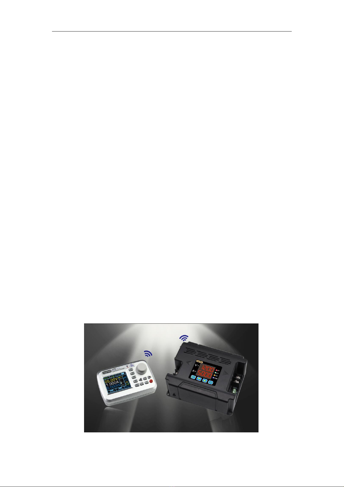
DPM8600 series power supply can be equipped with a wireless control
remote controller. The wireless controller uses a 2.4-inch LCD screen, with
rich display in content, it is simple to operate, with built-in lithium battery,
and it can be recharged. The controller can wirelessly control the switching
power supply within 10 meters, and it can control multiple power supplies at
the same time.
Power supplies can be used in the following fields:
1. Power field, mainly used for integrators and meters, smart meters, LED
drive.
2. Industrial control field.
3. Medical equipment, mainly including tire guards, monitors, etc.
4. Military industry, military equipments.
5. Solar voltage regulation, battery charging and discharging, etc.

Hangzhou Junce Instruments Co., Ltd.
4
Specifications
Model
DPM8605
(DPM8605
-485)
DPM8608
(DPM8608
-485)
DPM8616
(DPM8616
-485)
DPM8624
(DPM8624
-485)
DPM8650
(DPM8650
-485)
Input voltage
10-75V
10-75V
10-75V
10-75V
10-75V
Output voltage
0-60V
0-60V
0-60V
0-60V
0-60V
Output current
0-5A
0-8A
0-16A
0-24A
0-50A
Output power
0-300W
0-480W
0-960W
0-1440W
0-3000W
Communication
Interface
DPM8605, DPM8608, PM8616, DPM8624, DPM8650: TTL
serial communication interface
DPM8605-485, DPM8608-485, DPM8616-485, DPM8624-
485, DPM8650-485: 485 communication interface
Communication
protocol
Free switching between simple communication protocol and
MODBUS communication protocol
Accessories
DPM8605, DPM8608, DPM8616, DPM8624, DPM8650: USB
to TTL cable
DPM8605-485, DPM8608-485, DPM8616-485, DPM8624-
485, DPM8650-485: USB to 485 module
Voltage
resolution
10mV
Current
resolution
1mA
10mA
Output ripple
<50mVpp
Efficiency
92%
Display
accuracy
10mV、1mA
10mV、10mA
Output
tolerance
Voltage: ± 2 ‰ + 1 digit, Current: ± 5 ‰ + 2 digits
Response time
<50ms
Panel Introduction
DPM8624 is taken as an example below. The operation methods of DPM8605,
DPM8608, and DPM8616 are the same as DPM8624. The difference is
decimal places for current display, DPM8605 and DPM8608 current display

Hangzhou Junce Instruments Co., Ltd.
5
three decimal places such as: 3.000, DPM8616, DPM8624 and DPM8650
current display two decimal places such as 03.00.
1. Indicator Introduction
PT: Temperature protection indicator. When the temperature is greater than
80 ℃, the PT light is on, indicating over-temperature protection.
CV: Constant voltage indicator. The CV indicator is on, indicating constant
voltage output.
CC: Constant current indicator. The CC indicator is on, indicating constant
current output.
COM: Communication indicator. When there is a command input, the COM
indicator will be on, indicating normal communication.
2. Module Introduction
Figure 2-1 Illustration of DPM8600 series power supply (DPM8605 / DPM8608)

Hangzhou Junce Instruments Co., Ltd.
6
Table 2-1 DPM8600 series power supply description(DPM8605 / DPM8608)
Item
Description
Item
Description
①
Switch
⑥
Indicator
②
Negative input terminal
⑦
Positive output terminal
③
Positive input terminal
⑧
Negative output terminal
④
LED
⑨
Communication Interface
⑤
Fan
⑩
Function buttons
Figure 2-2 Illustration of DPM8600 series power supply (DPM8616 / DPM8624)

Hangzhou Junce Instruments Co., Ltd.
7
Table 2-2 DPM8600 series power supply description(DPM8616 / DPM8624)
Item
Description
Item
Description
①
Switch
⑥
Indicator
②
Negative input terminal
⑦
Positive output terminal
③
Positive input terminal
⑧
Negative output terminal
④
LED
⑨
Communication Interface
⑤
Fan
⑩
Function buttons
Figure 2-3 Illustration of DPM8600 series power supply (DPM8650)
Table 2-3 DPM8600 series power supply description (DPM8650)
Item
Description
Item
Description
①
Input terminal
⑤
Communication Interface
②
Output terminal
⑥
Fan
③
Function buttons
⑦
Indicator
④
Switch
⑧
LED

Hangzhou Junce Instruments Co., Ltd.
8
3. Display Introduction
Table 2-4 Display description of DPM8600 series power supply
Display
Display content
introduction
Display
Display content
introduction
Denote the voltage value
Denote the current value
Fast discharge ON
Voltage and current upper
limit setting
Communication protocol
Voltage and current lower
limit setting
MODBUS communication
protocol
Cancel the upper and lower
limits of voltage and current
Baud rate selection of 2.4,
4.8, 9.6, 19.2, 38.4, 57.6 and
115.2 unit (Kbps)
Restore factory settings Off
01 group communication
address, 01-99 total 99
communication addresses
Restore factory settings On
Channel 01, a total of 31
communication channels from
00-30, 00 means not
matching with any wireless
controller
Restoring factory settings
Load a parameter in storage
locations 0-9, 1 means first
Power on default no output
Save the parameters to the
storage locations 0-9, 1 meas
first group
Power on default output
Voltage and current display
calibration
Fast discharge Off
Temperature display
Operating Instructions
1. Instructions for Voltage and Current Adjustment and
Shutdown Output:

Hangzhou Junce Instruments Co., Ltd.
9
1. Connect the input and output correctly, and reverse connection is strictly
prohibited. Ensure that the input voltage is within the required range. The
input voltage must be 0.5V or more above the output voltage.
Note: Input voltage range: 10V~75V;
Output current range: 0~5A(DPM8605), 0~8A(DPM8608),
0~16A(DPM8616),0~24A(DPM8624),
0~50A(DPM8650)
Output voltage range: 0~60V.
2. Set the required voltage and current values. It should be noted that the V
digital tube displays the voltage, and the A digital tube displays the current.
After the setting, press OK to turn on the output. At this time, the CV or CC
light is on,indicating that the output is turned on. The method for setting the
voltage and current value is as follows (Blue indicates that the number is
flashing):
The default setting is
5V, 3A at start-up.
Press button shortly,
a value flashes.
The flashing position can
be changed by and
buttons, such as adjusting
12V, 5A. Press to exit
the adjustment state.
Press to turn the output
on or off. When the load
current is less than the set
current, the output is
constant voltage output and
the CV indicator is on.
When the load current
reaches the set current,
the output is the set
current, constant current
output, and the CC
indicator is on.
Press the button
continuously, the flashing
position will move at
different positions of
voltage and current.

Hangzhou Junce Instruments Co., Ltd.
10
2. Store and Load Function Operating Instructions
Press the up or down button on the voltage and current display interface to
enter saving and loading functions, as well as the temperature display and
calibrating functions.
The specific operations are as follows:
Press to
switch to the
below interface.
Pres to
switch to the
below interface.
Press to enter the
0th group of data, and
press the button to
load the group of data.
Press or to enter
the third group of data,
and press the button
to load this group of data.
Press to enter the
9th group of data, and
press the button to
load the group of data.
Press to enter the
0th group of data, and
press the button
to save 12V, 5A to this
group of data.
Press or to
enter the third group of
data, and press the
button to save 12V, 5A
to this group of data.
Press to enter the
9th group of data, and
press the button to
save 12V, 5A to this
group of data.

Hangzhou Junce Instruments Co., Ltd.
11
Corr Calibrating Function Introduction
1.When the set voltage is greater than 20V, for example: set 25V output, but
not connected to the load, the display voltage and the zero point current of
25V is calibrated (that is, the current is calibrated to zero).
2.When the output is turned off, the zero display voltage and zero display
current are calibrated.
3.When the output is short-circuited and the current output is greater than 2A,
for example, if the 3A output is set, the displayed current value of 3A is
calibrated.
Temperature Display and Fan Speed Introduction
The temperature is displayed as the temperature of the current power
device, which can control the fan speed and over-temperature protection.
When the temperature is greater than 40 ℃, the fan starts. For every 5 ℃
increase, the fan speed increases by 1 level. When the temperature reaches
60℃, the fan rotates at the maximum wind speed. When the temperature is
higher than 80 ℃, the product's over-temperature protection will automatically
cut off the output.
3. SET Function Instructions
Press and hold to enter the SET function setting, and then press
shortly to sequentially switch between 1-SA, 2-dF, 3-on, 4-Fd, 5-CS, 6-bd, 7-
Rd, 8-CH. In each function interface, you can use the or button to
change the sub-options in each function setting, and press to confirm the
setting.
The specific content of the display interface, please refer to the following
figure “Display Description”
Press to enter the calibrating
function, and then press the
button to calibrate the displayed
data. For calibrating details, please
refer to the function introduction
below.
Press to observe the
current temperature of
the power device.

Hangzhou Junce Instruments Co., Ltd.
12
The specific operating are following:
Boot default
interface
Press the button
shortly to enter the
factory reset interface.
Use the or
button to change the
sub-options. N means
"No" and Y means
"Yes". Then press
, the setting is
finished.
Press and hold the button
to enter the voltage and current
upper and lower limits saving
interface. Use the or
button to change the sub-options.
The storage location 10
represents the upper limit of the
voltage and current settings, 11
represents the lower limit of the
setting, and 12 represents the
cancellation of the upper and
lower limits. Click , the setting
is finished.
Press the button to enter
the communication protocol
selection interface. Use the
or button to change the
sub-options. 0 means "simple
communication protocol", 1
means "MODBUS communication
protocol", and then press .
The setting is finished.
Press the button to
enter the fast discharge
status interface. Use the
or button to change the
sub-options. 0 means "off",
1 means "on", and then
press the button.The
setting is finished.
Press the button to
enter the power-on
default output status
interface. Use the or
button to change the
sub-options. 0 means
"off", 1 means "on", then
press the button. The
setting is finished.

Hangzhou Junce Instruments Co., Ltd.
13
Voltage and Current Limit Function Introduction:
The upper and lower limit of the voltage and current is to set the upper
and lower limit of the voltage and current adjustment. For example: set 30V,
5A on the main interface, enter the voltage and current upper limit saving
location, and press OK to save them as the voltage and current upper limit.
The maximum voltage adjustment range of the product is 30V and the
maximum current is 5A. The same method can be used to set the lower
adjustment limit.
Communication Protocol Function:
There are two kinds of communication protocols: simple communication
protocol and MODBUS communication protocol, which can be selected on the
product. Communication protocols are provided by our company.
Simple communication protocol is our custom communication protocol. It
is easy to understand.
MODBUS communication protocol is the standard MODBUS
communication protocol.
Quick Discharge Function Introduction:
After the fast discharge is turned on, when the voltage is turned from high
to low, the response time is relatively short.
For example: 30V is being output, and the output is directly adjusted to
5V. When fast discharge is not turned on, it takes 5 seconds to drop from 30V
to 5V, but if the fast discharge is turned on, it takes less than 1 second to drop
from 30V to 5V.
Power-on Default State Settings:
The power-on default state refers to whether the output is turned on or off
by default when the power is turned on. When this function is turned on, the
Press the button shortly to
enter the baud rate selection
interface. There are 7 groups of
baud rates in Kbps. Use the
or button to change the baud
rate, and then press the
button. The setting is finished.
Press the button shortly to enter
the communication address selection
interface. There are a total of 99
communication addresses from 01 to
99. Change the communication
addresses by pressing the or
button, and then press .The
setting is finished.

Hangzhou Junce Instruments Co., Ltd.
14
set voltage and current value will be directly turned on after the power is
turned on without any operation.
Button Lock Function
Pressing and holding the OK button can lock the buttons. When the
button is locked, press and hold the OK button again to cancel the button lock.
Chapter 2 Wireless Controller Instructions
The wireless controller uses 2.4G frequency radio frequency module and wirelessly
transmit signals with the power supply, which can control the power supply within a
range of up to 10 meters. The wireless controller has a built-in 3.7V, 2000mA lithium
battery, which can be recharged repeatedly. It can be used for more than 10 hours
when fully charged. The wireless controller uses a 2.4-inch TFT LCD display, with
multi-function buttons and the knob, parameters can be quickly set and adjusted, and
the operation is simple and fast..
►Note: This remote control is only compatible with DPM8605-RF, DPM8608-RF,
DPM8616-RF, DPM8624-RF, DPM8650-RF, DPM8605-485RF, DPM8608-485RF,
DPM8616-485RF, DPM8624-485RF, DPM8650-485RF models.
Product Specification
Item
Contents
Wireless transmission method
RF transmission
Wireless transmission distance
Within 10 meters (no obstacles)
Communication address
00-99
Communication channel
00-30
Wireless channel
2.4G
Display
2.4 inch TFT LCD display
Rechargeable battery
3.7V/2000mA
Dimension
120*80*25mm
Other manuals for DPM8600 Series
1
Table of contents
Other Juntek Power Supply manuals
Popular Power Supply manuals by other brands

FRONIUS
FRONIUS Selectiva Series quick start guide

Checkpoint
Checkpoint QUANTUM SMART-1 Getting started guide

Control Technologies
Control Technologies 2500 Series quick start guide

Meanwell
Meanwell TDR-480-24 installation manual

Delta
Delta PMC-24V035W1AA instruction manual

qtran
qtran QOM-eLED Series manual