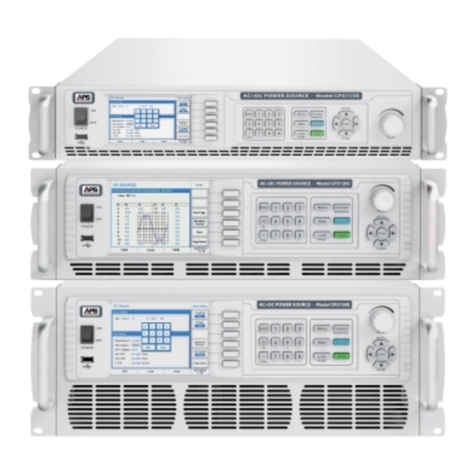
APS DCB Series User manual

Operation Manual
DCB Series – Rev 1.6 P/N 160936-10
DCBSeries
RegerativeDCPowerSupply
ADAPTIVE Power Systems
Worldwide Supplier of Power Equipment
®
Copyright 2018, Adaptive Power Systems, Inc. (APS) • All Rights Reserved • No reproduction without written authorization from APS.

DCB SERIES OPERATION MANUAL
CONTENTS
Entire Contents Copyright 2019 by Adaptive Power Systems, Inc. (APS) • All Rights Reserved • No reproduction without written authorization from APS.
DCB Series DC Power Supply Operation Manual Page 2 of 270
PAGE LEFT INTENTIONALLY LEFT BLANK FOR HARDCOPY VERSIONS OF THIS DOCUMENT

DCB SERIES OPERATION MANUAL
CONTENTS
Entire Contents Copyright 2019 by Adaptive Power Systems, Inc. (APS) • All Rights Reserved • No reproduction without written authorization from APS.
DCB Series DC Power Supply Operation Manual Page 3 of 270
Table of Contents
1Contact Information ...................................................................................................................9
2Warranty, Service and Safety Information ...............................................................................10
2.1 General................................................................................................................................................... 10
2.2 Limited Warranty .................................................................................................................................. 10
2.3 Service and Spare Parts Limited Warranty .......................................................................................... 10
2.4 Equipment Disposal............................................................................................................................... 10
2.5 Safety Information................................................................................................................................. 11
2.6 Safety Notices ........................................................................................................................................ 13
2.6.1 Personal Safety ................................................................................................................................................. 15
2.7 Intended Usage ..................................................................................................................................... 15
3Product Overview.....................................................................................................................16
3.1 General Description............................................................................................................................... 16
3.2 Product Features ................................................................................................................................... 17
3.3 Block Diagram........................................................................................................................................ 17
3.4 Operating Modes .................................................................................................................................. 18
3.4.1 Voltage Regulation or Constant Voltage (CV) Mode ...................................................................................... 18
3.4.2 Current Regulation / Constant Current (CC) Mode ........................................................................................ 19
3.4.3 Power Regulation / Constant Power (CP) Mode ............................................................................................ 20
3.4.4 Internal Resistance (IR) Mode (Source Mode)................................................................................................ 20
3.4.5 Internal Resistance (IR) Mode (Sink Mode)..................................................................................................... 21
3.5 Sink - Source Mode Switching .............................................................................................................. 22
3.6 Alarm Conditions................................................................................................................................... 22
3.6.1 Power Fail.......................................................................................................................................................... 22
3.6.2 Over Temperature Protection ......................................................................................................................... 23
3.6.3 Over Voltage Protection................................................................................................................................... 23
3.6.4 Over Current Protection................................................................................................................................... 23
3.6.5 Over Power Protection..................................................................................................................................... 23
3.7 Accessories Included ............................................................................................................................. 24
3.8 Remote Control Interfaces.................................................................................................................... 25
3.8.1 USB Interface (standard) .................................................................................................................................. 25
3.8.2 Interface Module Slot....................................................................................................................................... 25
3.8.3 Analog Interface................................................................................................................................................ 26
3.8.4 Share Connections............................................................................................................................................ 26
3.8.5 Voltage Sense Connections (Remote Sense) .................................................................................................. 26
3.8.6 Master-Slave Bus .............................................................................................................................................. 26
3.8.7 GPIB Interface Option....................................................................................................................................... 27
3.9 Other Options........................................................................................................................................ 27
4Technical Specifications............................................................................................................28
4.1 2500W Models – 208Vac Input (-2) ..................................................................................................... 28
4.2 5000W Models – 208Vac Input (-2) ..................................................................................................... 31
4.3 7500W Models – 208Vac Input (-2) ..................................................................................................... 34
4.4 5kW 3U HP Models – 208V~480Vac Input (-4).................................................................................... 39
4.5 5kW Models – 380V~480Vac Input (-4)............................................................................................... 39
4.6 10kW 3U HP Models – 208V~480Vac Input (-4).................................................................................. 42
4.7 10kW Models – 380V~480Vac Input (-4)............................................................................................. 43
4.1 15kW 3U HP Models – 208V~480Vac Input (-4).................................................................................. 46
4.2 15kW Models – 380V~480Vac Input (-4)............................................................................................. 47

DCB SERIES OPERATION MANUAL
CONTENTS
Entire Contents Copyright 2019 by Adaptive Power Systems, Inc. (APS) • All Rights Reserved • No reproduction without written authorization from APS.
DCB Series DC Power Supply Operation Manual Page 4 of 270
4.3 30kW Models – 380V~480Vac Input (-4)............................................................................................. 52
4.4 Mechanical Chassis Outlines – 3U Models........................................................................................... 57
4.5 Mechanical Chassis Outlines – 4U Models........................................................................................... 59
5Unpacking and Installation .......................................................................................................62
5.1 Packaging ............................................................................................................................................... 62
5.2 Inspection .............................................................................................................................................. 62
5.3 Ship Kit ................................................................................................................................................... 63
5.4 Check AC Line Voltage........................................................................................................................... 64
5.5 Rear Panel Connections ........................................................................................................................ 64
5.6 AC Input Connections............................................................................................................................ 65
5.6.1 Mains Supply..................................................................................................................................................... 65
5.6.2 Wire Sizing – 208V AC Input “-2” Models........................................................................................................ 65
5.6.3 Wire Sizing – 380V~480V AC Input “-4” Models............................................................................................. 66
5.6.4 AC Line Cord – 208Vac “-2” Models ................................................................................................................ 66
5.6.1 AC Line Cord – 380V~480Vac “-4” Models -15kW.......................................................................................... 66
5.6.2 AC Line Cord – 380V~480Vac “-4” Models -30kW.......................................................................................... 67
5.6.3 Strain Relief and plug fixture............................................................................................................................ 68
5.6.4 Gird Connection Variations.............................................................................................................................. 68
5.6.5 Suggestions for phase assignments:................................................................................................................ 69
5.6.6 Energy Recovery Installation Concept............................................................................................................. 69
5.6.7 AC Input Fuses .................................................................................................................................................. 70
5.7 Grounding Requirements ..................................................................................................................... 71
5.8 Rack Mounting....................................................................................................................................... 71
5.9 Bench Use .............................................................................................................................................. 72
5.10 Loads Connections ................................................................................................................................ 72
5.10.1 Recommended Wire Size................................................................................................................................. 72
5.10.2 DC Terminal Types............................................................................................................................................ 72
5.10.3 Output Cable Safety Covers ............................................................................................................................. 73
5.10.4 DC Output Grounding....................................................................................................................................... 74
5.10.5 Remote Voltage Sense Connections................................................................................................................ 74
5.11 Analog Interface Connections............................................................................................................... 75
5.12 Optional Interface Module Installation................................................................................................ 76
5.12.1 Before Installation ............................................................................................................................................ 76
5.12.2 Procedure.......................................................................................................................................................... 76
5.13 Share Bus Connections.......................................................................................................................... 77
5.14 Slave Units.............................................................................................................................................. 77
5.15 Firmware Update .................................................................................................................................. 78
5.16 Cleaning.................................................................................................................................................. 78
5.17 In Case of Malfunction .......................................................................................................................... 79
6Front Panel Operation ..............................................................................................................80
6.1 Front Panel Layout ................................................................................................................................ 80
6.2 Touch Screen Display ............................................................................................................................ 81
6.2.1 Settings.............................................................................................................................................................. 82
6.2.2 General display and setting ranges:................................................................................................................. 83
6.2.3 Status Display.................................................................................................................................................... 83
6.2.4 Rotary Knob Assignments ................................................................................................................................ 84
6.2.5 Rotary Knob Operation .................................................................................................................................... 84
6.2.6 Available resolutions by voltage models......................................................................................................... 85
6.2.7 Front Panel USB Port ........................................................................................................................................ 85
6.3 Manual Operation................................................................................................................................. 87

DCB SERIES OPERATION MANUAL
CONTENTS
Entire Contents Copyright 2019 by Adaptive Power Systems, Inc. (APS) • All Rights Reserved • No reproduction without written authorization from APS.
DCB Series DC Power Supply Operation Manual Page 5 of 270
6.3.1 Turn On the Power Supply ............................................................................................................................... 87
6.3.2 Turn Off the Power Supply............................................................................................................................... 87
6.3.3 MENU System Overview .................................................................................................................................. 87
6.3.4 Adjustment or User Limits ............................................................................................................................. 102
6.3.5 Changing Operating Modes ........................................................................................................................... 103
6.3.6 Manual Adjustment of Set Values ................................................................................................................. 103
6.3.7 Metering / Read back Displays ...................................................................................................................... 105
6.3.8 Turning Output DC ON or OFF ....................................................................................................................... 105
6.3.9 Saving data to USB Memory Device (Data Logging) ..................................................................................... 106
6.4 Remote Control ................................................................................................................................... 108
6.4.1 General Analog I/O Info.................................................................................................................................. 108
6.4.2 Control Locations............................................................................................................................................ 108
6.4.3 Remote Control using Analog Interface (AI) .................................................................................................109
6.5 Alarms and Monitoring....................................................................................................................... 115
6.5.1 Definition of Terms......................................................................................................................................... 115
6.5.2 Unit Alarm and Event Handling ..................................................................................................................... 115
6.5.3 User defined events........................................................................................................................................ 117
6.6 Front Panel Lockout ............................................................................................................................ 118
6.7 Limits Settings Lock ............................................................................................................................. 119
6.8 Function Generator Use...................................................................................................................... 120
6.8.1 FG Introduction............................................................................................................................................... 120
6.8.2 General FG Description .................................................................................................................................. 120
6.8.3 Method of Operation ..................................................................................................................................... 122
6.8.4 Manual Operation .......................................................................................................................................... 123
6.8.5 Since Wave Function ...................................................................................................................................... 125
6.8.6 Triangular Function......................................................................................................................................... 126
6.8.7 Rectangular Function ..................................................................................................................................... 127
6.8.8 Trapezoidal function....................................................................................................................................... 128
6.8.9 DIN 40839 Function........................................................................................................................................ 129
6.8.10 Arbitrary Function........................................................................................................................................... 130
6.8.11 Ramp Function................................................................................................................................................ 136
6.8.12 UI and IU Table Functions (XY Table)............................................................................................................. 136
6.8.13 PV Table Function (Photovoltaics)................................................................................................................. 138
6.8.14 FC Table Function (Fuel Cell) .......................................................................................................................... 140
6.8.15 Extended PV table function according to EN 50530..................................................................................... 142
6.8.16 Battery Test Function ..................................................................................................................................... 151
6.8.17 MPP tracking function.................................................................................................................................... 156
6.9 Remote Control of the Function Generator....................................................................................... 160
7Remote Control Programming................................................................................................161
7.1 Overview.............................................................................................................................................. 161
7.2 General Comments ............................................................................................................................. 161
7.2.1 Interface Startup Times.................................................................................................................................. 161
7.2.2 Linear Network Topologies ............................................................................................................................ 161
7.2.3 Browser HTTP Access ..................................................................................................................................... 161
7.2.4 TCP Network Access ....................................................................................................................................... 162
7.2.5 General Unit Communication ........................................................................................................................ 162
7.2.6 Message timing and command execution time ........................................................................................... 163
7.3 Communications Protocols Overview................................................................................................ 164
7.3.1 Supported Protocols by Interface Module.................................................................................................... 165
7.3.2 Remote Control Characteristics..................................................................................................................... 165
7.3.3 Fragmented messages on serial transmissions............................................................................................. 166
7.3.4 Connection Timeout....................................................................................................................................... 166
7.3.5 Effective Programming Resolution ................................................................................................................ 166

DCB SERIES OPERATION MANUAL
CONTENTS
Entire Contents Copyright 2019 by Adaptive Power Systems, Inc. (APS) • All Rights Reserved • No reproduction without written authorization from APS.
DCB Series DC Power Supply Operation Manual Page 6 of 270
7.4 Function Generator Minimum Slope .................................................................................................167
7.5 ModBus Protocol.................................................................................................................................168
7.5.1 Preface ............................................................................................................................................................ 168
7.5.2 General ModBus RTU Information................................................................................................................ 168
7.5.3 General ModBus TCP Information................................................................................................................. 168
7.5.4 Format of set values and resolution.............................................................................................................. 168
7.5.5 Translating Set values to Actual values.......................................................................................................... 169
7.6 USB Communication ........................................................................................................................... 169
7.6.1 USB driver installation .................................................................................................................................... 169
7.6.2 First steps ........................................................................................................................................................ 170
7.7 Other Digital Interface Communication............................................................................................. 170
7.8 Register Lists ........................................................................................................................................ 170
7.9 ModBus RTU Details............................................................................................................................ 172
7.9.1 Control Message (write).................................................................................................................................173
7.9.2 Query Message............................................................................................................................................... 174
7.9.3 Response Message (read) .............................................................................................................................. 174
7.9.4 The ModBus Checksum.................................................................................................................................. 177
7.9.5 Communication Errors ................................................................................................................................... 178
7.9.6 Examples of ModBus RTU messages............................................................................................................. 179
7.10 ModBus TCP Details ............................................................................................................................ 182
7.10.1 Example of ModBus TCP messages ............................................................................................................... 182
7.11 Information on Specific Registers....................................................................................................... 183
7.11.1 Register 171 .................................................................................................................................................... 183
7.11.2 Register 408 .................................................................................................................................................... 183
7.11.3 Register 411 .................................................................................................................................................... 183
7.11.4 Registers 500-503 (Set values)....................................................................................................................... 183
7.11.5 Register 505 (Device status)........................................................................................................................... 184
7.11.6 Registers 650 - 662 (Master-slave configuration)......................................................................................... 184
7.11.7 Registers 850 - 6695 (Function generator).................................................................................................... 185
7.11.8 Registers 9000 - 9009 (Adjustment limits) .................................................................................................... 188
7.11.9 Registers 10007 - 10900................................................................................................................................. 189
7.11.10 Register from 11000 (MPP tracking function) .............................................................................................. 189
7.11.11 Register from 12000 (PV simulation / DIN EN 50530).................................................................................. 190
7.12 SCPI Command Language ................................................................................................................... 192
7.12.1 SCPI Examples ................................................................................................................................................. 192
7.12.2 SCPI Command Syntax ................................................................................................................................... 193
7.12.3 SCPI Errors....................................................................................................................................................... 195
7.12.4 Standard IEEE Commands.............................................................................................................................. 195
7.12.5 Status Register ................................................................................................................................................ 196
7.12.6 Set Value Commands ..................................................................................................................................... 199
7.12.7 Measurement Commands ............................................................................................................................. 203
7.12.8 Status commands ........................................................................................................................................... 204
7.12.9 Command for Protective Features ................................................................................................................ 205
7.12.10 Supervisory Commands .................................................................................................................................208
7.12.11 Master/Slave Operation Commands............................................................................................................. 210
7.12.12 Commands for general queries ..................................................................................................................... 211
7.12.13 Unit Configuration Commands ...................................................................................................................... 211
7.12.14 Interface Module Commands (Excl. Ethernet).............................................................................................. 213
7.12.15 Ethernet Interface Commands ...................................................................................................................... 214
7.12.16 Function Generator Commands .................................................................................................................... 215
7.12.17 Commands for remote control of the MPP tracking function .....................................................................221
7.12.18 Alarm Management Commands ................................................................................................................... 223
7.12.19 Commands for Extended PV Simulation ....................................................................................................... 225

DCB SERIES OPERATION MANUAL
CONTENTS
Entire Contents Copyright 2019 by Adaptive Power Systems, Inc. (APS) • All Rights Reserved • No reproduction without written authorization from APS.
DCB Series DC Power Supply Operation Manual Page 7 of 270
7.12.20 Application Examples ..................................................................................................................................... 230
7.13 Profibus & Profinet.............................................................................................................................. 238
7.13.1 General............................................................................................................................................................ 238
7.13.2 Preparation ..................................................................................................................................................... 238
7.13.3 Slot configuration for Profibus....................................................................................................................... 238
7.13.4 Slot configuration for Profinet ....................................................................................................................... 239
7.13.5 Cyclic communication via Profibus/Profinet.................................................................................................240
7.13.6 Acyclic communication via Profibus/Profinet............................................................................................... 240
7.13.7 Examples for acyclic access............................................................................................................................ 241
7.13.8 Data interpretation......................................................................................................................................... 243
7.14 CANopen.............................................................................................................................................. 245
7.14.1 Preparation ..................................................................................................................................................... 245
7.14.2 User objects (indexes) .................................................................................................................................... 245
7.14.3 Translation ADI -> register.............................................................................................................................. 245
7.14.4 Specific examples............................................................................................................................................ 246
7.14.5 Using the arbitrary generator ........................................................................................................................ 246
7.14.6 Error codes...................................................................................................................................................... 247
7.15 CAN Bus................................................................................................................................................ 247
7.15.1 Preparation ..................................................................................................................................................... 247
7.15.2 Introduction .................................................................................................................................................... 248
7.15.3 Message formats ............................................................................................................................................ 248
7.15.4 Message examples ......................................................................................................................................... 254
7.16 EtherCAT .............................................................................................................................................. 256
7.16.1 Introduction .................................................................................................................................................... 256
7.16.2 Integrating your unit in TwinCAT ................................................................................................................... 256
7.16.3 Data objects .................................................................................................................................................... 256
7.16.4 PDOs................................................................................................................................................................ 257
7.16.5 SDOs ................................................................................................................................................................ 257
7.16.6 Use of the data objects................................................................................................................................... 257
8Master/Slave (M/S) Operation ...............................................................................................258
8.1 Parallel Operation................................................................................................................................ 258
8.1.1 Restrictions...................................................................................................................................................... 259
8.1.2 DC Output Wiring Parallel Mode................................................................................................................... 259
8.1.3 Wire Sizing for Share Bus ............................................................................................................................... 259
8.1.4 Wiring and set-up of the Digital Master/Slave bus....................................................................................... 259
8.1.5 Operating a Master/Slave System ................................................................................................................. 261
8.1.6 Alarms and other problem situations............................................................................................................ 262
8.2 Series Operation.................................................................................................................................. 263
8.3 Battery Charging Operation (Source Mode)...................................................................................... 263
9Calibration ..............................................................................................................................264
9.1 Preface ................................................................................................................................................. 264
9.2 Preparation.......................................................................................................................................... 264
9.3 Calibration Procedure ......................................................................................................................... 265
9.3.1 Calibrating Set Values..................................................................................................................................... 265
9.3.2 Calibrating Remote Sense .............................................................................................................................. 265
9.3.3 Calibrating Measurement Values .................................................................................................................. 266
9.3.4 Save Cal Coefficients and Exit......................................................................................................................... 266
10 CE MARK Declaration of Conformity.......................................................................................267
Index…………………………………………………………………………………………………………………………………..268

DCB SERIES OPERATION MANUAL
CONTENTS
Entire Contents Copyright 2019 by Adaptive Power Systems, Inc. (APS) • All Rights Reserved • No reproduction without written authorization from APS.
DCB Series DC Power Supply Operation Manual Page 8 of 270
Table of Tables
Table 3-1: Included Accessories ...........................................................................................................................24
Table 3-2: Available Remote Control Interface Options.......................................................................................25
Table 3-3: Available Options.................................................................................................................................27
Table 5-1: Ship Kit Content ...................................................................................................................................63
Table 5-2: DC Load Wire Size Table ......................................................................................................................72
Table 6-1: USB Memory File Types for Loading....................................................................................................85
Table 6-2: USB Memory File Types for saving ......................................................................................................86
Table 6-3: Analog Interface Specifications .........................................................................................................111
Table 6-4: Alarm Signals .....................................................................................................................................115
Table 6-5: Function Generator Capacities Overview..........................................................................................120
Table 6-6: EN50530 PV Mode Table Variables ...................................................................................................143
Table 6-7: EN50530 PV Test Available Simulation Modes..................................................................................143
Table 7-1: Interface Modules supported Protocols............................................................................................165
Table 7-2: ModBus RTU Functions .....................................................................................................................173
Table 7-3: Supported SCPI Command and Parameter formats ..........................................................................194
Table 7-4: SCPI Error Messages ..........................................................................................................................195
Table of Figures
Figure 3-1: DCB Series Block Diagram ..................................................................................................................17
Figure 3-2: DCB Series Ship Kit Content................................................................................................................24
Figure 5-2: DCB Series Ship Kit Content................................................................................................................63
Figure 5-3: AC Input Mating Connector- (Cable shown not included)..................................................................66
Figure 5-4: AC Input Mating Connector- (Cable shown not included)..................................................................67
Figure 5-5: AC Input Mating Connector-30kW (Cable shown not included) ........................................................67
Figure 5-6: Schematic depiction with one DCB unit and two energy consumers. ...............................................70
Figure 5-7: DC Terminal Types 1 & 2 ....................................................................................................................73
Figure 5-8: External Voltage Sense Connection – 15kW or less ...........................................................................75
Figure 5-9: External Voltage Sense Connection – 30kW ......................................................................................75
Figure 5-10: Effect of Current Slew Rate Settings on Power Supply Testing........................................................79
Figure 6-1: DCB Series Front Panel Views 3U and 4U Models..............................................................................80
Figure 6-2: Main Menu (30kW Models) ...............................................................................................................82
Figure 7-1: SCPI Register Model .........................................................................................................................197

DCB SERIES OPERATION MANUAL
SECTION 1: CONTACT INFORMATION
Entire Contents Copyright 2019 by Adaptive Power Systems, Inc. (APS) • All Rights Reserved • No reproduction without written authorization from APS.
DCB Series DC Power Supply Operation Manual Page 9 of 270
1Contact Information
AMERICA/CANADA
Adaptive Power Systems
Irvine, USA
Phone: +1(949) 752-8400
Fax: +1 (949) 756-0838
Email: support@adaptivepower.com
EUROPE
Caltest Instruments GmbH.
Kappelrodeck, Germany
Phone: +49 7842 99722-00
Fax: +49 7842 99722-29
Email: support@adaptivepower.com
CHINA
PPST Shanghai Co. Ltd.
Shanghai, China
Phone: +86-21-6763-9223
Fax: +86-21-5763-8240
Email: support@adaptivepower.com
Web: http://www.adaptivepower.com

DCB SERIES OPERATION MANUAL
SECTION 2: FRONT MATTER
Entire Contents Copyright 2019 by Adaptive Power Systems, Inc. (APS) • All Rights Reserved • No reproduction without written authorization from APS.
DCB Series DC Power Supply Operation Manual Page 10 of 270
2Warranty, Service and Safety Information
2.1 General
This document is to be kept in either hardcopy of PDF electronic form near the equipment
for future reference and explanation of the operation of the instrument. This document or
its electronic equivalent is to be retained and kept with the equipment in case of change of
location and/or user.
2.2 Limited Warranty
Adaptive Power Systems, Inc. (APS) warrants each unit to be free from defects in material
and workmanship. For the period of three ( 3 ) years from the date of shipment to the
purchaser, APS will either repair or replace, at its sole discretion, any unit returned to the
APS factory in Irvine, California or one of its designated service facilities. It does not cover
damage arising from misuse of the unit or attempted field modifications or repairs. This
warranty specifically excludes damage to other equipment connected to this unit.
Upon notice from the purchaser within (30) days of shipment of units found to be defective
in material or workmanship, APS will pay all shipping charges for the repair or replacement.
If notice is received more than thirty (30) days from shipment, all shipping charges shall be
paid by the purchaser. Units returned on debit memos will not be accepted and will be
returned without repair.
This warranty is exclusive of all other warranties, expressed or implied.
2.3 Service and Spare Parts Limited Warranty
APS warrants repair work to be free from defects in material and workmanship for the
period of ninety (90) days from the invoice date. This Service and Spare Parts Limited
Warranty applies to replacement parts or to subassemblies only. All shipping and packaging
charges are the sole responsibility of the buyer. APS will not accept debit memos for
returned power sources or for subassemblies. Debit memos will cause return of power
sources or assemblies without repair.
This warranty is exclusive of all other warranties, expressed or implied.
2.4 Equipment Disposal
Disposal of this equipment at the end of its technical or economical life must be done in
accordance with local prevailing recycling regulations for electronic waste.

DCB SERIES OPERATION MANUAL
SECTION 2: FRONT MATTER
Entire Contents Copyright 2019 by Adaptive Power Systems, Inc. (APS) • All Rights Reserved • No reproduction without written authorization from APS.
DCB Series DC Power Supply Operation Manual Page 11 of 270
2.5 Safety Information
This chapter contains important information you should read BEFORE attempting to install
and power-up APS Equipment. The information in this chapter is provided for use by
experienced operators. Experienced operators understand the necessity of becoming
familiar with, and then observing, life-critical safety and installation issues. Topics in this
chapter include:
•Safety Notices
•Warnings
•Cautions
•Preparation for Installation
•Installation Instructions
Make sure to familiarize yourself with the SAFETY SYMBOLS shown on the next page. These
symbols are used throughout this manual and relate to important safety information and
issues affecting the end user or operator.

DCB SERIES OPERATION MANUAL
SECTION 2: FRONT MATTER
Entire Contents Copyright 2019 by Adaptive Power Systems, Inc. (APS) • All Rights Reserved • No reproduction without written authorization from APS.
DCB Series DC Power Supply Operation Manual Page 12 of 270
SAFETY SYMBOLS
Direct current (DC)
Alternating current (AC)
Both direct and alternating current
Three-phase alternating current
Off (Supply)
On (Supply)
Protective Earth (ground) terminal
Caution: Refer to this manual before this Product.
Caution, risk of electric shock
Fuse

DCB SERIES OPERATION MANUAL
SECTION 2: FRONT MATTER
Entire Contents Copyright 2019 by Adaptive Power Systems, Inc. (APS) • All Rights Reserved • No reproduction without written authorization from APS.
DCB Series DC Power Supply Operation Manual Page 13 of 270
2.6 Safety Notices
SAFETY SUMMARY
The following general safety precautions must be observed during all phases of operation,
service, and repair of this instrument. Failure to comply with these precautions or with
specific warnings elsewhere in this manual violates safety standards of design, manufacture,
and intended use of the instrument. Adaptive Power Systems assumes no liability for the
customer's failure to comply with these requirements.
GENERAL
This product is a Safety Class 1 instrument (provided with a protective earth terminal). The
protective features of this product may be impaired if it is used in a manner not specified in
the operation instructions.
ENVIRONMENTAL CONDITIONS
This instrument is intended for indoor use in an installation category I, pollution degree 2
environments. It is designed to operate at a maximum relative humidity of 80% and at
altitudes of up to 2000 meters. Refer to the specifications tables for the ac mains voltage
requirements and ambient operating temperature range.
BEFORE APPLYING POWER
Verify that the product is set to match the available line voltage.
GROUND THE INSTRUMENT
This product is a Safety Class 1 instrument (provided with a protective earth terminal). To
minimize shock hazard, the instrument chassis and cabinet must be connected to an
electrical ground. The instrument must be connected to the AC power supply mains through
a properly rated three-conductor power cable, with the third wire firmly connected to an
electrical ground (safety ground) at the power outlet. Any interruption of the protective
(grounding) conductor or disconnection of the protective earth terminal will cause a
potential shock hazard that could result in personal injury.
FUSES
Only fuses with the required rated current, voltage, and specified type (normal blow, time
delay, etc.) should be used. Do not use repaired Fuses or short circuit the fuse holder. To do
so could cause a shock or fire hazard.
DO NOT OPERATE IN AN EXPLOSIVE ATMOSPHERE.
Do not operate the instrument in the presence of flammable gases or fumes.
KEEP AWAY FROM LIVE CIRCUITS.
Operating personnel must not remove instrument covers. Component replacement and
internal adjustments must be made by qualified service personnel. Do not replace
components with power cable connected. Under certain conditions, dangerous voltages

DCB SERIES OPERATION MANUAL
SECTION 2: FRONT MATTER
Entire Contents Copyright 2019 by Adaptive Power Systems, Inc. (APS) • All Rights Reserved • No reproduction without written authorization from APS.
DCB Series DC Power Supply Operation Manual Page 14 of 270
may exist even with the power cable removed. To avoid injuries, always disconnect power,
discharge circuits and remove external voltage sources before touching components.
LETHAL DANGER - HAZARDOUS VOLTAGE
Electrical equipment operation means that some parts can be under hazardous
voltage. Therefore all parts under voltage must be covered! This applies to all
DCB Series models.
All work on connections must be carried out under zero voltage (output not connected to
load) and may only be performed by qualified and informed persons. Improper actions can
cause fatal injury as well as serious material damage.
Never touch cables or connectors directly after unplugging from mains supply as
the danger of electric shock remains!
Never touch the contacts on the DC output terminal directly after switching off
the DC output, because there still can dangerous voltage present, sinking more or less
slowly depending on the load! There also can be dangerous potential between negative DC
output to PE or positive DC output to PE due to charged X capacitors, which may not
discharge.
Always follow these five safety rules when working with electric devices:
1. Disconnect completely
2. Secure against reconnection
3. Verify that the system is dead
4. Carry out earthing and short-circuiting
5. Provide protection from adjacent live parts
DO NOT SERVICE OR ADJUST ALONE.
Do not attempt internal service or adjustment unless another person, capable of rendering
first aid and resuscitation, is present.
DO NOT EXCEED INPUT RATINGS.
This instrument may be equipped with a line filter to reduce electromagnetic interference
and must be connected to a properly grounded receptacle to minimize electric shock
hazard. Operation at line voltages or frequencies in excess of those stated on the data plate
may cause leakage currents in excess of 5.0 mA peak.
DO NOT SUBSTITUTE PARTS OR MODIFY INSTRUMENT.
Because of the danger of introducing additional hazards, do not install substitute parts or
perform any unauthorized modification to the instrument. Return the instrument to an
Adaptive Power Systems Sales and Service Office for service and repair to ensure that safety
features are maintained.
Instruments that appear damaged or defective should be made inoperative and secured
against unintended operation until they can be repaired by qualified service personnel.

DCB SERIES OPERATION MANUAL
SECTION 2: FRONT MATTER
Entire Contents Copyright 2019 by Adaptive Power Systems, Inc. (APS) • All Rights Reserved • No reproduction without written authorization from APS.
DCB Series DC Power Supply Operation Manual Page 15 of 270
OTHER DO’S AND DONT’S
•Do not insert any object, particularly metallic, through the ventilator slots
•Avoid any use of liquids near the equipment. Protect the unit from wet, damp and
condensation.
•Do not connect loads, particularly low resistance, to units under power; sparking
may occur which can cause burns as well as damage to the equipment and to the
user.
•ESD regulations must be applied when plugging interface cards or modules into the
relative slot
•Interface cards or modules may only be attached or removed after the unit is
switched off. It is not necessary to open the unit.
•Do not connect external power sources with reversed polarity to DC input or
outputs! The equipment will be damaged.
•Avoid where possible connecting external power sources to the DC output, and
never those that can generate a higher voltage than the nominal voltage of the unit.
•Never insert a network cable which is connected to Ethernet or its components into
the master- slave socket on the back of the unit!
•Always configure the various protecting features against overvoltage etc. for
sensitive loads to what the target application requires!
2.6.1 Personal Safety
In order to guarantee safety when using the unit, it is essential that only persons operate
the unit who are fully acquainted and trained in the required safety measures to be taken
when working with dangerous electrical voltages
For models which can generate a voltage which is dangerous by contact, or is
connected to such, the included DC terminal cover, or an equivalent, must always
be used
Read and follow all safety warnings in this section
2.7 Intended Usage
This equipment is intended to be used only as a variable voltage and current source. Typical
application for a power supply is to supply precision controlled DC power to any relevant DC
load.
•Claims of any sort due to damage caused by non-intended usage will not be
accepted.
•All damage caused by non-intended usage is the sole responsibility of the operator.

DCB SERIES OPERATION MANUAL
SECTION 3: PRODUCT OVERVIEW
Entire Contents Copyright 2019 by Adaptive Power Systems, Inc. (APS) • All Rights Reserved • No reproduction without written authorization from APS.
DCB Series DC Power Supply Operation Manual Page 16 of 270
3Product Overview
This chapter provides an overview of the APS DCB Series programmable DC power supply
and load combination. It introduces the reader to general operating characteristics of these
power supplies.
3.1 General Description
The APS DCB Series DC power supply is designed to provide accurate, stable and clean DC
power to a unit under test (source mode) as well as absorb power from the unit under test
(sink mode). In sink mode (DC Load), an energy recovery function is utilized which inverts the
consumed DC energy with an efficiency of up to 95% to mains synchronized AC power and feeds it
back into the local mains.
The APS DCB Series power supply can be operated from the front panel (manual mode, also
referred to as Human Machine Interface or HMI) or using and of the available digital or
analog remote control interfaces. Standard interfaces are USB and isolated analog I/O.
Other interfaces can be added as options.
These programmable DC power supplies are especially suitable for test systems and
industrial controls due to their compact construction in a 19” enclosure (3U rack height for
units up to 15kW and 4U rack height for 30kW units). Apart from basic functions of power
supplies, voltage and current set point curves can be generated using the integrated
function generator (sine, rectangular, triangular and other curve types). If needed, arbitrary
generator curves up to 100 points can be saved to and loaded from an USB memory stick.
Some of the functions allow dynamically switching between source and sink operation mode
by setting up positive (for the source) or negative (for the sink) current set values.
Using the optional plug-in digital interface modules, other interfaces such as Profibus,
ProfiNet, ModBus TCP, CAN or CANopen can be added easily. These enable the units to be
connected to standard industrial buses simply by changing or adding a small interface
module. The configuration for each of these, if required at all, is simple.
In addition, the units offer as standard the possibility for parallel connection using a Share
bus master/slave mode for constant current sharing plus a genuine master-slave
connection. Summing of master and slave units measurements by the master is standard.
Operating in this way allows up to 16 units to be combined to a single system with a total
power of up to 480 kW.
All models are controlled by microprocessors. This enables an exact and fast measurement
and display of setting and read back values.
The performance of the DCB Series DC power supply models are detailed in section 4,
“Technical Specifications”. Maximum voltage, current and power capability depends on the
specific model. This manual covers standard DCB Series models. If your unit has a custom
voltage and current range, most of the information in this manual still applies.

DCB SERIES OPERATION MANUAL
SECTION 3: PRODUCT OVERVIEW
Entire Contents Copyright 2019 by Adaptive Power Systems, Inc. (APS) • All Rights Reserved • No reproduction without written authorization from APS.
DCB Series DC Power Supply Operation Manual Page 17 of 270
3.2 Product Features
The following key characteristics apply to all DCB Series models:
•Fully programmable electronic bi-directional (source or sink) DC power supply with
regenerative sink mode for energy recovery.
•Fully remote control of all settings and metering read back.
•Dual high accuracy and high-resolution voltage, current and power meters.
•Constant Power Mode AUTO RANGING Voltage and Current output supports both
high voltage and low current application requirements with a single model.
•Over voltage, current and over power protection.
•External voltage sense.
•Isolated Analog I/O
•Battery Charging Test Modes
•PV Simulation mode
3.3 Block Diagram
The block diagram illustrates the main components inside the unit and their relationships.
There are digital, microprocessor controlled components (Controller, Communication, Front
Panel Interface), which can be the target of firmware updates.
Figure 3-1: DCB Series Block Diagram

DCB SERIES OPERATION MANUAL
SECTION 3: PRODUCT OVERVIEW
Entire Contents Copyright 2019 by Adaptive Power Systems, Inc. (APS) • All Rights Reserved • No reproduction without written authorization from APS.
DCB Series DC Power Supply Operation Manual Page 18 of 270
3.4 Operating Modes
The DCB Series programmable DC power supplies support the following operating modes:
•Constant Voltage (CV) mode
•Constant Current (CC) mode
•Constant Power (CP) mode
•Resistance Mode (sink mode)
Notes:
•When running the unit in source mode, unloaded operation is not considered a
normal operation mode and can thus lead to incorrect measurements. Keep this in
mind when calibrating the unit
•The optimal working point of the unit is between 50% and 100% voltage and current
•It is recommended not to operate the unit below 10% of rated voltage and current
to make sure technical specifications like ripple and transient times can be met.
A power supply is internally controlled by different control or regulation circuits, which shall
bring voltage, current and power to the adjusted values and hold them constant, if possible.
These circuits follow typical laws of control systems engineering, resulting in different
operating modes. Every operating mode has its own characteristics which is explained
below.
3.4.1 Voltage Regulation or Constant Voltage (CV) Mode
In Constant Voltage mode, the DC supply will attempt to maintain precise voltage regulation
regardless of the amount of current demanded by the load. Thus, the power supply
operates as a voltage source. Once the current demanded by the load reaches the current
limit (Imax) or power limit (Pmax) setting value, the power supply will cross over to operate in
constant current or constant power mode, whichever condition occurs first. At this point,
the voltage can’t be held constant anymore and will sink (in source mode) or rise (in sink
mode) to a value resulting from Ohm’s law.
CV is available for both, sink and source mode, and primarily depends on the relation
between voltage set value and voltage level on the DC terminal. The unit will switch
between both modes seamless when adjusting voltage. In source mode, the output voltage
in CV mode is equal to the setting while in sink mode the setting must always be lower than
the input voltage in order to have the unit draw current.
While the DC output is switched on and constant voltage mode is active, the condition “CV
mode active” will be indicated on the display by the abbreviation CV and this message will
be passed as a signal to the analog interface. It is also stored as status condition, which can
be read as a status message via the digital interface.
3.4.1.1 Load step transient times
For constant voltage mode (CV), the technical data “Transient time after load step” (see
Section 4, Technical Specifications) defines a time that is required by the internal voltage

DCB SERIES OPERATION MANUAL
SECTION 3: PRODUCT OVERVIEW
Entire Contents Copyright 2019 by Adaptive Power Systems, Inc. (APS) • All Rights Reserved • No reproduction without written authorization from APS.
DCB Series DC Power Supply Operation Manual Page 19 of 270
control loop of the unit to settle the output voltage in source mode after a load step.
Negative load steps, i.e. high load to lower load, will cause the output voltage to overshoot
for a short time until compensated by the voltage loop. The same occurs with a positive load
step, i.e. low load to high load. The amplitude of the overshoot resp. collapse depends on
the unit model, the currently adjusted output voltage and the capacity on the DC output and
can thus not be stated with a specific value This behavior is illustrated in the figures below.
Example for neg. load step: the DC output will rise above
the adjusted value for a short time. t = transient time to
settle the output voltage.
Example for pos. load step: the DC output will collapse
below the adjusted value for a short time. t = transient
time to settle the output voltage.
3.4.2 Current Regulation / Constant Current (CC) Mode
Constant Current mode is also known as current limiting or current regulation mode. The DC
output current is held constant by the power supply, once the output current (source mode)
to the load, respectively the current consumed by the load (sink mode) reaches the set
current limit. Then the unit automatically switches to CC mode. In source mode, the current
flowing from the unit is determined by the output voltage and the load’s resistance.
As long as the output current is lower than the current limit set point, the unit will be either
in constant voltage or constant power mode. If, however, the power consumption reaches
the maximum power set value Pmax, the unit will switch to power limiting and sets the
output current according to IMAX = Pset / Vin , even if the maximum current value is higher.
The current set point, as determined by the user, is always an upper limit value only.
While the DC output is switched on and constant current mode is active, the condition “CC
mode active” will be indicated on the graphic display by the abbreviation CC and this
message will be passed as a signal to the analog interface. It is also stored as a status
condition, which can be read as a status message via the digital interface.

DCB SERIES OPERATION MANUAL
SECTION 3: PRODUCT OVERVIEW
Entire Contents Copyright 2019 by Adaptive Power Systems, Inc. (APS) • All Rights Reserved • No reproduction without written authorization from APS.
DCB Series DC Power Supply Operation Manual Page 20 of 270
3.4.3 Power Regulation / Constant Power (CP) Mode
Constant Power mode, also known as power limiting or power regulation, keeps the DC
output power constant if the current flowing to the load (source mode), respectively the
current from the source (sink mode) in relation to the output voltage and the resistance of
load reaches the adjusted value according to P = U * I (sink mode) resp. P = U² / R (Source
mode). In source mode, the power limiting then regulates the output current according to I
= SQRT(P / R), where R is the load’s resistance.
Power limiting operates according an auto-range method such
that at lower output voltages, higher current is available and
vice versa in order to maintain a constant output power level
within the range PN(see diagram to the right).
While the DC output is switched on and constant power mode
is active, the condition “CP mode active” will be shown on the
display by the abbreviation CP. It is also stored as a status
condition, which can be read as a status message via digital
interface.
Note: When using remote sensing in source mode, the unit can deliver a higher voltage on
the DC output than adjusted, which results in additional power due to line losses
and may cause the unit to enter power limit condition without explicitly showing
“CP” in the display. In sink mode ,the CP status is correctly displayed for the power
consumed from the source.
3.4.4 Internal Resistance (IR) Mode (Source Mode)
In Internal Resistance mode, the DC supply will not zero load regulate but rather operate the
set voltage point minus a voltage drop determined by the load current and the programmed
internal resistance setting. Thus, the DC supply will simulate having an internal impedance
that causes the output voltage to drop as the load current increases.
= −( ∗)
IR mode is useful for simulating the effects of battery discharge over time by adjusting the
value of Ri as a function of time.
This mode will work in constant current mode as well as in constant power mode, but here
the output voltage will differ even more from the adjusted voltage, because then constant
voltage is not active.
The adjustable resistance range is generally defined between 0 and 30 * UNOM / INOM of the
particular model used. The voltage setting is dependent on the resistance set value and the
output current is obtained by calculation of the microcontroller and thus will be slower the
other controllers inside the control circuit. Clarification:
This manual suits for next models
62
Table of contents
Other APS Power Supply manuals