manuals.online logo
Brands
  1. Home
  2. •
  3. Brands
  4. •
  5. APT
  6. •
  7. Switch
  8. •
  9. APT LW39-25 Series User manual

APT LW39-25 Series User manual

WARNING
Hazardous voltage
can cause electrical shock and burns
Disconnect power before proceeding
with any work on this equipment
Cam Switch LW39-25
EN60947-5-1,GB 14048.5
Instructions
Before installing the device, please read the instructions.
Summary
Main application
LW39-25 switch is also used to controlthestart,brake,
clockwise and anti-clockwise of smallcapacitymotor
and the speed governing of two-speed motor.
General product information:
Model specification
LW 39 - 25 □- □- □···□/ □- □- □- □- □
①②③④⑤⑥⑦⑧⑨⑩⑪
Installation caution
1) We need to check whether the type meetselectionrequirement.
2) We must turn off power before installation and recondition.
3) Wiring refer to drawing and turnon the power after you check
carefully.
4) Choose the correct operational voltage and current.
5) To prevent impurities metal powder into the productinside.
6) Tighten all terminal screws evenif not used.
7) Don't open the parts with red mark.
Technical feature
Parameters
1) Rated insulation voltage(Ui) : 690 V
2) Conventional thermal current(Ith) : 16 A
3) Power frequency withstand voltage : 1890 V / 5 s
4) Mechanical life : 30 X 104times
5) Electrical life : AC / 20 X 104times
DC / 10 X 104times
6) Type of fuse used in test of rated conditional short-circuit
current:NT00-25A
7) The ability of terminals wire:
(1) The largest cross-section: 4 mm²;the maximum number
of conductors connected to the terminal: 2
(2) The largest cross-section: 1 mm²;the maximum number
of conductors connected to the terminal: 2
(3) Tightening torque: 1.2 N·m.
8) Usage category
32017.1
Drawing No. : APT0.463.022.10
Operation condition
1) Environment temperature : -25°C to+55°C
2) Relative air humidity ≤90%
3) Altitude ≤2000 meters
4) Installation category : Ⅲ
5) Pollution class : 3
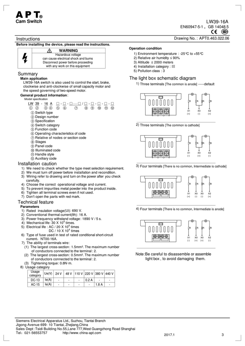
The light box schematic diagram
1) Three terminals [The common is anode] -----default
2) Three terminals [The common is cathode]
3) Four terminals [There is no common, Intermediate is cathode]
4) Four terminals [There is no common, Intermediate is anode]
Note:Be careful to disassemble or assemble
light box, to avoid damaging them.
R R R R
R R R R
X1 X0 X0 X2
X1 X0 X2
R R R R
X1 X0 X2
(+)(-) (-)
(-)(+) (+)
R R R R
X1 X0 X0 X2
(-) (-)(+) (+)
(+) (+)(-) (-)
Siemens Electrical Apparatus Ltd., Suzhou, Tiantai Branch
Jigong Avenue 699- 10 Tiantai, Zhejiang,China
Sales Dept :Tsidi Building No.55,Lane 777,West Guangzhong Road Shanghai
Tel:021-56553757 http://www.china-apt.com
DC-13
AC-15 Ie(A)
Ie(A)
Ue(V)
-
24 V
--
-2.5 A
-
48 V 110 V
1.25 A
12 A
220 V
-
8 A
380 V
AC-21 Ie(A) ----
AC-3 Ie(A) ----12 A
AC-4 Ie(A) ----10 A
AC-22 Ie(A) ----25 A
25 A
Usage
category
①Switch type
②Design number
③Specification
④Function code
⑤Operating characteristics of code
⑥ Relative of nodes orsection code
⑦Stages
⑧Panel code
⑨Illuminated code
⑩Handle style
⑪Auxiliary code
LW39-25
42017.1
Siemens Electrical Apparatus Ltd., Suzhou, Tiantai Branch
Installation
L: The size of the switch body
t : The thickness of the mounting plate
n: The stage of the switch
LW39-25
LW39-25P(LW39-25P2)
LW39-25DM
LW39-25YM(LW39-25PYM)
29.5±1 L=(46+13.5 x n )±2
t=1~3
64±0.5
78±0.5
48±0.2
48±0.2
Ø10
64±0.5
48±0.2
18
5
42
86
2-R2.5
4-Ø4.5
32
29.5±1 L=(32.5+13.5 x n )±2
t=1~3
64±0.5
64±0.5
48±0.2
48±0.2
Ø10
4xØ4.5
42
86
12
10
29.5±1 L=(32.5+13.5 x n )±2 64±0.5
78±0.5
48±0.2
48±0.2
Ø10
4xØ4.5
42
86
12
10
t=1~3
10 6
LW39-25P LW39-25P2
42
86
30±1 64±0.5
64±0.5
27±0.2
60±0.2
42
86
35(The size of guide rail)
2xM5
12
10
L=(72.9+13.5 x n )±2
t=1~3
A(In nature)
78±0.5
42
86
64±0.5
48±0.2
48±0.2
Ø10
4xØ4.5
(45.8)
(113.8)
(124.3)
110.5
100 3248
Ø34
48±0.2
48±0.2
48±0.2
L=(59+13.5 x n )±2
Self-reset=L+13.5
37±1
Ø10
L=(34.6+13.5 x n)±2
64±0.5
4-Ø4.5
Instillation position
t=1~3
64±0.5
Self-reset=L+13.5 Instillation position
LW39-25YS
LW39-25M
LW39-25□□□
L=(49.5+13.5 x n )±2
t=1~3
29.5±1 48±0.2
30±0.2
48±0.2
Ø23
6xØ4.5
42
86
17±1
76±0.5
76±0.5
42
Instillation position
Self-reset=L+13.5
Self-reset=L+13.5
Instillation position
LW39-16NXLCD
LW39-16NXLFD
LW39-16NXTCD
LW39-16NXTFD
LW39-16NXLC
LW39-16NXLF
LW39-16NXTC
LW39-16NXTF
48.5±1
55.5±1
48.5±1
55.5±1
48.5±1
55.5±1
48.5±1
55.5±1
Type Dimension
ARemarks
Pull, A less than 56
Push, A greater
than 48
Push, A greater
than 48
Push, A greater
than 48
Push, A greater
than 48
Self-reset=L+13.5
5
6
7
8
1
2
3
4
No.
Instillation position

This manual suits for next models

8

Other APT Switch manuals

APT LW39-16B User manual

APT

APT LW39-16B User manual

APT LW39-16N Series User manual

APT

APT LW39-16N Series User manual

APT LW39-16A Series User manual

APT

APT LW39-16A Series User manual

APT WorldCast Equinox User manual

APT

APT WorldCast Equinox User manual

Popular Switch manuals by other brands

CTC Union IGS-800C-8PH Quick installation guide

CTC Union

CTC Union IGS-800C-8PH Quick installation guide

Hawking HKS2AU Specifications

Hawking

Hawking HKS2AU Specifications

NETGEAR ProSafe JFS524 installation guide

NETGEAR

NETGEAR ProSafe JFS524 installation guide

Aube Technologies TI033 user manual

Aube Technologies

Aube Technologies TI033 user manual

Allen-Bradley Stratix 5400 user manual

Allen-Bradley

Allen-Bradley Stratix 5400 user manual

Endress+Hauser Liquicap M FTI51 operating instructions

Endress+Hauser

Endress+Hauser Liquicap M FTI51 operating instructions

Vanco Evolution EVSW41KVM quick start guide

Vanco

Vanco Evolution EVSW41KVM quick start guide

Draper KS-3 brochure

Draper

Draper KS-3 brochure

NETGEAR ProSAFE S3300-52X installation guide

NETGEAR

NETGEAR ProSAFE S3300-52X installation guide

HP FlexNetwork 7506X Product End-of-Life Disassembly Instructions

HP

HP FlexNetwork 7506X Product End-of-Life Disassembly Instructions

Allied Telesis AT-8324SX Quick install guide

Allied Telesis

Allied Telesis AT-8324SX Quick install guide

TRENDnet TK-209i Quick installation guide

TRENDnet

TRENDnet TK-209i Quick installation guide

Kramer VP-440H2 quick start guide

Kramer

Kramer VP-440H2 quick start guide

NTI PRIMUX Series Firmware Upgrade Procedure

NTI

NTI PRIMUX Series Firmware Upgrade Procedure

Fracarro Smart Switchline SWI85 STPLUS Series operating instructions

Fracarro

Fracarro Smart Switchline SWI85 STPLUS Series operating instructions

RITS-N TS400 quick start guide

RITS-N

RITS-N TS400 quick start guide

Cisco Catalyst 3850 series Configuration guide

Cisco

Cisco Catalyst 3850 series Configuration guide

TRENDnet TPE-TG160H Quick installation guide

TRENDnet

TRENDnet TPE-TG160H Quick installation guide

manuals.online logo
manuals.online logoBrands
  • About & Mission
  • Contact us
  • Privacy Policy
  • Terms and Conditions

Copyright 2025 Manuals.Online. All Rights Reserved.