Page 2
Contents
1
These parts must be available ............................................................................................................. 2
2
Mounting PS 120-500 M1/M2 ................................................................................................................ 2
2.1
Installation of headstock and access platform for seeder .......................................................... 2
2.2
PS – Installation.......................................................................................................................... 4
3
Dispersion plate assembly and hose routing..................................................................................... 4
3.1
Dispersion plate assembly.......................................................................................................... 4
3.2
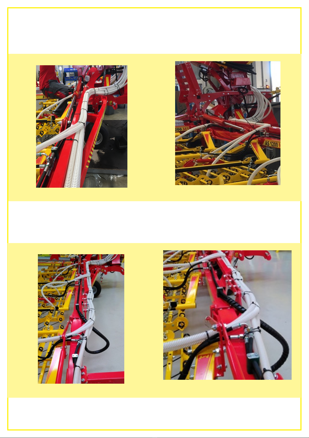
Hose routing ............................................................................................................................... 4
1 These parts must be available
•PS 120 – 500 M1/M2 H 16 A 1 pc.
•07015-2-074 Headstock for seeder 1 pc.
•07015-2-073 MK AS1200 PS120-500 for headstock 1 pc.
•07015-2-014 Access platform for AS 1200 1 pc.
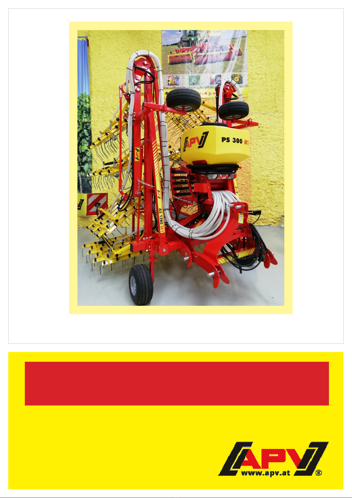
2 Mounting PS 120-500 M1/M2
2.1 Installation of headstock and access platform for seeder
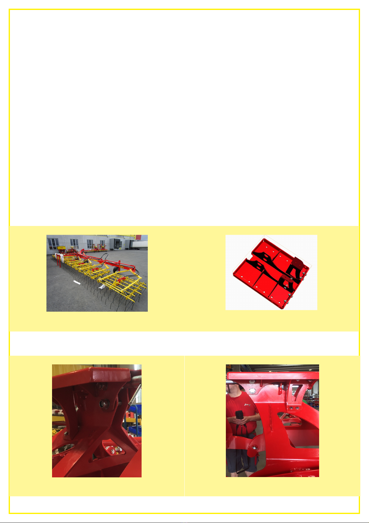
•Unfold the AS 1200 M1 (Figure 1).
•Install the 2 sheet metal profiles on the PS bracket MK AS1200 (Figure 2).
•Install the ABK AS1200 PS120-500 on the headstock of the AS 1200 (Figures 3 and 4).
Figure 1
Figure 2
Figure 4