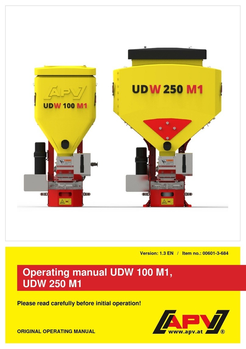
APV UD 100 M1 User manual

ORIGINAL OPERATING MANUAL
Version: 1.0 EN / Item no.: 00601-3-684
Operating manual UD 100 M1
Please read carefully before initial operation!

Page 2
Table of contents
EC Declaration of Conformity...................................................................................................... 3
1 Provisions............................................................................................................................ 4
2 Warranty............................................................................................................................... 4
3 Accident prevention safety instructions............................................................................ 4
4 Mounting of the spreader ................................................................................................... 5
Layout and mode of operation.................................................................................... 5
Mounting the implement............................................................................................. 5
Mounting the control box............................................................................................ 6
5 Settings and operation........................................................................................................ 7
Spreading width ......................................................................................................... 7
Setting charts............................................................................................................. 8
Spreading disc, throwing vanes, point of impact adjustment ...................................... 9
Deflector (guide plate).............................................................................................. 10
Dismounting the seeding shaft................................................................................. 10
Agitator .................................................................................................................... 11
Calibration test / Regulation of the seed rate............................................................ 12
Operation on the road .............................................................................................. 13
Emptying the hopper................................................................................................ 14
6 Cleaning, care, maintenance, and repairs ....................................................................... 14
General information ................................................................................................. 14
Location of the rating plate....................................................................................... 15
Cleaning the spreader.............................................................................................. 15
Repairs and service ................................................................................................. 15
7 Decommissioning, storage and disposal ........................................................................ 16
Decommissioning the implement ............................................................................. 16
Storage of the implement ......................................................................................... 16
Disposal................................................................................................................... 16
8 Technical data ................................................................................................................... 17
9 Accessories ....................................................................................................................... 18
10 Connection diagram.......................................................................................................... 20
11 My idea............................................................................................................................... 21
12 Safety instructions ............................................................................................................ 22
Intended use ............................................................................................................ 22
General safety-related instructions and accident prevention regulations .................. 22
Mounted implements................................................................................................ 24
Maintenance ............................................................................................................ 25
13 Safety signs ....................................................................................................................... 26

Page 3
EC Declaration of Conformity
In compliance with Directive 2006/42/EC
The manufacturer APV - Technische Produkte GmbH
Dallein 15, AT-3753 Hötzelsdorf hereby declares that the product
Universal metering unit UD 100 M1
Implement type designation / serial no. (see handover declaration and title page)
to which this declaration of conformity refers, complies with the relevant basic safety and health
requirements of EC Directive 2006/42 EC as well as the requirements of other relevant EC Directives
2006/42/EC Machinery Directive
2004/108/EC EMC Directive
If applicable: Title / Number / Current version of the other EC Directives
For proper implementation of the safety and health requirements mentioned in the
EC Directives, the following standards and/or technical
specifications were taken into account:
EN 14018 Agricultural and forestry machinery – Seed drills – Safety
EN 349 Safety of machinery – Minimum gaps to avoid crushing of parts of the human body
EN 60204-1 Safety of machinery – Electrical equipment
EN 953 Safety of machinery – Guards
ISO 12100 Safety of machinery – General principles for design –
Risk assessment and risk reduction
ISO 13857 Safety of machinery – Safety distances
ISO 14982 Agricultural and forestry machinery ―Electromagnetic compatibility ―
Test methods and acceptance criteria
If applicable: Title / Number / Current version
Your CE contact person at APV is Mr. Jürgen Schöls.
He can be reached at the telephone number +43(0) 2913-8001.
Dallein, 10/2018
City, Date
Signature
Ing. Jürgen Schöls
Management

Page 4
1 Provisions
Dear customer!
We are pleased and congratulate you on your purchase and wish you lots of fun and success in working
with this implement!
Please be sure to read all the instructions in this operating manual before operating this implement!
2 Warranty
Please check the implement for any transport damage immediately upon receipt. Later claims regarding
transport damage can no longer be considered.
We provide a one-year factory warranty as of the date of delivery (your invoice or the delivery slip serve
as a warranty certificate).
This warranty is applicable for cases of material or construction faults and does not include parts that are
damaged by normal or excessive wear.
The warranty expires
−if damage is caused by external forces.
−in cases of operating errors.
−if the prescribed requirements are not met.
−if the implement is modified, expanded or equipped with third-party spare parts without our
permission.
−if the implement is cleaned with water.
3 Accident prevention safety instructions
The general accident prevention regulations of the respective countries must be observed.
The implement may only be used by persons who are informed of the hazards.
Check the hazard area before starting up and operating the implement! (Children!) Ensure sufficient
visibility!
The warning and information stickers applied to the implement provide important instructions for safe
operation: observe them for the sake of your own safety!
Before starting work, you should get to know all of the equipment and operating elements as well as their
functions.

Page 5
Figure 1: Counter plate
4 Mounting of the spreader
Layout and mode of operation
The UD 100 M1 is a universal spreader with a capacity of 105 litres.
The spread rate is regulated by the seeding shaft, which is driven by a 12V gear motor. The working
width is regulated comfortably from the driver's seat via the speed of the spreading plate.
As an option, there is the possibility of adjusting the speed of the seeding shaft to the speed of the
tractor by using various speed sensors (available as an accessory). Furthermore, tractor linkage sensors
are also available as an option.
Power can be supplied to the control box either through the 3-pin standard socket or optionally directly
from the battery.
Mounting the implement
The spreader should be attached to the vehicle, either
"facing" towards the front or the rear. A steel plate is
riveted onto the frame, which you can bolt on with the
standard supplied counter plate on different parts of the
machine.
To mount the implement on the three-point linkage of
the tractor, bolt the tractor linkage drawbar between your
spreader and the supplied counter plate (Figure 1). To
attach the spreader, you should use at least 8 bolts with
a diameter of 10 mm and the required length to ensure
secure and firm attachment of the implement. Then
install the supplies top link bracket onto the frame of the
spreader.
CAUTION!
APV is not liable for improper mounting or faulty use of the implement.

Page 6
Figure 2
Mounting the control box
Fasten the standard supplied bracket with two bolts in
the tractor cab. Stow the excess cable in the driver's cab
to avoid pinching.
CAUTION!
If possible, do not roll up the cable into a coil!
On the bottom side of the control box, there is a 3-pin
plug (= connection to the power supply of the tractor),
a 6-pin plug (= connection of the spreader to the
control box), and a 12-pin plug for the sensors (speed
sensor and/or lifting unit sensor).
TIP!
Pay attention to the angle at which you
look at the control box to be able to read
the display optimally. If necessary, bend
the bracket slightly to adjust the angle as
required.
The standard supplied cable can be directly
connected to the 3-pin standard socket of the tractor
in the cab. The other end is connected to the control
box.
If your tractor does not have a standard socket, it can
be retrofitted with the cable set included with the
accessories.
The fuse (30 A) is located on the right side of the
control box.
Figure 3

Page 7
CAUTION!
The 12 volt power supply must NOT be connected to the socket for the cigarette lighter.
After use of the implement, the control box should be disconnected again (for various
safety-related reasons).
If your battery is charged by a charger that is in "Start" operating mode, there can be
voltage peaks! These can cause damage to the electrical system of the control box if it is
also connected when the battery is being charged.
CAUTION!
If these instructions are not observed, damage may be caused to the control box.
CAUTION!
After using the implement and for road transport, the control box must be switched off
again (for various safety-related reasons).
5 Settings and operation
Spreading width
The spreading width depends on the density of the de-icing product/salt/grit, on the delivery rate of the
seeding shaft, and the speed of the spreading disc. The snow and ice removal machine is designed
such that it can spread the spreading material evenly across a spreading width of approx. 6 m. The
precise settings for the spread rate, working width etc. can be taken from the setting chart (point 5.2).
We recommend that the spreader be mounted at least 1 m above the ground to achieve a certain degree
of spreading density.
CAUTION!
Make sure that the salt or de-icing product is STORED IN A DRY PLACE, otherwise it can
form clumps in the hopper!
It flows optimally with fine and completely dry salt quality.

Page 8
Setting charts
These tables can be used as reference values. However, they cannot be used in the same way
everywhere as many factors play a role or strong changes can occur (such as the density, spreading
material moisture content, changes in flow behaviour, and much more).
CAUTION!
The grain size of the grit may not exceed 5-6 mm.
Spreading width [m]
1.5 2.5 3 4.5 5 6
Speed for the
spreading disc 200 - 600 600 - 1200
1200 - 1800
1800 - 2400
2400 - 2800
2800 - 3000
Salt
Seeding shaft Calibration quantity
% [kg/min]
2 0.53
5 1.04
10 1.89
15 2.74
20 3.62
25 4.44
30 5.29
35 6.14
40 7.08
45 7.84
50 8.74
55 9.54
60 10.26
65 11.24
70 12.02
75 12.94
80 13.86
85 14.54
90 15.22
95 16.15
99 17.01
100 21.24

Page 9
Figure 4
Positioned towards the front Positioned straight
Positioned towards the rear
Figure 5
Spreading disc, throwing vanes, point of impact adjustment
With the variable throwing vanes
(Figure 4) attached to the spreading
disc, the spread pattern can be
adapted to the specific weight of the
spreading material. This results in
uniform lateral distribution.
When the throwing vanes are moved
forward, the spreading material exits
the spreading disc a little later and the
implement spreads a little more to the
right (when standing in front of the
spreader). When the throwing vanes
are moved back, the spreading
material exits the spreading disc a
little earlier and the implement
spreads a little more to the left (when
standing in front of the spreader).
Moreover, the point of impact can be adjusted. The
point of impact adjustment (Fehler! Verweisquelle
konnte nicht gefunden werden.Figure 5) can be
used to adjust the entire spread pattern by approx.
20° in both directions. This can be important for
some spreading materials, e.g. to avoid having to
adjust the throwing vanes. For example, if the
spreading pattern is turned by 15° to the right, the
point of impact adjustment is turned by 15° to the
left.
To adjust the point of impact, loosen the 4 bolts that
are marked in Figure 5. After making the
adjustment, tighten these bolts again.
PLEASE NOTE!
The seeding shaft can only be switched on when the spreading plate is rotating!

Page 10
Figure 7
Figure 6
Deflector (guide plate)
The deflector is required when the spreading
material is flung towards the front onto the vehicle.
It is installed on the left side in the direction of
travel of the spreader. To install the deflector,
remove the M6x16 flange screw and install the
deflector with the supplied star knob screw.
Dismounting the seeding shaft
To dismount the seeding shaft, proceed as follows:
PLEASE NOTE!
When changing the seeding shaft, ensure that the hopper is completely empty.
After installing the seeding shaft, check the implement for smooth running.
1. Empty the hopper completely.
2.
Loosen the two locking nuts (WAF 10)
marked in Figure 7 and take off the bearing
flange.

Page 11
Figure 8
3. Loosen the star knob screws marked
in Figure 8 and fasten them on the
marked position.
4. Pull the seeding shaft out of the
metering unit in the direction shown by
the arrow (Figure 8).
5. To install the seeding shaft, proceed in
the reverse sequence.
Agitator
Use of the agitator is only required for spreading materials that tend towards bridging.
If the agitator is not needed, then proceed as follows:
1. To remove the motor cover, remove the 6 bolts marked in Figure 9, Figure 10 and Figure 11
Figure 9(WAF 10).
Figure 9: Removing the 3 bolts
Figure 10: Removing the 2 bolts

Page 12
Figure 12: Loosen the nut from the bolt
2. Loosen the nut marked in Figure 12 from the bolt (WAF 7) and pull out the bolt.
3. Reinstall the motor cover on the spreader.
Calibration test / Regulation of the seed rate
The speed of the seeding shaft depends on the spread rate and the forward speed when operating with
sensors. To determine the desired spread rate, you should perform a calibration test before beginning
work.
The spread rate is calculated with the following formula:
Desired spread rate [kg/ha] x forward speed [km/h] x working width [m] = Weight
[kg/min]
600
Example:
Figure 11: Remove the 1 bolt
[kg/min]
1,2
600
[m]12[km/h]12[kg/ha]5 =
×
×

Page 13
Figure
13
Proceed as follows to perform the calibration test:
1. Fold down the spreading plate by opening the quick fasteners
(Figure 13).
2. For the calibration test, use the supplied sack or a different
hopper that can be attached to the metering unit to collect the
spreading material (Figure 14).
3. A precise description of how to perform the calibration test can
be found in the operating manual of your control box.
4. After beginning operation, you should verify the spread rate.
5. In particular, check the forward speed, the spread rate, and
distribution of the spreading material.
CAUTION!
For safety reasons, it is imperative to ensure that the
spreading plate is not switched on as long as the
spreading plate unit is folded down.
Operation on the road
When you start spreading, proceed as follows:
•Start the implement on which the spreading is mounted.
•Switch on the control box using the "On/Off" button.
•Start the spreading plate using the "Spreading plate" button.
•To start the spreading material delivery, now press the "Seeding
shaft" button.
•When the work is finished, first switch off the seeding shaft, then
the spreading plate, and finally the entire control box with the
"On/Off" button.
The following points must be observed during operation:
•The spreading plate should always be switched on during operation.
•Verify the required spread rate!
Figure 14

Page 14
Emptying the hopper
•To empty the hopper, unscrew the screw plug on the emptying
nozzle at the front of the hopper, and hold a container, sack or
other vessel underneath.
•To ensure complete emptying, open the fastener and fold down
the spreading plate.
•Now attach a sack or a suitable hopper to collect the residual
quantity (Figure 15).
•Then actuate the menu point "Emptying" on the control box. Now
let the seeding shaft rotate until the hopper is completely empty,
and the seed wheels no longer deliver spreading material.
TIP!
To remove even the last spreading material residues,
clean out the hopper with compressed air.
Alternatively, you can suck out the remaining
spreading material with an industrial vacuum cleaner.
6 Cleaning, care, maintenance, and repairs
General information
To maintain the implement in good condition even after a long service life, the following instructions must
be observed:
In the supplement "For your safety…" you will find some basic safety regulations for maintenance work.
•Original parts and accessories are designed especially for the machines or implements.
•Please note that parts and accessories not supplied by us have also not been tested and approved
by us.
•The installation or use of such products can therefore possibly negatively change or impede the
constructional properties of your implement. The manufacturer rules out any liability for damages
resulting from the use of non-original parts and accessories.
•The manufacturer is not liable for any unauthorised modifications and the use of components and
auxiliary parts.
•All bolted connections should be re-tightened at the latest after 3 operating hours and again after
20 hours, and then checked regularly. (Loose bolts can cause significant consequential damage,
which is not covered by the warranty.)
Figure 15

Page 15
Figure 16
Location of the rating plate
The rating plate is located on the steel
frame.
In cases of inquiries or warranty claims,
please always tell us the production
number of your machine.
Cleaning the spreader
The spreader must be cleaned inside and out on a regular basis to ensure long-term proper functioning.
If not cleaned properly, germs can form inside the spreader due to spreading material residues. Salt
residues can form clumps when they come into contact with moisture in the hopper.
To clean the spreader:
1. Empty the spreading material hopper (see Emptying the hopper, Point 5.9).
2. Disconnecting the spreader from the power supply.
3. Remove the seeding shaft (see Dismounting the seeding shaft for this, Point 5.5).
4. Fold back the cover of the spreading material hopper to open it.
5. Clean the inside of the spreader and the spreading material paths with compressed air.
6. Clean the outside of the spreader with a moist cloth.
CAUTION!
Ensure that NO WATER enters the hopper or the implement. The inside of the implement
can only be cleaned with compressed air.
The paint can be damaged by cleaning with excessive pressure.
Repairs and service
In case of failure or damage to the spreader, please contact the manufacturer. The contact data can be
found on the last page of this operating manual.

Page 16
7 Decommissioning, storage and disposal
Decommissioning the implement
To ensure that the implement remains fully functional even if it is out of operation for longer periods of
time, it is important to take precautions for storage:
1. Completely remove all spreading material from the spreader.
2. Clean the spreader inside and out (see Cleaning the spreader, Point 6.3).
3. Store the spreader in a dry place to prevent the formation of germs inside the implement.
Storage of the implement
The spreader must be stored in a dry place protected from weather conditions to ensure that it remains
functional even if it is stored for a longer period of time.
Disposal
Disposal of the implement must be performed according to the local disposal regulations for machines.

Page 17
Figure 17 Units in mm
8 Technical data
Designation: UD 100 M1
Hopper content: 105 litres
Weight: 45 kg
Dimensions (H x W x D): 1100 x 550 x 550 mm
Max. spreading width: 6 m with salt
Recommended spreading width: 5 m
Min. spread rate 0.5 kg of salt per minute
Max. spread rate 20 kg of salt per minute
Power supply: 12 V, 30 A
Spreading plate motor data (nominal power): 170 watt
Power consumption of the spreading plate motor: 25 amps when starting,
14 amps during normal operation
Speed range max.: 1500 rpm
Mount category: Cat. II (top link)
Hole pattern on the counter plate:
The contact area must have a minimum dimension of 240 x 140 mm.

Page 18
Figure 18: Truck bed mounting
bracket
Figure
19
: Calibration button
Figure 20: Fill level sensor
9 Accessories
•Truck bed mounting bracket
For practical and easy attachment to flatbeds or pick-up trucks.
Scope of delivery: Truck bed mounting bracket
Item number: 00300-1-001
•Calibration button
The calibration button is integrated directly in the wiring
harness of the universal metering unit. Therefore, the
calibration test can be performed directly from the
spreader.
Scope of delivery: Calibration button
Cable length: 1 m
Item number:00410-2-094
•Fill level sensor
This sensor can be retrofitted on the UD.
It measures the fill level in the hopper and triggers
an alarm on the control box when the set level is
undercut.
The sensitivity of the sensor can be adjusted for
the respective seed type. It is adjusted using the
small slotted screw at the rear of the sensor.
Connect the sensor cable according to the
connection diagram (point 10).
Scope of delivery: Fill level sensor incl.
installation material
Item number: 11000-2-060

Page 19
Figure 21: Shovel bracket
Figure 22: Calibration slide
•Shovel bracket
The shovel bracket can be retrofitted on the UD in order
to carry a snow shovel and/or a broom.
Attention: The snow shovel must not have a handle on
the shaft; if it does it will not fit into the bracket. The
thickness of the shaft must not exceed 41 mm.
Scope of delivery: Brackets incl. rubber grommets
Item number: 11003-2-025
•Calibration slide
The calibration slide is hooked onto the frame.
The parking position for the calibration slide is the
inside of the cover. Here it is firmly held in place
with the rubber clamp (which together with the
necessary attachment parts is included in the
scope of delivery).
Scope of delivery: Calibration slide incl.
rubber clamp
Item number: 11003-2-028

Page 20
10 Connection diagram
Figure 23
Table of contents
Other APV Spreader manuals