Brinly BS-26BH-A User manual

1020135-A1
English Manual
Call Customer Service, Toll-Free: 877-728-8224
Important: This manual contains information for the safety
of persons and property. Read it carefully before
assembly and operation of the equipment!
Visit us on the web!
www.brinly.com
OWNER'S MANUAL
BROADCAST SPREADER
MODELS:
BS-26BH
BS-26BH-A
BS-36BH
BS-36BH-A
• Assembly
• Installation
• Operation
• Repair Parts
For use with Riders
and Lawn / Garden Tractors.
BS-26BH
BS-26BH-A
BS-36BH
BS-36BH-A
21020135-A
English Manual
INTRODUCTION AND SAFETY
CONGRATULATIONS on your new Brinly-Hardy Broadcast Spreader! This accessory has been designed, engineered
and manufactured to give you the best possible dependability and performance.
Should you experience any problem you cannot easily remedy, please do not hesitate to contact our knowledgeable
customer service department toll-free at 1-877-728-8224. We have competent, well trained technicians to help you with
the assembly and use of your product.
CUSTOMER RESPONSIBILITIES
- Please read & retain this manual. The instructions will enable to assemble and maintain your product properly.
- Please carefully read and observe the SAFETY SECTION of this manual.
- Follow a regular schedule in maintaining and caring for your Brinly-Hardy product.
TABLE OF CONTENTS
SAFETY .....................2-4
PARTS
- Hardware Identifier ...........4-5
- Part Lists and Diagrams ........6-8
ASSEMBLY .................. 9-19
USE AND CARE
- Specifications ................21
- Operation ................ 21-22
- Annual Maintenance ........ 23-26
- Flow Settings .............. 27-29
- Troubleshooting .............. 30
- Service .................... 31
WARRANTY .................. 32
REQUIRED TOOLS
FOR ASSEMBLY
• 1/2” Wrench (x2)
• 7/16” Wrench (x2)
• Pliers
• Flat Head Screwdrivers
RECORD PURCHASE INFORMATION
Record your purchase information in
the spaces provided below:
Date of Purchase ______________________________________
Company Name ______________________________________
Company Phone ______________________________________
Serial Number ______________________________________
SAFETY
This symbol will help to point out
important safety precautions throughout this
manual. It means: ATTENTION! BECOME
ALERT! YOUR SAFETY IS INVOLVED.
The machine safety labels shown in this section are placed in
important areas on your machine to draw attention to potential
safety hazards.
On your machine safety labels, the words DANGER, WARNING,
and CAUTION are used with this safety-alert symbol. DANGER
identifies the most serious hazards.
The operator’s manual also explains any potential safety
hazards whenever necessary in special safety messages that
are identified with the word, CAUTION, and the safety-alert
symbol.

1020135-A3
English Manual
SAFETY
- Use this machine for intended purpose only.
- This machine is intended for use in lawn care and home
applications. Do not tow behind a vehicle on a highway
or in any high speed applications. Do not tow at speeds
higher than maximum recommended towing speed.
- Towing speed should always be slow enough to maintain
control. Travel slowly over rough ground.
- Do not let children or an untrained person operate
machine.
- Do not let anyone, especially children, ride on this machine
or the towing vehicle. Riders are subject to injury such
as being struck by foreign objects and being thrown off.
Riders may also obstruct the operator's view, resulting in
this machine being operated in an unsafe manner. Check
towing vehicle brake action before you operate. Adjust or
service brakes as necessary.
- Keep all parts in good condition and properly installed.
Fix damaged parts immediately. Replace worn or broken
parts. Replace all worn or damaged safety and instruction
decals. Do not modify the machine or safety devices.
Unauthorized modifications to the towing vehicle or
machine may impair its function and safety, and void the
warranty.
- Keep all nuts, bolts and screws tight.
OPERATE SAFELY
- Know controls and how to stop quickly, READ THE
VEHICLE OWNER'S MANUAL.
- Do not allow children to operate the vehicle, do not allow
adults to operate without proper instruction or without
having read the owner's manual.
- Do not carry passengers. Keep children and pets a safe
distance away.
- Always wear substantial footwear. Do not wear loose fit-
ting clothing that can get caught in moving parts.
- Use only approved hitches. Tow only with a machine
that has a hitch designed for towing. Do not attach this
machine except at the approved hitch point.
- Keep your eyes and mind on your vehicle & attachment.
Do not let other interests distract you.
- Stay alert for holes in the terrain and other hidden
hazards.
- Do not drive close to creeks, ditches and public
highways.
- Watch out for traffic when crossing or near roadways.
- When using any attachment, don't allow anyone near the
vehicle while in operation.
- Before you operate any feature of this machine, observe
your surroundings and look for bystanders.
- Always wash hands after contact with fertilizers and
pesticides.
- Keep all nuts, bolts and screws tight to be sure the
equipment is in safe working condition.
- The vehicle and attachment should be stopped and
inspected for damage after striking a foreign object.
The damage should be repaired before restarting and
operating the equipment.
- Maximum speed - 3 mph.
- Maintain broadcast spreader tires inflated to 20 psi.
- This attachment is intended for lawn care. Do not tow
behind a vehicle on a highway.
- Avoid tipping and skidding.
- Avoid holes, rocks and roots.
- Slow down before you turn.
- Keep riders off of hitch bracket.
SAFETY RULES
- Always operate your spreader with the speed limit for
which it was designed - 3 MPH.
- When backing - carefully back straight to avoid jack
knifing which could result in damage to equipment.
- Only tow your spreader behind vehicles for which it was
designed - riders, lawn/garden tractors. DO NOT TOW
this spreader behind high speed equipment such as
ATV's, RTV's, or Pick up trucks.
- Do not load the hopper with more than the maximum
weight capacity of 175 pounds for BS-36 and 125 pounds
for BS-26.
OPERATING HINTS
Read the general safety operating precautions in
your towing vehicle operator's manual for additional
safety information.
41020135-A
English Manual
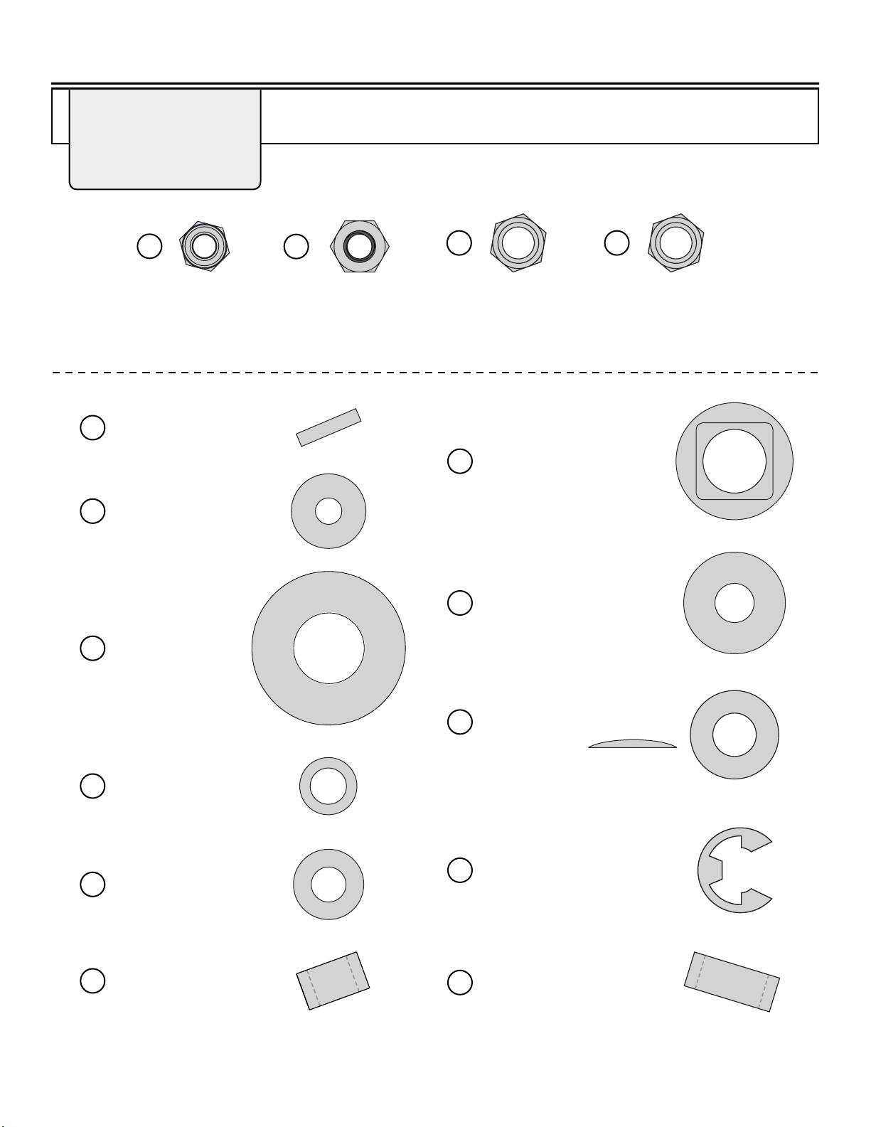
HARDWARE IDENTIFIER
DO NOT RETURN PRODUCT IF YOU ARE MISSING PARTS.
Please Call: 1 (877) 728-8224
Illustrations on this page
are to scale for faster
identication of hardware
during assembly.
E-Ring; Snap 5/8" (x2) . . . . .
F-577
10
Washer; Flat
5/8” (x8) . . . . . .
45M2121P
8
Washer; Flat
5/16” (x8) . . . . . . . . . .
45M1111P
32
Washer; Thrust
1/4” (x6) . . . . . . . . . . .
F-575
3
Bearing; Axle (x2) . . . . . .
F-283
7
5
Nut: Nylon Lock
1/4” (x6)
B-4785
15
Nut; Nylon Lock
5/16” (x5)
B-4786
26
Nut: Hex Head
5/16” -18 (x2)
30M1000P
54
Nut: Hex Lock
5/16” -18 (x2)
B-1674P
O-Ring
3/8” (x1) . . . . . . . . . . . .
F-365
20
Washer; Special (x2) . . . . .
R-618
33
39 Washer; Curved (x1) . . . . . .
F-787
*Side View
Bushing; Pivot (x4) . . . .
F-1045
38 Spacer (x2) . . . . . . . . . . . . . .
1008378-01
42
Pin; Spring (x1) . . . . . . .
F-892
23
1020135-A5
English Manual
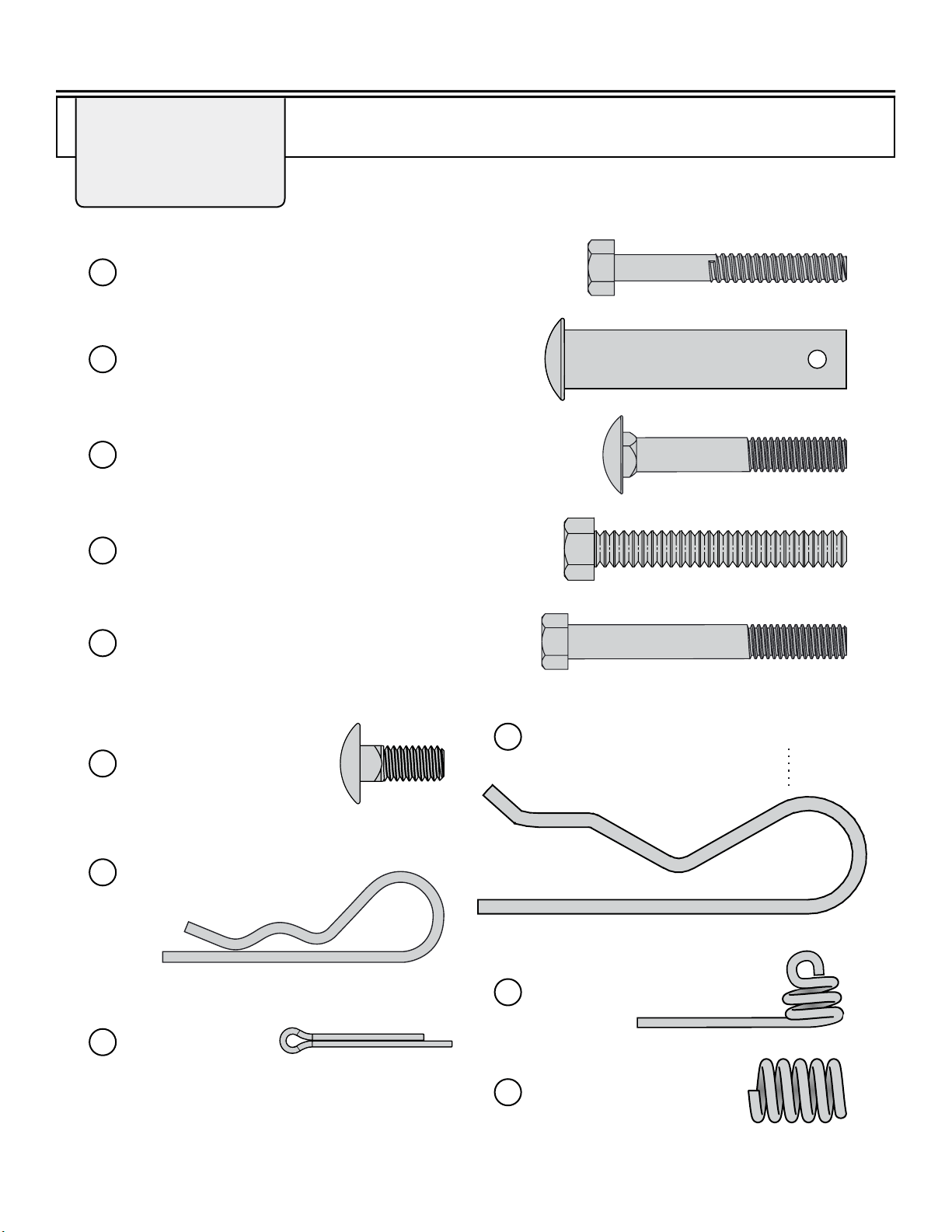
DO NOT RETURN PRODUCT IF YOU ARE MISSING PARTS.
Please Call: 1 (877) 728-8224
HARDWARE IDENTIFIER
Illustrations on this page
are to scale for faster
identication of hardware
during assembly.
Pin; Hitch, 1/2" x 2 1/2" (x1) . . . . . . . . . . . . . . . . . . . . .
B-3861
13
Bolt; Carriage, 5/16 x 2” (x2) . . . . . . . . . . . . . . . . . . . . . . . . . . .
10M1032P
14
Hairpin Cotter
(x1) . . . . . . . . . . . . . . . . .
D-146P
16
Bolt; Carriage
5/16 x 3/4” (x1) . . . . . . . .
11M1012P
41
Bolt; Carriage, 1/4 x 1-3/4” (x6) . . . . . . . . . . . . . . . . . . . . . . .
2M0828SS
4
Bolt; Hex, 5/16 x 2-1/4” (x2) . . . . . . . . . . . . . . . . . . . . . . .
2M1036P-FT
27
Spring (x1) . . . . . . . . . . .
B-3805
34
Spring; Agitator, SS
(x1) . . . . . .
F-436
19
Pin; Cotter
1/8 x 1" (x1) . . . .
50M0416P
18
Bolt; Hex, 5/16 x 2-3/4” (x3) . . . . . . . . . . . . . . . . . . . . .
2M1044P
36
Hairpin Cotter; .148" Diameter
(x1) . . . . . . . . . . . . . . . . . . . . . . .
B-1002P
40

61020135-A
English Manual
COMPONENT VIEW AND REFERENCE LIST
11
31 39
30
29
36
32
32
15
34
35
12
41
33
4
3
2
42
8
7
16
22
32
1
26
40
6
9
10
5
15
27
14
15
28
13
17
17
42
8
7
8
9
10
8
18
21
20
19
25
24
23
32
36
54
32
38
38

1020135-A7
English Manual
COMPONENT VIEW AND REFERENCE LIST
Ref # Part # Description Qty
3F-575 Washer; Thrust, 1/4” 6
42M0828SS Bolt, Hex Stainless, 1/4” x 1-3/4” 6
5B-4785 Nut; Nylon Lock, 1/4” 6
7F-283 Axle; Bearing 2
845M2121P Washer; Flat, 5/8” 8
10 F-577 E-Ring; Snap, 5/8” 2
13 B-3861 Pin; Hitch, 1/2” x 2-1/2” 1
14 10M1032P Bolt, Carriage, 5/16” x 2" 2
15 B-4786 Nut; Nylon Lock, 5/16” 5
16 D-146P Cotter; Hairpin, 1/8” 1
18 50M0416P Pin; Cotter, 1/8” x 1" 1
19 F-436 Spring, Agitator, SS 1
20 F-365 O-Ring; I.D. AS-110, 3/8” 1
22 F-620 Cotter; Special Hairpin 1
24 F-591 Driver; Fan 1
Ref # Part # Description Qty
26 30M1000P Nut; Hex, 5/16”-18 2
27 2M1036P-FT Bolt; Hex, 5/16” x 2-1/4” 2
29 F-782 Knob; 4 Prong, Black 1
32 45M1111P Washer; Flat, 5/16” 8
33 R-618 Washer; Special 2
34 B-3805 Spring 1
35 B-3721 Spacer; Latch 1
36 2M1044P Bolt; Hex, 5/16” x 2-3/4” 3
37 R-1882 Grip; Flat 1
38 F-1045-01 Bushing; Pivot 4
39 F-787 Washer; Crvd. Spring-Glv 1
40 B-1002P Cotter; Hairpin, .148 Diameter 1
41 11M1012P Bolt; Carriage, 5/16” x 3/4” 1
54 B-1674P Nut, Lock, 5/16"-18 2
Skinpack Z-1912 (Used on all models)
Optional Accessory
Hopper Cover
Part Number 1009191
Ref. #
BS-26BH
Part #
BS-26BH-A
Part #
BS-36BH
Part #
BS-36BH-A
Part # Description Qty
1F-1029-10 F-1029-10 F-1029-10 F-1029-10 Hopper Support 1
2F-1030 F-1030 F-1031 F-1031 Hopper 1*
6F-1013-01 F-1013-01 F-1013-01 F-1013-01 Axle; Plated 1
91008774 1008774 1008774 1008774 Wheel; Pneumatic, Composite Rim 2
11 F-1009-10 F-1009-10 F-1009-10 F-1009-10 Plate; Gauge 1
12 F-1010 F-1010 F-1010-01 F-1010-01 Rod; Link 1
17 R-892-10 R-892-10 R-892-10 R-892-10 Clevis 2
21 F-1015 F-1015 F-1015 F-1015 Transmission Assembly 1
23 F-892 F-892 F-892 F-892 Pin; Spring 1
25 F-573 F-573 F-573 F-573 Fan 1
28 F-1023-10 F-1023-10 F-1023-10 F-1023-10 Tube; Tow 1
30 F-781-01 F-781-01 F-781-01 F-781-01 Handle; Stop 1
31 F-1008-10 F-1008-10 F-1008-10 F-1008-10 Handle; Flow Control 1
42 1008378-01 1008378-01 1008378-01 1008378-01 Spacer 2
* The
Hopper
Assembly
Part List
is on
page 8.
** Some models include a Hopper Cover.
81020135-A
English Manual
COMPONENT VIEW AND REFERENCE LIST
Please call our Customer Service
Department, Toll Free: 877-728-8224
Or Email:
customerservice@brinly.com
Installation Questions?
Missing Parts?
Replacement Parts?
STOP
DON’T GO
BACK TO
THE STORE!
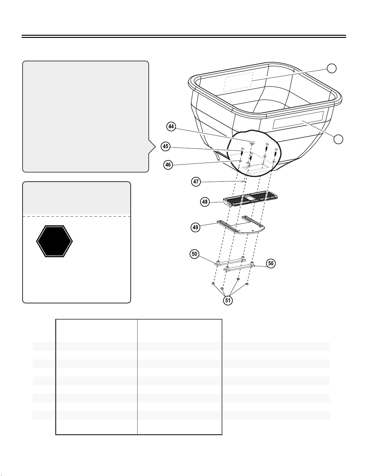
NOTE:
Gate and directional control plate
movement can be adjusted by tightening
/ loosening bolts (45).
The bolts don't require much tightening
or loosening. Use 1/8 turns or less on each
bolt, then test the gate and directional
control plate for your preferred
settings.
Periodically check bolts for tightness.
Ref #
BS-26BH
Part #
BS-26BH-A
Part #
BS-36BH
Part #
BS-36BH-A
Part # Description Qty
44 F-574 F-574 F-574 F-574 Bearing; Shaft 1
45 2M0820SS 2M0820SS 2M0820SS 2M0820SS Bolt; Hex, 1/4” x 1-1/4” SS 4
46 45M0909SS 45M0909SS 45M0909SS 45M0909SS Washer, Plain SS 4
47 F-577 F-577 F-577 F-577 E-Ring, 5/8” 1
48 B-7392 B-7392 B-7392 B-7392 Plate; Directional Control 1
49 B-7391 B-7391 B-7391 B-7391 Gate 1
50 B-7393 B-7393 B-7393 B-7393 Strap 2
51 1005198 1005198 1005198 1005198 Nut; Hex Lock, 1/4”-20 SS 4
52 F-1003 F-1003 F-1003 F-1003 Label; Calibration / Directional 1
53 B-5924 B-5924 B-5924 B-5924 Decal; Logo 1
53
52
1020135-A9
English Manual
ASSEMBLY
Assembly Tip
Illustrations on pages 4 & 5 are to-scale.
For faster identication of the hardware during assembly, simply
lay the hardware on top of these illustrations.
Additional info and videos are available on our website: brinly.com
These QR codes
link directly to the
product pages on our
website.
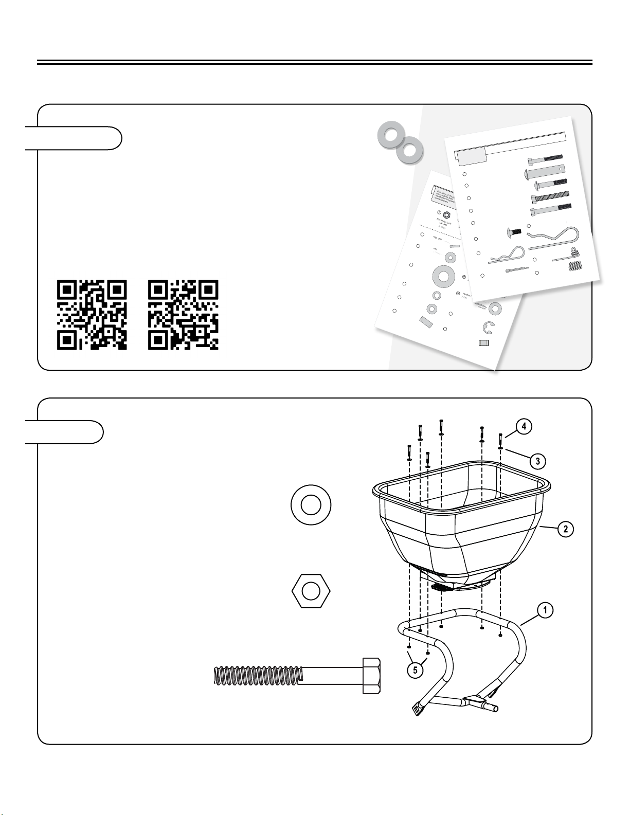
INSTALL HOPPER SUPPORT
TO THE HOPPER
1a. Install six 1/4 x 1-3/4 in.
hex bolts (4), and 1/4 in. thrust
washer (3) through top of
hopper (2) and through support
frame (1), as shown.
1b. Secure bottom of bolt with
1/4 in. lock-nut (5). To avoid
damage to plastic, do not
overtighten hardware.
41020135-A
English Manual
HARDWARE IDENTIFIER
DO NOT RETURN PRODUCT IF YOU ARE MISSING PARTS.
Please Call: 1 (877) 728-8224
Illustrations on this page
are to scale for faster
identication of hardware
during assembly.
E-Ring; Snap 5/8" (x2) . . . . .
F-577
10
Washer; Flat
5/8” (x8) . . . . . .
45M2121P
8
Washer; Flat
5/16” (x 8) . . . . . . . . . .
45 M1111P
32
Washer; Thrust
1/4” (x6) . . . . . . . . . . .
F- 575
3
Bearing; Axle (x2) . . . . . .
F-283
7
5
Nut: Nylon Lock
1/4” (x6)
B- 4785
15
Nut; Nylon Lock
5/16” (x5)
B- 4786
26
Nut: Hex Head
5/16” -18 (x2)
30M1000P
54
Nut: Hex Lock
5/16” -18 (x2)
B- 16 74P
O-Ri ng
3/8” (x 1) . . . . . . . . . . . .
F-365
20
Washer; Special (x2) . . . . .
R- 618
33
39
Washer; Curved (x1) . . . . . .
F-787
*Side View
Bushing; Pivot (x4) . . . . . . . . .
F-104 5
38
Spacer (x2) . . . . . . . .
10083 78-01
42
Pin; Spring (x 1) . . . . . . .
F-892
23
Figure 1
1020135-A
5
English Manual
DO NOT RETURN PRODUCT IF YOU ARE MISSING PARTS.
Please Call: 1 (877) 728-8224
HARDwARE IDENTIFIER
Illustrations on this page
are to scale for faster
identication of hardware
during assembly.
Pin; Hitch, 1/2" x 2 1/2" (x1) . . . . . . . . . . . . . . . . . . . . .
B-38 61
13
Bolt; Carriage, 5/16 x 2” (x2) . . . . . . . . . . . . . . . . . . . . . . . . . . .
10M1032 P
14
Hairpin Cotter
(x1) . . . . . . . . . . . . . . . . .
D-14 6 P
16
Bolt; Carriage
5/16 x 3/4” (x1) . . . . . . . .
11M1 012P
41
Bolt; Carriage, 1/4 x 1-3/4” (x6) . . . . . . . . . . . . . . . . . . . . . . .
2M0828SS
4
Bolt; Hex, 5 /16 x 2-1/4” (x2) . . . . . . . . . . . . . . . . . . . . . . .
2M1036 P-FT
27
Spring (x1) . . . . . . . . . . .
B-3805
34
Sprin g; Agitator, SS
(x1) . . . . . .
F-436
19
Pin; Cotter
1/8 x 1" (x 1) . . . .
50M 0416P
18
Bolt; Hex, 5 /16 x 2-3/4” (x3) . . . . . . . . . . . . . . . . . . . . .
2M104 4P
36
Hairpin Cotter; .148" Diameter
(x1) . . . . . . . . . . . . . . . . . . . . . . .
B-100 2P
40
BS-26BH
BS-26BH-A
BS-36BH
BS-36BH-A
3
Flat Washer (Nylon)
1/4" Qty. 6
5
Lock Nut; Nylon
1/4" Qty. 6
4
Bolt; Hex
1/4" x 1-3/4" Qty. 6

10 1020135-A
English Manual
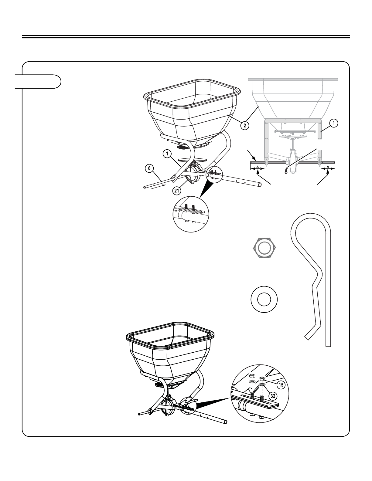
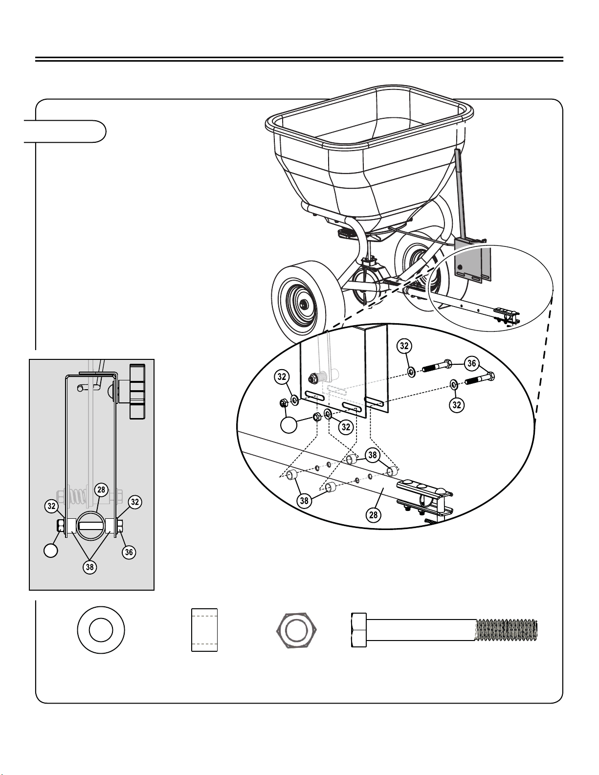
ATTACH TOW TUBE
Attach Tow Tube (28)
to the Hopper Support (1).
Secure using two
5/16” x 2-3/4” Hex Bolts (27)
and two 5/16”-18 Hex
Nuts (26).
ASSEMBLY
ASSEMBLY FAN TO
TRANSMISSION
Slide the Fan Driver (24) and Fan (25) on to
the shaft of the Transmission Assembly (21)
until both reach the Pin Spring (23).
Note: This is for
pre-assembly only.
Final adjustment of the
fan is made later.
Figure 3
Figure 2
27
Bolt Hex, 5/16” x 2-1/4"
Qty. 2
26
Hex Nut, 5/16”
Qty. 2
24
Fan Driver
Qty. 1
1020135-A11
English Manual
ASSEMBLY
INSTALL TRANSMISSION
AND AXLE
4a. Maneuver the transmission
assembly (21) shaft into the
center hole of the Hopper
Assembly (2). Ensure that the
slot of the transmission brace
rests on top of the two tow
tube hex nuts previously
installed in Figure 2, as
shown.
Figure 4
NOTE: Failure to install the
transmission bracket correctly
may void the warranty.
4b. Insert Axle (6) through both Hopper
Support (1) square openings and through
center of transmission assembly (21), as shown.
NOTE: The axle needs to be installed as shown in
order to engage the transmission assembly.
4c. Rotate the axle to line up the hole with the hole in
Transmission assembly hub and insert Hairpin Cotter (40)
4d. Secure the
transmission brace
by attaching two 5/16”
Flat Washers (32) and
two Nylon Lock Nuts (15),
then tighten.
Axle only
goes on one
way Insert Hairpin
Cotter (40)
Back
Install Axle
“A” is equal lengths
on both sides.
32
Flat Washer
5/16” Qty. 2
40
Hairpin
Cotter
Qty. 1
15
Lock Nut, Nylon
5/16” Qty. 2
12 1020135-A
English Manual
ASSEMBLY
INSTALL WHEELS
Attach each Wheel (9) to the
Axle (6) using hardware in the
following order:
• One Axle Bearing (7)
• One Flat Washer 5/8” (8)
• One Spacer (42)
• One or two Flat Washers
5/8” (8) as needed.
• One Composite
Wheel (9)
• One Flat
Washer 5/8” (8)
• One Snapping
E-Ring (10)
Figure 5a
42
Spacer
Qty. 2
15
Axle
Bearing
Qty. 2
8
5/8" Flat
Washer
Qty. 6
10
Snap Ring
E-Type
Qty. 2
Left Wheel
Apply grease to
axle and wheel
bearings
Add or delete Flat
Washer (8) to reduce
Axle side to side
movement.
Left Wheel
1020135-A13
English Manual
ASSEMBLY
Figure 6
FAN ADJUSTMENT
6a. Adjust fan upwards on shaft as close as possible to the bottom
of the hopper without touching during operation.
NOTE: The fan and fan driver normally rests
on the spring pin, but may be adjusted upward
approximately 1/8 of and inch.
If neccesary, adjust fan
upwards on shaft as close
as possible to the bottom
of the hopper without
touching during
operation.
Figure 5b
5b. Secure Axle to the left wheel by inserting Hairpin Cotter
(22) through the wheel hub and axle. NOTE: The axle
may need to be turned in order to line up the hole in the
axle with the hole through the wheel hub.
22
Hairpin Cotter
Qty. 1

14 1020135-A
English Manual
ASSEMBLY
Figure 7
INSTALL AGITATOR
7a. Place O-Ring (20) over transmission
shaft. Slide down to hopper bottom to
create seal.
7c. Insert cotter pin (18) through
spring and the hole at the top of
the transmission shaft. Flair ends
to keep in place.
18
Cotter Pin, 1/8” x 1”
Qty. 1
7b. Slide Agitator
Spring (19) over the
transmission shaft.
19
Agitator Spring
Qty. 1
20
O-Ring 3/8”
Qty. 1

1020135-A15
English Manual
ASSEMBLY
Figure 8
INSTALL CLEVIS
8a. Attach the upper and
lower Clevis (17) halves to
the Tow Tube (28).
Secure with two 5/16” x 2”
Carriage Bolts (14) and two 5/16”
Nylon Hex Nuts (15), as shown.
8b. Insert 1/2” x 2-1/2”
Hitch Pin in to Clevis
and secure.
13
Hitch Pin
1/2” x 2-1/2”
Qty. 1
16
Hairpin
Cotter 1/8”
Qty. 1
14
Carriage Bolt
5/16” x 2”
Qty. 2
15
Nylon Lock
Nut 5/16”
Qty. 2

16 1020135-A
English Manual
ASSEMBLY
Figure 9a
*
36
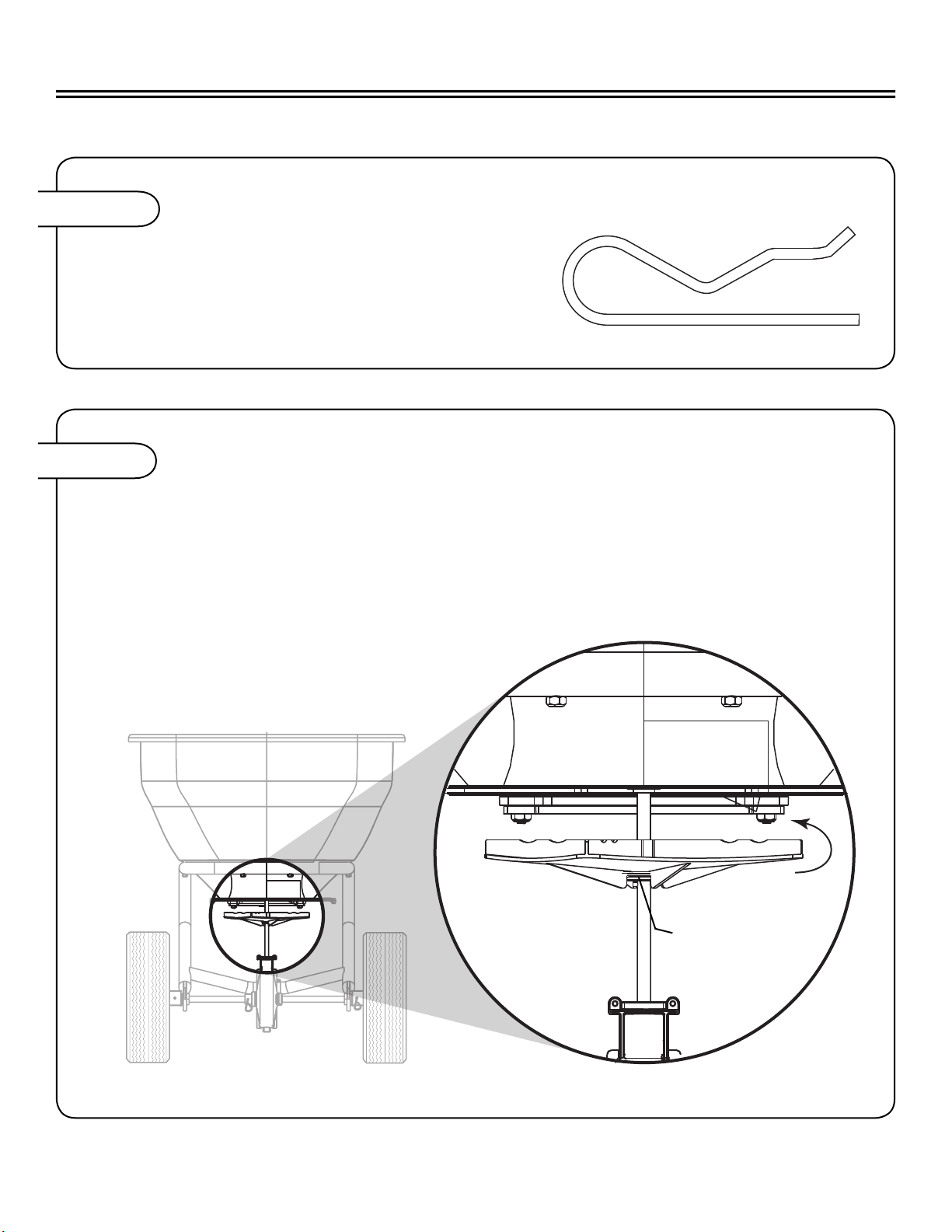
ASSEMBLE GAUGE PLATE
9a. Insert Stop Handle (31) through the slot
opening at the top of the Gauge Plate (11).
9b. Insert the ‘S’ shaped end of Link Rod (12) through the
upper hole of the Flow Control Handle (31).
9c. Assemble Flow Control (31) to Gauge Plate (11) as
shown, using hardware provided:
• One 5/16” x -2-3/4” Hex Bolt (36)
• Two 5/16” Flat Washers (32)
• One Latch Spacer (35)
• Two Special Washers (33)
• One Spring (34)
• One 5/16” Hex Nut (15)
NOTE: See graphic inset below for
hardware orientation.
Gate and handle movement can be adjusted
by tightening/loosening bolt (36).
9d. Attach Handle Stop (30) and Knob (29) as
shown, using hardware provided:
• One 5/16” x 3/4” Carriage Bolt (41)
• One Curved Washer (39).
36
36
36
36
36
15 - Hex Nut
5/16” Qty. 1
34 - Spring
Qty. 1
39 - Washer
Crvd Qty. 1
32 - Washer
5/16” Qty. 2
35 - Spacer,
Latch Qty. 1
33 - Washer
Special Qty. 2
36 - 5/16” x 2-1/4”
Hex Bolt Qty. 1
36

1020135-A17
English Manual
ATTACH GAUGE PLATE
TO SPREADER
10a. Rotate assembled Gauge
Plate (11) approximately
90° clockwise and insert
formed end of the Link
Rod (12) in the hole
provide on the Hopper (10)
control plate, as shown.
10b. Rotate Gauge Plate counter-
clockwise until the handle is
oriented upward and the bottom
of the Gauge Plate is over the
Tow Tube (28).
ASSEMBLY
Figure 10a
Figure 9b
9e. Slide Flat Grip (37) on end of the
Flow control Handle (31).
18 1020135-A
English Manual
ATTACH GAUGE PLATE TO SPREADER
10c. Attach Gauge Plate to the Tow Tube (28)
as shown, using hardware provided:
Do not tighten the hex nuts until after
calibrating the Gauge Plate.
• Two 5/16”x2-3/4” Hex Bolt (36)
• Four 5/16” Flat Washers (32)
• Four Pivot Bushings (38)
• Two 5/16” Hex Lock Nuts (54)
NOTE: See graphic inset below
for hardware orientation.
ASSEMBLY
38
Bushing, Pivot
Qty. 4
36
5/16”x2-3/4” Hex Bolt
Qty. 2
32
Washer, 5/16”
Qty. 4
15
Hex Nut 5/16”
Qty. 2
32
Washer, 5/16"
Qty. 4
38
Bushing, Pivot
Qty. 4
54
Hex Lock Nut 5/16"
Qty. 2
36
5/16" x 2-3/4" Hex Bolt
Qty. 2
38
Bushing, Pivot
Qty. 4
36
5/16”x2-3/4” Hex Bolt
Qty. 2
32
Washer, 5/16”
Qty. 4
15
Hex Nut 5/16”
Qty. 2
54
Figure 10b
38
Bushing, Pivot
Qty. 4
36
5/16”x2-3/4” Hex Bolt
Qty. 2
32
Washer, 5/16”
Qty. 4
15
Hex Nut 5/16”
Qty. 2
54

1020135-A19
English Manual
CALIBRATE GAUGE PLATE
11a. Loosen the knob (29) and
move to the #10, OPEN position,
retighten.
11b. Move Flow Control Handle (31) to
the #10, OPEN position.
11c. Ensure that hopper control gate (48)
opens fully, if not slide the Gauge Plate
(11) forward or backward until control
gate is fully open.
11d. Tighten Gauge Plate securely to theTow
Tube (28) by tightening the hardware
installed in Step 10c.
11e. Move Flow Control Handle to the
CLOSED position, verify hopper control
gate fully closes.
11f Tighten Flow Control
Handle securely to the
Gauge Plate by tightening
hardware assembled in
Step 9c.
Your broadcast
spreader is now ready
for operation.
ASSEMBLY
Figure 11
Assembly is Complete!

20 1020135-A
English Manual
NOTES
NOTES
This manual suits for next models
3
Table of contents
Other Brinly Spreader manuals

Brinly
Brinly PS10-70BH User manual

Brinly
Brinly BSW-20 BH User manual

Brinly
Brinly BS-26BH User manual

Brinly
Brinly AS-40BH User manual

Brinly
Brinly P20-500BH User manual

Brinly
Brinly BTS-150 BH User manual

Brinly
Brinly P20-500BH User manual

Brinly
Brinly BS-36 User manual

Brinly
Brinly AS2-40BH-G User manual

Brinly
Brinly P20-500BH User manual


