5
5. INSTALLATION
7. CLEANING
8. TROUBLESHOOTING
A. Alwaysclean equipment thoroughlybefore first use (See cleaninginstructions).
B. Providethe following clearancesaround foodwarmer:
1. Single model minimum distance to non-combustible surface below = 4 to 10. Dual model
minimum distance to non-combustible surface below = 8 to 14. For combustible surface,
install the singleand dual not closer than 13-1/2to surface below.
2. Minimum distance to side (end) walls = 2.
3. Minimum distance to back walls = 2.
4. Minimum distance to ceiling = 1.
C. Consult foodwarmer rating label for model designation and correct operating voltage and
amperage.
D. Ceiling mounting brackets are provided with each foodwarmer for chain or shelf mounting.
Remove brackets from packaging and screws from ends of foodwarmer to attach brackets.
Use four #10 screws or studs with locknuts for shelf mounting. For chain mounting, use #14 jack
chainand S hooks.
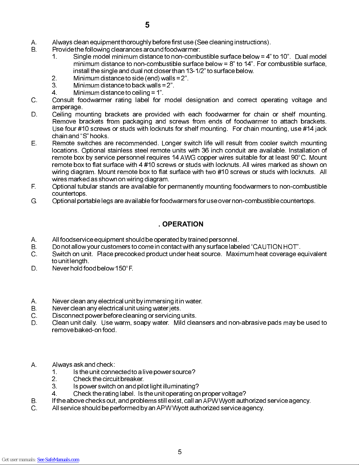
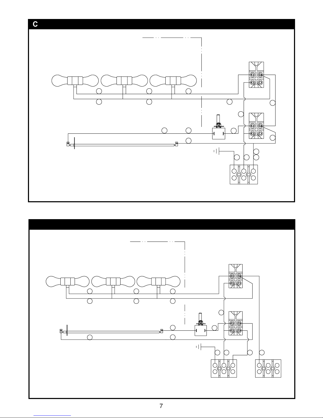
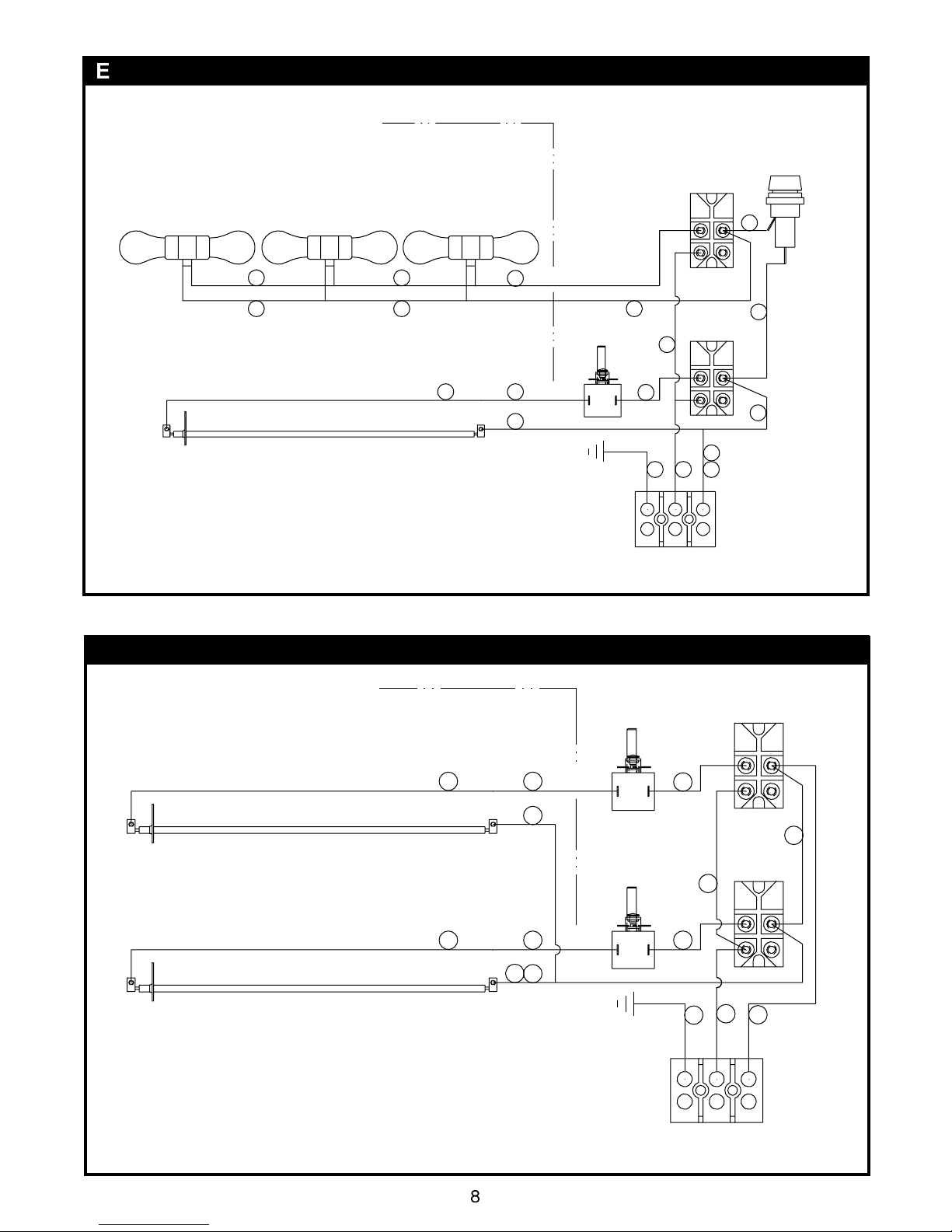
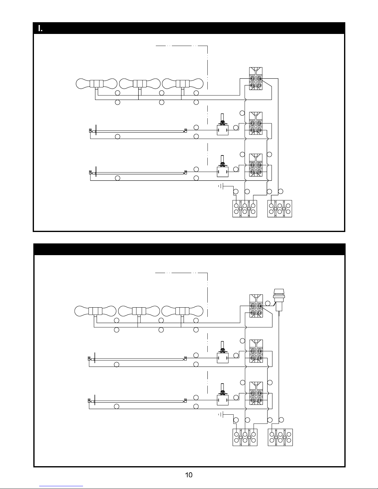
E.
Mount remote box to flat surface with two #10 screws or studs with locknuts. All
wiresmarked as shown on wiring diagram.
F. Optional tubular stands are available for permanently mounting foodwarmers to non-combustible
countertops.
G. Optionalportablelegs are available for foodwarmersfor use over non-combustiblecountertops.
A. Allfoodserviceequipmentshouldbe operated by trained personnel.
B. Do not allow your customersto come in contact with any surface labeled CAUTIONHOT.
C. Switch on unit. Place precooked product under heat source. Maximum heat coverage equivalent
to unit length.
D. Neverhold food below 150°F.
A. Never clean any electricalunit by immersing it in water.
B. Neverclean any electrical unit usingwaterjets.
C. Disconnect power beforecleaning or servicing units.
D. Clean unit daily. Use warm, soapy water. Mild cleansers and non-abrasive pads may be used to
removebaked-on food.
A. Alwaysask and check:
1. Is the unit connected to a live powersource?
2. Checkthe circuit breaker.
3. Is power switch on and pilot lightilluminating?
4. Check the rating label. Is the unit operating on proper voltage?
B. If the above checks out,and problems still exist,call anAPW Wyott authorized service agency.
C. Allserviceshould be performed by anAPWWyott authorizedservice agency.
6. OPERATION
Remote switches are recommended. Longer switch life will result from cooler switch mounting
locations. Optional stainless steel remote units with 36 inch conduit are available. Installation of
remote box by service personnel requires 14 AWG copper wires suitable for at least 90°C. Mount
remote box to flat surface with 4 #10 screws or studs with locknuts. All wires marked as shown on
wiring diagram.
Get user manuals: See SafeManuals.com