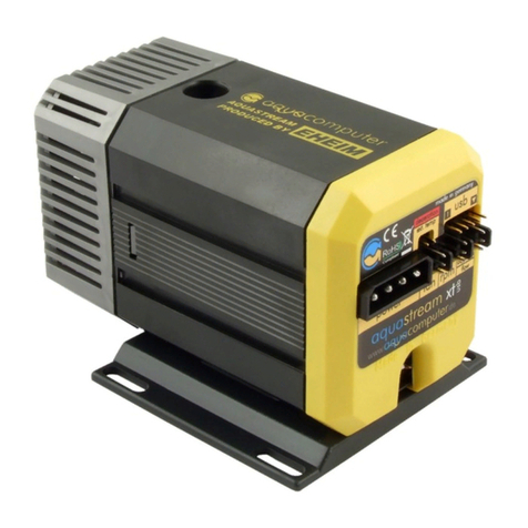
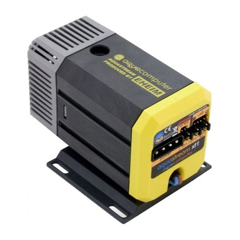
Aqua Computer D5 Operating manual

D5 NEXT
User and installation manual
User and installation manualUser and installation manual
User and installation manual
D5 NEXT
aquasuite version X.17
Current as of April 2020
All information ontained in this manual is subje t to hange without prior noti e.
All rights reserved.
© 2019-2020 Aqua Computer GmbH & Co. KG - 1 -
Gelliehäuser Str. 1, 37130 Glei hen
o
m
p
u
t
e
r
a
q
u
a
ENGLISH: PAGE 1
DEUTSCH: SEITE 31

D5 NEXT
Table of ontents
Table of ontentsTable of ontents
Table of ontents
1. Prefa e.........................................................................................4
2. Safety pre autions.........................................................................4
3. S ope of delivery..........................................................................5
4. Assembly instru tions.....................................................................5
4.1. Deta hable ontrol unit, mounting options......................................5
4.2. Installation to a top/ over or reservoir.............................................6
4.3. Permitted pump orientations...........................................................6
5. Ele tri al onne tions....................................................................6
5.1. Power Conne tor..........................................................................6
5.2. Conne tor “USB”..........................................................................6
5.3. Conne tor “Fan” for fan or flow sensor...........................................7
5.4. Conne tor “Bus” for aquabus or RGBpx..........................................7
6. Operation....................................................................................8
6.1. Operation via keys and display.......................................................8
6.2. Configuration using USB onne tion...............................................8
7. aquasuite software........................................................................8
7.1. Installation of the aquasuite software...............................................8
7.2. Basi operation............................................................................9
7.3. Symbols in the headlines................................................................9
8. Overview pages (aquasuite)...........................................................9
8.1. Desktop mode............................................................................10
8.2. Creating new overview pages and a tivating edit mode..................10
8.3. Adding new elements..................................................................10
8.4. Editing existing elements..............................................................10
8.5. Values and names......................................................................10
8.6. Detailed data elements................................................................11
8.7. Log data hart............................................................................11
8.8. User defined: Images, text, drawing elements.................................11
8.9. Export and import of overview pages.............................................12
9. Data qui k view and data log (aquasuite).....................................12
9.1. Log settings................................................................................12
9.2. Analyze data..............................................................................13
9.3. Manual data export.....................................................................14
9.4. Automati data export.................................................................14
10. Pump onfiguration...................................................................14
10.1. Pump mode power preset..........................................................14
10.2. Pump mode temperature set point..............................................15
10.3. Pump mode urve ontroller......................................................15
10.4. Pump mode flow ontroller........................................................15
10.5. General pump settings..............................................................15
- 2 - Aqua Computer GmbH & Co. KG © 2019-2020
Gelliehäuser Str. 1, 37130 Glei hen
o
m
p
u
t
e
r
a
q
u
a

D5 NEXT
10.6. Pump behavior with aquabus onne tion to an aquaero...............16
11. Fan onfiguration.....................................................................16
11.1. Fan mode power preset.............................................................16
11.2. Fan mode temperature set point.................................................16
11.3. Fan mode urve ontroller.........................................................16
11.4. General fan settings..................................................................17
11.5. Fan behavior with aquabus onne tion to an aquaero..................17
11.6. Dual fun tionality – fan output or flow sensor input.......................17
12. RGBpx onfiguration.................................................................18
12.1. Basi RGBpx settings.................................................................18
12.2. LED mapping...........................................................................18
12.3. Sound ontrolled effe ts.............................................................18
12.4. AMBIENTpx effe t.....................................................................18
13. Sensor onfiguration.................................................................19
13.1. Water temperature sensor..........................................................19
13.2. Options for flow rate measurement.............................................19
13.3. Virtual flow sensor.....................................................................19
13.4. Me hani al flow sensor.............................................................20
13.5. Software temperature sensors.....................................................20
14. Alarm onfiguration..................................................................21
14.1. A ousti alarm and lighting........................................................21
14.2. Alarm reporting and alarm limits................................................21
14.3. System alarms..........................................................................22
15. Display onfiguration and information pages..............................22
15.1. Display settings.........................................................................22
15.2. Charts.....................................................................................23
15.3. Display pages...........................................................................23
16. Profiles.....................................................................................23
16.1. Manual profile sele tion............................................................23
16.2. Automati profile sele tion.........................................................23
16.3. Profile onfiguration..................................................................23
17. System settings D5 NEXT...........................................................23
17.1. Devi e information....................................................................23
17.2. Fa tory defaults........................................................................24
17.3. aquabus/RGBpx onfiguration...................................................24
17.4. Firmware update and language sele tion (aquasuite only).............24
18. Playground (aquasuite)..............................................................24
18.1. Virtual Software Sensors.............................................................24
18.2. Global profiles.........................................................................25
18.3. Hotkeys...................................................................................25
19. aquasuite web..........................................................................26
19.1. Data export..............................................................................26
© 2019-2020 Aqua Computer GmbH & Co. KG - 3 -
Gelliehäuser Str. 1, 37130 Glei hen
o
m
p
u
t
e
r
a
q
u
a

D5 NEXT
19.2. Data a ess.............................................................................26
19.3. Data import..............................................................................27
20. Basi settings (aquasuite)...........................................................27
20.1. Language................................................................................27
20.2. Reorder menu items..................................................................27
20.3. Units.......................................................................................27
20.4. Appli ation start-up...................................................................27
20.5. Servi e administration...............................................................28
20.6. Audio and video.......................................................................28
20.7. Updates and update servi e.......................................................28
21. Te hni al details and are instru tions........................................29
21.1. Te hni al details.......................................................................29
21.2. Restore fa tory defaults..............................................................29
21.3. Care instru tions.......................................................................29
21.4. Waste disposal.........................................................................30
21.5. Conta t Aqua Computer............................................................30
1.
1.1.
1. Prefa e
Prefa ePrefa e
Prefa e
The D5 NEXT pump is built for longevity and to mat h the highest quality stan-
dards. It has been parti ularly designed for PC water ooling systems. The pump is
based on the Laing/Lowara/Xylem D5vario pump and the stainless steel top with
erami ball, the pump rotor and part of the ele troni s and housing are manu-
fa tured by Laing/Lowara/Xylem.
Laing D5 pumps are based on a shaftless spheri al motor: The hemispheri al ro-
tor/impeller unit sits on an ultra-hard, wear-resistant erami ball. Due to its self
adjusting properties, bearing play does not hange even after prolonged use, the
pump keeps on running on a onstantly low noise level.
In addition to the proven hara teristi s of the Laing D5 me hani s, the D5 NEXT
features outstanding monitoring and ontrol options developed by Aqua Comput-
er: The D5 NEXT is equipped with with an integrated fan ontroller for PWM fans,
an USB interfa e as well as either an aquabus interfa e or a RGBpx effe t on-
troller for up to 64 individually addressable LEDs. An OLED display an be used to
visualize urrent sensor readings or to onfigure the pump.
Considering the fast te hni al development, we reserve the right to perform alter-
ations to the produ ts at any time. It therefore is possible that your produ t does
not orrespond pre isely to the des riptions or espe ially the illustrations in this
manual.
2.
2.2.
2. Safety pre autions
Safety pre autionsSafety pre autions
Safety pre autions
The following safety pre autions have to be observed at all times:
●Read this manual thoroughly and entirely!
- 4 - Aqua Computer GmbH & Co. KG © 2019-2020
Gelliehäuser Str. 1, 37130 Glei hen
o
m
p
u
t
e
r
a
q
u
a

D5 NEXT
●Save your data onto suitable media before working on your hardware!
●The pump must not be pla ed under water!
●The pump ontroller on the rear end of the pump must not get in onta t
with water!
●The pump may only be used inside a PC ase!
●The pump is not a su tion pump. Make sure the pump hamber is filled with
water prior to operation!
●The pump is not suited for dry operation!
●This produ t is not designed for use in life support applian es, devi es, or
systems where malfun tion of this produ t an reasonably be expe ted to re-
sult in personal injury. Aqua Computer GmbH & Co. KG ustomers using or
selling this produ t for use in su h appli ation do so at their own risk and
agree to fully indemnify Aqua Computer GmbH & Co. KG for any damages
resulting from su h appli ation!
3.
3.3.
3. S ope of delivery
S ope of deliveryS ope of delivery
S ope of delivery
The following s ope of delivery applies to the retail version only, produ t ode
41118:
●One D5 NEXT pump motor omplete with deta hable ontroller unit, sili-
one damper (repla ement part no. 94694) and mounting plate (repla e-
ment part no. 94766)
●One internal USB able (repla ement part no. 53215)
●One mounting bra ket, bla k (repla ement part no. 94719)
●One sili one insert (repla ement part no. 94695)
●Three s rews M3 x 12 mm, ountersunk head (repla ement part no. 91149)
●Three washers M3 (repla ement part no. 91019)
●Three hexagon nuts M3 (repla ement part no. 91017)
●Four s rews M4 x 8 mm (repla ement part no. 91007)
●Four hexagon nuts M4 (repla ement part no. 91053)
●One manual
4.
4.4.
4. Assembly instru tions
Assembly instru tionsAssembly instru tions
Assembly instru tions
4.1.
4.1.4.1.
4.1. Deta hable ontrol unit, mounting options
Deta hable ontrol unit, mounting optionsDeta hable ontrol unit, mounting options
Deta hable ontrol unit, mounting options
The ontroller unit of the pump an be removed by pulling it off the pump motor
unit in a straight line. Make sure that no power is supplied to the pump whenever
the ontroller unit is being removed from or re-atta hed to the pump motor unit!
The ontroller unit an only be atta hed to the pump motor unit in a given orienta-
tion. Do not use ex essive for e but re- he k the orientation if you en ounter
problems re-atta hing the ontroller unit.
The pump may be installed into the PC ase using the supplied sili one damper
and mounting plate, either to a level surfa e or – using the supplied 90° bra ket –
© 2019-2020 Aqua Computer GmbH & Co. KG - 5 -
Gelliehäuser Str. 1, 37130 Glei hen
o
m
p
u
t
e
r
a
q
u
a

D5 NEXT
to a verti al surfa e. If these mounting options are not used, the sili one damper
of the pump an be repla ed with a flat sili one insert.
Please note that all mounting options that make use of the sili one damper require
the pump to be installed verti ally above the damper and are not designed to
withstand lateral stress or transportation of the PC!
4.2.
4.2.4.2.
4.2. Installation to a top/ over or reservoir
Installation to a top/ over or reservoirInstallation to a top/ over or reservoir
Installation to a top/ over or reservoir
For operation of the pump, a ompatible top/ over is required, alternatively the
pump may be installed dire tly to a ompatible reservoir. In both ases, the pump
motor will be held in pla e by fixation rings to be slid over the pump. In order to
do so, deta h the ontroller unit from the pump motor unit, fasten the pump motor
using the fixation ring and re-atta h the ontroller unit.
4.3.
4.3.4.3.
4.3. Permitted pump orientations
Permitted pump orientationsPermitted pump orientations
Permitted pump orientations
During operation, the impeller of the pump must be dire ted upwards or to the
side relative to the ontroller unit. Operation with downwards oriented, “hanging”
impeller is not permitted!
5.
5.5.
5. Ele tri al onne tions
Ele tri al onne tionsEle tri al onne tions
Ele tri al onne tions
ATTENTION: Completely turn off your power supply or dis onne t the mains pow-
er ord from the wall outlet before onne ting or dis onne ting any ables to/from
the devi e!
5.1.
5.1.5.1.
5.1. Power Conne tor
Power Conne torPower Conne tor
Power Conne tor
Conne t a SATA power plug of your PC's power supply unit to this onne tor. Do
not use ex essive for e but double he k the polarity of the plug if you are having
trouble to onne t.
Pin assignment: Pin 1, 2, 3, 11: not onne ted
Pin 4, 5, 6, 10, 12: GND
Pin 7, 8, 9: 5 V DC
Pin 13, 14, 15: 12 V DC
5.2.
5.2.5.2.
5.2. Conne tor “USB”
Conne tor “USB”Conne tor “USB”
Conne tor “USB”
This onne tor is used for USB ommuni ation with a PC. Conne t to an internal
USB header of your motherboard. Take spe ial are to make sure the pin align-
ment mat hes your motherboard! The USB interfa e is used for data ex hange
with the PC and not required for pump operation.
The orresponding onne tor on the motherboard is usually
a 9 pin onne tor with two independent USB ports. Both
rows of 4/5 pins an be used to onne t an USB devi e.
- 6 - Aqua Computer GmbH & Co. KG © 2019-2020
Gelliehäuser Str. 1, 37130 Glei hen
o
m
p
u
t
e
r
a
q
u
a

D5 NEXT
The bla k wires (GND) are to be onne ted to the side of the missing pin, see pi -
ture with olored pin assignment.
Pin assignment: Pin 1: GND (bla k, optional)
Pin 2: GND (bla k)
Pin 3: D+ (green)
Pin 4: D- (white)
Pin 5: +5 V(red)
5.3.
5.3.5.3.
5.3. Conne tor “Fan” for fan or flow sensor
Conne tor “Fan” for fan or flow sensorConne tor “Fan” for fan or flow sensor
Conne tor “Fan” for fan or flow sensor
Depending on onfiguration, this onne tor an either be used as a PWM regulat-
ed fan output with speed signal pro essing or to onne t a flow sensor. Simultane-
ous use of both fun tions is not possible!
Pin assignment: Pin 1: GND
Pin 2: 12 V / max. 25 W
Pin 3: Speed signal
Pin 4: PWM signal
Flow sensor and spe ial inter onne ting able are optional a essories and not in-
luded in delivery.
Compatible flow sensors:
●Flow sensor with 5.6 mm nozzle (53061)
●Flow sensor “high flow” (53068)
●Conne tion able for flow sensor (53027, 53100)
5.4.
5.4.5.4.
5.4. Conne tor “Bus” for aquabus or RGBpx
Conne tor “Bus” for aquabus or RGBpxConne tor “Bus” for aquabus or RGBpx
Conne tor “Bus” for aquabus or RGBpx
Depending on onfiguration, this onne tor an either be used for ommuni ation
with other Aqua Computer devi es or to onne t RGBpx produ ts (up to 90 ad-
dressable LEDs). Simultaneous use of both fun tions is not possible!
Compatible aquabus devi es:
●aquaero 6 XT (53146, 53206, 53250, 53251, 53262, 53263)
●aquaero 6 PRO (53145, 53253)
●aquaero 6 LT (53234)
●aquaero 5 XT (53089, 53125, 53249)
●aquaero 5 PRO (53090, 53252)
●aquaero 5 LT (53095)
If the RGBpx produ t to be onne ted has more than one RGBpx onne tor, the
onne tor marked with the word “IN” must be used! Additional RGBpx produ ts
may be onne ted to the “OUT” onne tor.
Compatible RGBpx produ ts:
●RGBpx LED-Strip (53268, 53269, 53270)
●RGBpx lighting set (53271, 53272)
●RGBpx Splitty4 (53267)
●RGBpx LED ring for ULTITUBE (34115)
© 2019-2020 Aqua Computer GmbH & Co. KG - 7 -
Gelliehäuser Str. 1, 37130 Glei hen
o
m
p
u
t
e
r
a
q
u
a

D5 NEXT
●RGBpx LED ring for aqualis (53274, 53276)
●RGBpx LED ring for 60 mm reservoir (53277)
●RGBpx able (53259, 53260, 53261, 53266)
6.
6.6.
6. Operation
OperationOperation
Operation
6.1.
6.1.6.1.
6.1. Operation via keys and display
Operation via keys and displayOperation via keys and display
Operation via keys and display
The D5 NEXT is equipped with an OLED display and three keys and an be almost
ompletely onfigured using these.
The left and right key will sele t information pages during display mode and sele t
and alter menu entries. The middle key will open the devi e menu while in display
mode and onfirm sele ted menu entries or values while in the menu.
During onfiguration via keys and display, the aquasuite software should be losed
on a onne ted PC! Otherwise, the aquasuite will overwrite and thereby an el
any settings made on the devi e itself.
6.2.
6.2.6.2.
6.2. Configuration using USB onne tion
Configuration using USB onne tionConfiguration using USB onne tion
Configuration using USB onne tion
The D5 NEXT an be onne ted to a PC via USB interfa e and an then be onfig-
ured using the aquasuite software. Comprehensive visualization and logging op-
tions are also available in the aquasuite software. However, an USB onne tion is
not required for operation.
7.
7.7.
7. aquasuite software
aquasuite softwareaquasuite software
aquasuite software
The Windows software aquasuite is an extensive software suite and an be used
for onfiguration and monitoring. The software is not required for operation
though. All onfiguration parameters an be saved into the devi e's memory.
Please note: Depending on the type of produ t you are using, some features may
not be available for your devi e.
7.1.
7.1.7.1.
7.1. Installation of the aquasuite software
Installation of the aquasuite softwareInstallation of the aquasuite software
Installation of the aquasuite software
For onfiguration and monitoring of our produ ts with USB interfa e, the aqua-
suite software is available for download from our website www.aqua- omputer.de.
You will find the setup program in the support se tion of the website under Down-
loads/Software.
The setup program he ks all onne ted USB devi es for embedded update ser-
vi e periods and offers various aquasuite versions depending on dete ted devi es.
If no devi e with update servi e for the latest aquasuite version is found, a warning
is displayed and older aquasuite versions that do not require an update servi e
pur hase an be sele ted for installation. For installation and update servi e vali-
dation, an internet onne tion is required.
- 8 - Aqua Computer GmbH & Co. KG © 2019-2020
Gelliehäuser Str. 1, 37130 Glei hen
o
m
p
u
t
e
r
a
q
u
a

D5 NEXT
The latest aquasuite version may also be installed if no suitable update servi e pe-
riod has been found in a devi e. Subsequently, update servi e may be pur hased
or an existing key may be entered within the aquasuite. These fun tions an be a -
essed in the aquasuite/Updates tab.
7.2.
7.2.7.2.
7.2. Basi operation
Basi operationBasi operation
Basi operation
The program window is divided into two main areas. On the left side, a list of
“overview pages”, data qui k view, data logger, devi e pages, aquasuite web and
aquasuite onfiguration is displayed, the right side shows the details of the urrent-
ly sele ted list element. The list an be hidden or restored by li king the arrow
symbol in the upper left orner.
List elements may be minimized or maximized for easier a ess by li king the title
bar. The title bars may ontain various symbols that will be explained in the follow-
ing hapter.
7.3.
7.3.7.3.
7.3. Symbols in the headlines
Symbols in the headlinesSymbols in the headlines
Symbols in the headlines
Cli k the plus symbol in the “Overview pages” headline to reate a new
overview page.
Cli king the monitor symbol will toggle desktop mode for this overview
page. While desktop mode is a tive, the olor of the symbol will hange
to orange.
Overview page: Cli king the padlo k symbol will unlo k or lo k this over-
view page for editing. Devi e: Devi e an not be used due to update ser-
vi e problems, see “Updates and update servi e” for details.
Cli king the gear symbol will a ess the basi onfiguration page of the
sele ted list element.
In order to save all settings into a devi e, li k the disk symbol in the
headline.
This symbol indi ates that ommuni ation with this devi e is not possible
at the moment. Che k USB onne tion and power supply of the devi e if
ne essary.
8.
8.8.
8. Overview pages (aquasuite)
Overview pages (aquasuite)Overview pages (aquasuite)
Overview pages (aquasuite)
Current sensor readings and diagrams from all supported devi es an be dis-
played in overview pages. For ea h devi e a pre- onfigured overview page is au-
tomati ally generated the first time the devi e is onne ted to the PC. These pages
an be individually modified and new pages an be reated. Within one overview
page, data from all onne ted devi es an be a essed.
© 2019-2020 Aqua Computer GmbH & Co. KG - 9 -
Gelliehäuser Str. 1, 37130 Glei hen
o
m
p
u
t
e
r
a
q
u
a

D5 NEXT
8.1.
8.1.8.1.
8.1. Desktop mode
Desktop modeDesktop mode
Desktop mode
Ea h overview page an be displayed dire tly on your desktop. You an enable
desktop mode for an overview page by li king the monitor symbol in the list of
overview pages. Desktop mode an only be enabled for one overview page at a
time. With desktop mode enabled, elements of the overview page may over pro-
gram symbols on your desktop, but mouse li ks are transmitted to underlying
desktop symbols.
If a overview page is unlo ked for editing while desktop mode is a tive, the page
will be displayed in the aquasuite window for editing and the urrent desktop will
be displayed as ba kground for your onvenien e.
8.2.
8.2.8.2.
8.2. Creating new overview pages and a tivating edit mode
Creating new overview pages and a tivating edit modeCreating new overview pages and a tivating edit mode
Creating new overview pages and a tivating edit mode
In order to reate a new overview page, li k the plus symbol in the headline
“Overview pages”.
Existing overview pages an be unlo ked for editing by li king lo k symbol in the
page listing.
8.3.
8.3.8.3.
8.3. Adding new elements
Adding new elementsAdding new elements
Adding new elements
If the urrently sele ted overview page is unlo ked for editing, a plus symbol is dis-
played in the top right orner of the s reen. Cli k the symbol to add a
new element to the page and sele t the desired element from the follow-
ing list. All available data is displayed in a tree diagram, li k the arrow
symbols to a ess individual items.
Confirm your sele tion by li king the he k symbol in the bottom right orner.
The new element will be displayed in the upper left orner and the onfiguration
window is displayed. Configure the element as des ribed in the next hapters.
8.4.
8.4.8.4.
8.4. Editing existing elements
Editing existing elementsEditing existing elements
Editing existing elements
If the urrently sele ted overview page is unlo ked for
editing, right- li king an element will a ess a ontext
menu.
To a ess the settings of an element, sele t “Settings”
in the ontext menu or simply double li k the element.
If you want to move an element, “drag” this element
while holding down the mouse button. Release the
mouse button when the element is at the desired posi-
tion.
8.5.
8.5.8.5.
8.5. Values and names
Values and namesValues and names
Values and names
If the urrently sele ted overview page is unlo ked for editing, right- li k an ele-
ment and sele t “Settings”. You may also double li k the element.
- 10 - Aqua Computer GmbH & Co. KG © 2019-2020
Gelliehäuser Str. 1, 37130 Glei hen
o
m
p
u
t
e
r
a
q
u
a

D5 NEXT
Font fa e, size and olor as well as position, de imal pla es and unit an be on-
figured for individual values.
8.6.
8.6.8.6.
8.6. Detailed data elements
Detailed data elementsDetailed data elements
Detailed data elements
If the urrently sele ted overview page is unlo ked for editing, right- li k an ele-
ment and sele t “Settings”. You may also double li k the element. Apart from po-
sition, size and olor, the style of the element an be sele ted and onfigured. The
following styles are available:
●Headline only: Compa t display as a headline.
●Text: Displays the numeri al value in a box with a headline.
●Bar graph: Displays numeri al value as well as bar graph.
●Chart: Displays the value in hronologi al sequen e as a hart.
●Gauge: Displays the value as a analog gauge.
All display styles offer extensive onfiguration options, additionally statisti al data
su h as minimum, maximum and average an be displayed.
8.7.
8.7.8.7.
8.7. Log data hart
Log data hartLog data hart
Log data hart
This element an be used to display harts on overview pages. The harts have to
be reated using the data log fun tionality of the aquasuite before they be ome
available for overview pages. Please refer to the next hapter for details. On e a
hart has been onfigured, it an be sele ted from the “Chart sele tion” list on the
“Display” tab of the settings dialog.
8.8.
8.8.8.8.
8.8. User defined: Images, text, drawing elements
User defined: Images, text, drawing elementsUser defined: Images, text, drawing elements
User defined: Images, text, drawing elements
By using user defined ontrols, simple drawing elements su h as ir les, re tangles
and texts as well as images and more sophisti ated elements an be added to an
overview page. To do so, add an “User defined” element to an overview page.
Swit h to the “Display” tab in following dialog box, sele t the type of element to be
reated from the drop down menu and onfirm your sele tion by li king the
“Load preset” button. Depending on the type of element, an additional dialog may
appear before the ode (XAML, Extensible Appli ation Markup Language) of the
new element is displayed in the lower part of the dialog window. You may want to
ustomize the ode. By lo king the “Ok” Button, the new ontrol is saved to the
overview page.
Step-by-step example to add an image: Sele t “Image” from the drop down menu
and li k the “Load preset” button. Sele t an image file using the following file se-
le tion dialog. The ode is then displayed in the lower part of the dialog window
an an be modified. Save the new ontrol by li king the “Ok” button. The pi ture
will be displayed on the overview page.
More omplex ontrols su h as data bindings and animations are also available
but will require some programming experien e for onfiguration.
© 2019-2020 Aqua Computer GmbH & Co. KG - 11 -
Gelliehäuser Str. 1, 37130 Glei hen
o
m
p
u
t
e
r
a
q
u
a

D5 NEXT
8.9.
8.9.8.9.
8.9. Export and import of overview pages
Export and import of overview pagesExport and import of overview pages
Export and import of overview pages
Elements and omplete overview pages an exported from the aquasuite and an
then be imported either on the same PC or on other PCs. For export as well as im-
port, the overview page must be in edit mode.
To export a omplete page, right li k a free spot of the page and sele t “Export
page” from the ontext menu. To export individual elements, sele t the element or
elements, perform a right li k and sele t “Export sele ted” from the ontext menu.
For import, right li k a free spot of the page and sele t “Import page” or “Import
items”from the ontext menu. Using “Import page”, the urrent page will be delet-
ed and only the imported page items will be displayed, using “Import items” will
add the items from file to the urrent page without altering the existing items. Dur-
ing import, the elements will be assigned to devi es using the following s heme:
If a devi e with identi al serial number is found on the omputer, no hanges are
made.
If no devi e with identi al serial number is found on the omputer, the element will
be assigned to the first devi e found of identi al type.
When importing omplex pages with elements referring to more than one devi e, it
is re ommended to edit the devi e assignment in the file using a text editor prior to
importing.
9.
9.9.
9. Data qui k view and data log (aquasuite)
Data qui k view and data log (aquasuite)Data qui k view and data log (aquasuite)
Data qui k view and data log (aquasuite)
All data urrently monitored by the aquasuite an be a essed in the “Data qui k
view” se tion. This in ludes data from onne ted USB devi es as well as hardware
data supplied by the Aqua Computer ba kground servi e. Displayed data may be
filtered using the text box next to the magnifier i on, a hart shows the develop-
ment over a maximum of ten minutes. All data shown here is not stored perma-
nently.
In ontrast, the “Data log” may be used to sele tively and permanently store data
from all onne ted Aqua Computer devi es and hardware data supplied by the
ba kground servi e. Logged data an then be analyzed by reating harts or be
exported to files. Data is only logged while the aquasuite software is being exe ut-
ed.
9.1.
9.1.9.1.
9.1. Log settings
Log settingsLog settings
Log settings
The log settings an be a essed by li king the “Log settings” element
below the “Data log” headline in the listing. To log data, reate a new
log data set by li king the plus symbol in the upper right orner of the
settings window. Enter name, time interval and onfigure automati deletion of old
data to meet your requirements. You may then add the data sour es to log by
li king the plus symbol in the “Data sour es” window se tion. You may add an
unlimited number of data sour es to ea h log data set, the total number of log
data sets is also unlimited.
- 12 - Aqua Computer GmbH & Co. KG © 2019-2020
Gelliehäuser Str. 1, 37130 Glei hen
o
m
p
u
t
e
r
a
q
u
a

D5 NEXT
9.2.
9.2.9.2.
9.2. Analyze data
Analyze dataAnalyze data
Analyze data
Logged data an be visually evaluated as harts. To do so, sele t “Ana-
lyze data” below the “Data log” headline in the listing. The hart will ini-
tially be empty, dire tly below the hart are eight buttons to modify the
hart. In the lower se tion of the window, the hart data an be onfigured.
To add data to the hart, first sele t the “Data sour es” tab in the hart onfigura-
tion and sele t a data set to be displayed. If no data sour es are available, you
will have to onfigure the log settings as des ribed in the hapter “Log settings” of
this manual. Sele t the time period to be displayed on the right side of the window
and add the data to the hart by li king the “Add data to hart” button. Repeat
this pro edure if you want to display more than one data set in the hart.
You may modify the hart using the “Chart setup” and “Data series setup” tabs.
Finally, you an use the “Chart manager” tab to save the urrent hart onfigura-
tion and to load or delete previously saved onfigurations. All saved hart onfigu-
rations will be available on overview pages for the “Log data hart” element.
The urrently displayed hart an be edited by using the buttons dire tly below the
hart and may also be saved as an image file. The button orresponding to the
urrently sele ted fun tion is highlighted by an orange frame. Please refer to the
following list for details on ea h fun tion:
To save the urrently displayed hart as an image file, li k the floppy
disk symbol and sele t a name and lo ation in the following dialog.
This fun tion an be used to add horizontal lines to the hart. While this
fun tion is a tivated, simply li k into the hart to add a line at the urrent
ursor position.
This fun tion an be used to add verti al lines to the hart. While this
fun tion is a tivated, simply li k into the hart to add a line at the urrent
ursor position.
This fun tion an be used to add annotations to the hart. While this
fun tion is a tivated, simply li k into the hart to add an annotation at
the urrent ursor position. By li king into the text box, you may edit the
text. You may also drag the little ir le beside the text box to move the onne ting
line to the desired position. Use drag and drop to move existing annotations.
This fun tion an be used to remove horizontal/verti al lines or annota-
tions from the hart. While this fun tion is a tivated, simply li k the ele-
ment to be removed.
This fun tion an be used to move the visible portion of the hart. Press
and hold the mouse button while moving the ursor in the hart to sele t
the position to be displayed, then release the button.
This fun tion an be used to zoom in and out. Use the mouse wheel or
sele t the area to be displayed. You an reset the zoom settings by dou-
ble- li king in the hart area.
© 2019-2020 Aqua Computer GmbH & Co. KG - 13 -
Gelliehäuser Str. 1, 37130 Glei hen
o
m
p
u
t
e
r
a
q
u
a

D5 NEXT
This fun tion an be used to reload and update the hart.
This fun tion will ompletely remove the hart.
9.3.
9.3.9.3.
9.3. Manual data export
Manual data exportManual data export
Manual data export
Saved data an be exported from the data log into a XML file. To do so, sele t
“Analyze data” below the “Data log” headline in the listing. Sele t the “Data
sour es” tab in the hart onfiguration and sele t a data set to be exported. If no
data sour es are available, you will have to onfigure the log settings as des ribed
in the hapter “Log settings” of this manual. Sele t the time period to be exported
on the right side of the window and start the export pro ess by li king the “Export
data” button. Enter a file name and path in the following dialog window.
9.4.
9.4.9.4.
9.4. Automati data export
Automati data exportAutomati data export
Automati data export
The automati data export feature an be used to save data from the
aquasuite into an XML file on the hard disk or in the RAM (“memory
mapped file”) in a regular time interval. The automati data export will al-
ways overwrite the previously saved data, so the file always ontains only the most
re ent data set. Sele t “Automati data export” below the “Data log” headline in
the listing to a ess the settings s reen. Create a new export data set by li king
the plus symbol in the upper right orner of the s reen. Enter name, path and time
interval to meet your requirements. You may then add the data sour es to log by
li king the plus symbol in the “Data sour es” window se tion. You may add an
unlimited number of data sour es to ea h export data set, the total number of ex-
port data sets is also unlimited.
10.
10.10.
10. Pump onfiguration
Pump onfigurationPump onfiguration
Pump onfiguration
aquasuite: Sele t “Pump” from the devi e list below the “D5 NEXT” entry.
In the upper area, urrent pump data is displayed as plain text as well as
in a diagram. Sele t the desired mode of operation below the diagram.
Devi e menu: Sele t “Pump” from the menu list and onfirm by pressing the mid-
dle key.
10.1.
10.1.10.1.
10.1. Pump mode power
Pump mode powerPump mode power
Pump mode power preset
preset preset
preset
If power preset mode is sele ted, you an manually set the desired rotation speed
of the pump.
- 14 - Aqua Computer GmbH & Co. KG © 2019-2020
Gelliehäuser Str. 1, 37130 Glei hen
o
m
p
u
t
e
r
a
q
u
a

D5 NEXT
10.2.
10.2.10.2.
10.2. Pump mode
Pump mode Pump mode
Pump mode temperature set point
temperature set pointtemperature set point
temperature set point
This mode an be used to automati ally adjust pump speed depending on the ur-
rent temperature reading of one of the up to nine available temperature sensors.
The desired target temperature an be onfigured, all other parameters should not
be hanged for normal operation.
Please note that pump speed and the resulting hanges in flow rate have only a
minor influen e on temperatures in a typi al water ooling setup. This mode may
therefore not effe t the expe ted results.
10.3.
10.3.10.3.
10.3. Pump mode urve ontroller
Pump mode urve ontrollerPump mode urve ontroller
Pump mode urve ontroller
This mode an be used to automati ally adjust pump speed depending on the ur-
rent temperature reading of one of the up to nine available temperature sensors.
The ontroller urve an be onfigured by assigning output values to 16 orre-
sponding temperature values. The output values in per ent orrelate to the pump
speed range from a. 2000 to 4800 rpm. So a value of 50 % orrelates to a
pump speed of a. 3400 rpm, a step of 1 % orrelates to a speed hange of a.
28 rpm. If the sele ted speed annot be attained, the pump ontroller will use the
highest stable rotation speed instead.
In the aquasuite, ontroller urves an easily be adjusted using drag & drop and
urves an automati ally be generated from start and end points. In the graphi al
urve display, the urrently displayed area an be hanged using the following
methods:
●Mouse wheel movements will zoom in and out.
●A double li k on an axis will reset zoom level for this axis, a double li k
into the diagram will reset both axes.
●Sele ting an area on an axis will zoom this axis to this area, sele ting an
area in the diagram will zoom both axes to this area.
●Mouse movement while right button is pressed will move the displayed area
of the diagram.
10.4.
10.4.10.4.
10.4. Pump mode flow ontroller
Pump mode flow ontrollerPump mode flow ontroller
Pump mode flow ontroller
This mode an be used to automati ally adjust pump speed depending on the ur-
rent flow rate. The desired flow rate an be onfigured between 50 to 300 liters
per hour.
10.5.
10.5.10.5.
10.5. General pump settings
General pump settingsGeneral pump settings
General pump settings
Depending on urrently sele ted mode of operation, additional parameters an be
onfigured.
The fan output range an be limited by setting “Minimum power” and ”Maximum
power” values orrespondingly.
The “Maximum rotation speed for bar graph and hart” setting applies only to dia-
gram s aling within the aquasuite and has no effe t on the pump fun tion.
© 2019-2020 Aqua Computer GmbH & Co. KG - 15 -
Gelliehäuser Str. 1, 37130 Glei hen
o
m
p
u
t
e
r
a
q
u
a

D5 NEXT
10.6.
10.6.10.6.
10.6. Pump behavior with aquabus onne tion to an aquaero
Pump behavior with aquabus onne tion to an aquaeroPump behavior with aquabus onne tion to an aquaero
Pump behavior with aquabus onne tion to an aquaero
As soon as an aquabus onne tion between the D5 NEXT and an aquaero 5/6 is
established, the pump fun tion is solely ontrolled by the aquaero. All settings in
the D5 NEXT regarding pump fun tion will be ignored. Only if aquabus is dis on-
ne ted, the settings in the D5 NEXT will be used for ontrolling the pump fun tion
again.
11.
11.11.
11. Fan onfiguration
Fan onfigurationFan onfiguration
Fan onfiguration
aquasuite: Sele t “Fan” from the devi e list below the “D5 NEXT” entry. In
the upper area, urrent fan data is displayed as plain text as well as in a
diagram. Sele t the desired mode of operation below the diagram.
Devi e menu: Sele t “Fan” from the menu list and onfirm by pressing the middle
key.
11.1.
11.1.11.1.
11.1. Fan mode
Fan mode Fan mode
Fan mode power preset
power presetpower preset
power preset
If power preset mode is sele ted, you an manually set the desired output power of
the fan output.
11.2.
11.2.11.2.
11.2. Fan mode
Fan mode Fan mode
Fan mode temperature set point
temperature set pointtemperature set point
temperature set point
This mode an be used to automati ally adjust fan speed depending on the ur-
rent temperature reading of one of the up to nine available temperature sensors.
The desired target temperature an be onfigured, all other parameters should not
be hanged for normal operation.
11.3.
11.3.11.3.
11.3. Fan mode urve ontroller
Fan mode urve ontrollerFan mode urve ontroller
Fan mode urve ontroller
This mode an be used to automati ally adjust fan speed depending on the ur-
rent temperature reading of one of the up to nine available temperature sensors.
The ontroller urve an be onfigured by assigning output values to 16 orre-
sponding temperature values.
The output value in per ent orresponding to the urrent temperature is s aled to
the range between minimum and maximum fan power settings before being ap-
plied to the fan output.
The startup temperature will also be fa tored into the ontroller output. The output
power defined in the urve ontroller will be ignored and set to 0 % as long as the
input temperature has not ex eeded the defined startup temperature for the first
time. After the startup temperature has been ex eeded, the output will stri tly be
set a ording to the defined urve until the output value goes down to 0 % again.
This will trigger the startup pro ess again, meaning the temperature has to ex eed
the defined startup temperature again before the urve will be in effe t on e more.
This behavior is meant to prevent fans assigned to the urve ontroller to be
- 16 - Aqua Computer GmbH & Co. KG © 2019-2020
Gelliehäuser Str. 1, 37130 Glei hen
o
m
p
u
t
e
r
a
q
u
a

D5 NEXT
swit hed on and off in rapid su ession. If the first point on the urve is set to a
power greater than 0 %, this behavior is dea tivated.
In the aquasuite, ontroller urves an easily be adjusted using drag & drop and
urves an automati ally be generated from start and end points. In the graphi al
urve display, the urrently displayed area an be hanged using the following
methods:
●Mouse wheel movements will zoom in and out.
●A double li k on an axis will reset zoom level for this axis, a double li k
into the diagram will reset both axes.
●Sele ting an area on an axis will zoom this axis to this area, sele ting an
area in the diagram will zoom both axes to this area.
●Mouse movement while right button is pressed will move the displayed area
of the diagram.
11.4.
11.4.11.4.
11.4. General fan settings
General fan settingsGeneral fan settings
General fan settings
Depending on urrently sele ted fan mode, additional parameters an be onfig-
ured.
The start boost feature an be used to reliably power up a fan or pump onne ted
to the output. If a tivated, the ontroller will set the fan output to the 100 % power
for a short duration before swit hing to normal operation whenever the output
power hanges from exa tly 0 % setting to a higher value.
The fan output range an be limited by setting “Minimum power” and ”Maximum
power” values orrespondingly. The he k box “Hold minimum power” determines
whether the fan will be swit hed off during a power setting of 0 % (box not
he ked) or remain a tive at the set minimum speed (box he ked). Set minimum
power to a value at whi h the onne ted fan reliably starts up.
The “Maximum rotation speed of onne ted fan” setting applies only to diagram
s aling within the aquasuite and has no effe t on the fan output.
11.5.
11.5.11.5.
11.5. Fan behavior with aquabus onne tion to an aquaero
Fan behavior with aquabus onne tion to an aquaeroFan behavior with aquabus onne tion to an aquaero
Fan behavior with aquabus onne tion to an aquaero
As soon as an aquabus onne tion between the D5 NEXT and an aquaero 5/6 is
established, the fan output is solely ontrolled by the aquaero. All settings in the
D5 NEXT regarding fan fun tion will be ignored. Only if aquabus is dis onne ted,
the settings in the D5 NEXT will be used for ontrolling the fan output again.
11.6.
11.6.11.6.
11.6. Dual fun tionality – fan output or flow sensor input
Dual fun tionality – fan output or flow sensor inputDual fun tionality – fan output or flow sensor input
Dual fun tionality – fan output or flow sensor input
The fan output an alternatively be used as a flow sensor input. Simultaneous on-
ne tion of fan and flow sensor is not possible. The onne tor fun tion is deter-
mined by the “sensor type” sele tion of the flow measurement as des ribed in
hapter 13. If the onne tor is to be used as a fan output, sele t “virtual flow sen-
sor” as “sensor type”.
© 2019-2020 Aqua Computer GmbH & Co. KG - 17 -
Gelliehäuser Str. 1, 37130 Glei hen
o
m
p
u
t
e
r
a
q
u
a

D5 NEXT
12.
12.12.
12. RGBpx onfiguration
RGBpx onfigurationRGBpx onfiguration
RGBpx onfiguration
aquasuite: Sele t “RGBpx” from the devi e list below the “D5 NEXT” en-
try.
Devi e menu: The RGBpx onfiguration is not available in the devi e
menu, please use the aquasuite for onfiguration.
12.1.
12.1.12.1.
12.1. Basi RGBpx settings
Basi RGBpx settingsBasi RGBpx settings
Basi RGBpx settings
Configure maximum brightness for the integrated illumination and atta hed
RGBpx omponents (if present). It is also possible to ompletely disable all lighting
fun tions.
12.2.
12.2.12.2.
12.2. LED mapping
LED mappingLED mapping
LED mapping
The six RGBpx LEDs integrated into the Controller unit are assigned to a dedi ated
LED ontroller. For RGBpx omponents onne ted to the D5 NEXT, a total of four
independent LED ontrollers an be onfigured to ontrol se tions of the onne t-
ed LEDs. After li king the gear symbol next to the LED ontroller to be onfigured,
all available effe ts are displayed. Sele t the desired effe t and onfirm by li king
the he k symbol in the lower right orner.
Most effe ts offer extensive ustomization options su h as olor sele tion or speed
adjustment. Additionally, many effe ts an be onfigured to modify effe t parame-
ters depending on urrent sensor data.
12.3.
12.3.12.3.
12.3. Sound ontrolled effe ts
Sound ontrolled effe tsSound ontrolled effe ts
Sound ontrolled effe ts
Sound ontrolled effe ts an be used to visualize the urrent audio output of the
omputer. A warning in the LED onfiguration area will notify you if audio analysis
has been disabled in the aquasuite. In this ase, please enable the feature in the
general aquasuite onfiguration. The general aquasuite onfiguration an also be
used to modify existing audio filters and define ustom audio filters.
12.4.
12.4.12.4.
12.4. AMBIENTpx effe t
AMBIENTpx effe tAMBIENTpx effe t
AMBIENTpx effe t
The AMBIENTpx effe t repli ates the border area of the urrent monitor ontent on
the onfigured LEDs. This effe t is meant to be used with LED strips installed to the
rear of the monitor for ba kground lighting. A warning in the LED onfiguration
area will notify you if video analysis has been disabled in the aquasuite. In this
ase, please enable the feature in the general aquasuite onfiguration.
For ea h onfigured AMBIENTpx effe t, please sele t the orre t monitor, edge
and desktop range to evaluate for the effe t.
Prerequisites and limitations:
●The AMBIENTpx effe t requires Mi rosoft Windows operating system version
8.1 or newer.
- 18 - Aqua Computer GmbH & Co. KG © 2019-2020
Gelliehäuser Str. 1, 37130 Glei hen
o
m
p
u
t
e
r
a
q
u
a

D5 NEXT
●S reen ontent preventing analysis by DRM or similar methods annot be
analyzed.
●Multi monitor setups must be onfigured using standard pro edures of the
operating system. Spe ial features of the graphi s ard driver like “NVIDIA
Surround” or “AMD Eyefinity” must be disabled.
●AMBIENTpx is not available while “NVIDIA G-Syn ” is a tive.
13.
13.13.
13. Sensor onfiguration
Sensor onfigurationSensor onfiguration
Sensor onfiguration
aquasuite: Sele t “Sensors” from the devi e list below the “D5 NEXT” en-
try.
Devi e menu: Sele t “Sensors” from the menu list and onfirm by press-
ing the middle key.
13.1.
13.1.13.1.
13.1. Water temperature sensor
Water temperature sensorWater temperature sensor
Water temperature sensor
The D5 NEXT ontinually monitors oolant temperature using an integrated tem-
perature sensor.
If ne essary, the temperature sensor an be alibrated by adding an offset of ±15
°C.
13.2.
13.2.13.2.
13.2. Options for flow rate measurement
Options for flow rate measurementOptions for flow rate measurement
Options for flow rate measurement
The D5 NEXT is able to ontinuously al ulate the urrent flow rate from a variety
of pump parameters after an initial alibration pro ess. Aqua Computer refers to
this method as “virtual flow sensor”.
Alternatively, a me hani al flow sensor an be onne ted to the fan output of the
D5 NEXT ontroller unit.
Flow rate measurement using a me hani al flow sensor is signifi antly more a u-
rate than al ulating the flow rate from pump parameter readings. Nevertheless,
the “virtual” flow sensor is suffi ient to dete t failures or for example
blo ked/kinked tubing.
13.3.
13.3.13.3.
13.3. Virtual flow sensor
Virtual flow sensorVirtual flow sensor
Virtual flow sensor
In order to enable virtual flow measurement, sele t the orresponding entry in the
“sensor type” sele tor.
Prerequisites for use:
●Double Prote t Ultra as oolant
●Pump speed of at least 3000 rpm
●Flow rate of at least 80 l/h
●No additional pump in the ooling system
●Calibration pro ess ompleted
Flow rates below 80 l/h will not be displayed due to in reasing impre ision of the
al ulation method for low flow rates.
© 2019-2020 Aqua Computer GmbH & Co. KG - 19 -
Gelliehäuser Str. 1, 37130 Glei hen
o
m
p
u
t
e
r
a
q
u
a

D5 NEXT
For alibration, the pump has to be operated with blo ked oolant flow for a short
period of time. This an be a hieved by kinking a hose within the oolant loop or
by losing a ball valve/stop valve installed into the oolant loop.
Calibration pro ess:
1. The system has to be perfe tly deaerated, no bubbles or foam visible in the
oolant.
2. Coolant temperature should be between 25 °C and 35 °C.
3. Ensure that the omputer is urrently idle and no high-load ba kground
tasks are urrently a tive. During alibration, no oolant is pumped through
the system!
4. Blo k oolant flow by kinking a hose or losing a stop valve in the oolant
loop.
5. Start the alibration pro ess either using the aquasuite or the devi e menu.
6. Wait for the alibration pro ess to omplete. The pro ess takes approxi-
mately 30 se onds. If errors o ur or if the alibration pro ess has not fin-
ished after 60 se onds, immediately pro eed to the next step.
7. Restore oolant flow. Ensure no hoses are kinked and stop valves if present
are fully opened.
Limitations: Flow rate an not be al ulated if a se ond pump is present in the
ooling ir uit! Flow rate al ulation is alibrated for DP Ultra vis osity and will
deviate when using other oolants ore pure water!
13.4.
13.4.13.4.
13.4. Me hani al flow sensor
Me hani al flow sensorMe hani al flow sensor
Me hani al flow sensor
Calibration values for sensors sold by Aqua Computer an onveniently be sele t-
ed from a drop-down list. Sele t the appropriate entry in the “sensor type” sele tor
for the flow sensor onne ted to the D5 NEXT.
Conne t the flow sensor to the fan output of the D NEXT ontroller unit. Simultane-
ous onne tion of fan and flow sensor is not possible. If the onne tor is to be
used as a fan output, sele t “virtual flow sensor” as “sensor type”.
If ne essary, the flow rate an be alibrated by ±10 %.
13.5.
13.5.13.5.
13.5. Software temperature sensors
Software temperature sensorsSoftware temperature sensors
Software temperature sensors
Software temperature sensors an be used to transfer temperature sensor readings
from the omputer to the D5 NEXT by USB onne tion.
During installation of the aquasuite, the ba kground servi e “Aqua Computer Ser-
vi e” is also installed. This servi e supplies various data from PC omponents and
imported data from aquasuite web, additionally sensor data provided by third par-
ty software an be a essed. In order to a ess third party software data, the third
party software has to be orre tly installed, onfigured and running.
Currently, the “Aqua Computer Servi e” supports data transfer from “HWiNFO”
(REALiX, Freeware, www.hwinfo. om) and “AIDA64” (FinalWire Ltd., subje t to li-
ense fees, www.aida64. om).
- 20 - Aqua Computer GmbH & Co. KG © 2019-2020
Gelliehäuser Str. 1, 37130 Glei hen
o
m
p
u
t
e
r
a
q
u
a
Other manuals for D5
1
Table of contents
Other Aqua Computer Water Pump manuals
Popular Water Pump manuals by other brands

GORMAN-RUPP PUMPS
GORMAN-RUPP PUMPS EchoStorm VA2 Installation, operation and maintenance manual

Rossato
Rossato AIR COMBO EVO Installation and Maintenance

Filtreco
Filtreco Drum 35 user manual

Circor
Circor HOUTTUIN 236 Series ORIGINAL INSTALLATION, OPERATION AND MAINTENANCE MANUAL

EINHELL
EINHELL 41.801.35 operating instructions

Becker
Becker VX 4.16 operating instructions