7
SAW-CUTTING RETRO-FIT INSTRUCTIONS
Required Materials & Tools:
Concrete saw with Diamond blade
Ta e Measure
4’ long Straight edge or chalk line
Sledge Hammer
Cold Chisel
Tor edo Level
Sting line
Concrete & Concrete tools
#4 Rebar
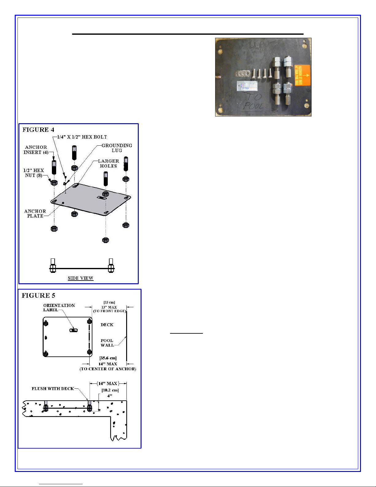
1) Locate the anchor late, four (4) anchor inserts with
nuts and mounting hardware). (Sold se arately from lift,
art number F-433PP4A - See icture).
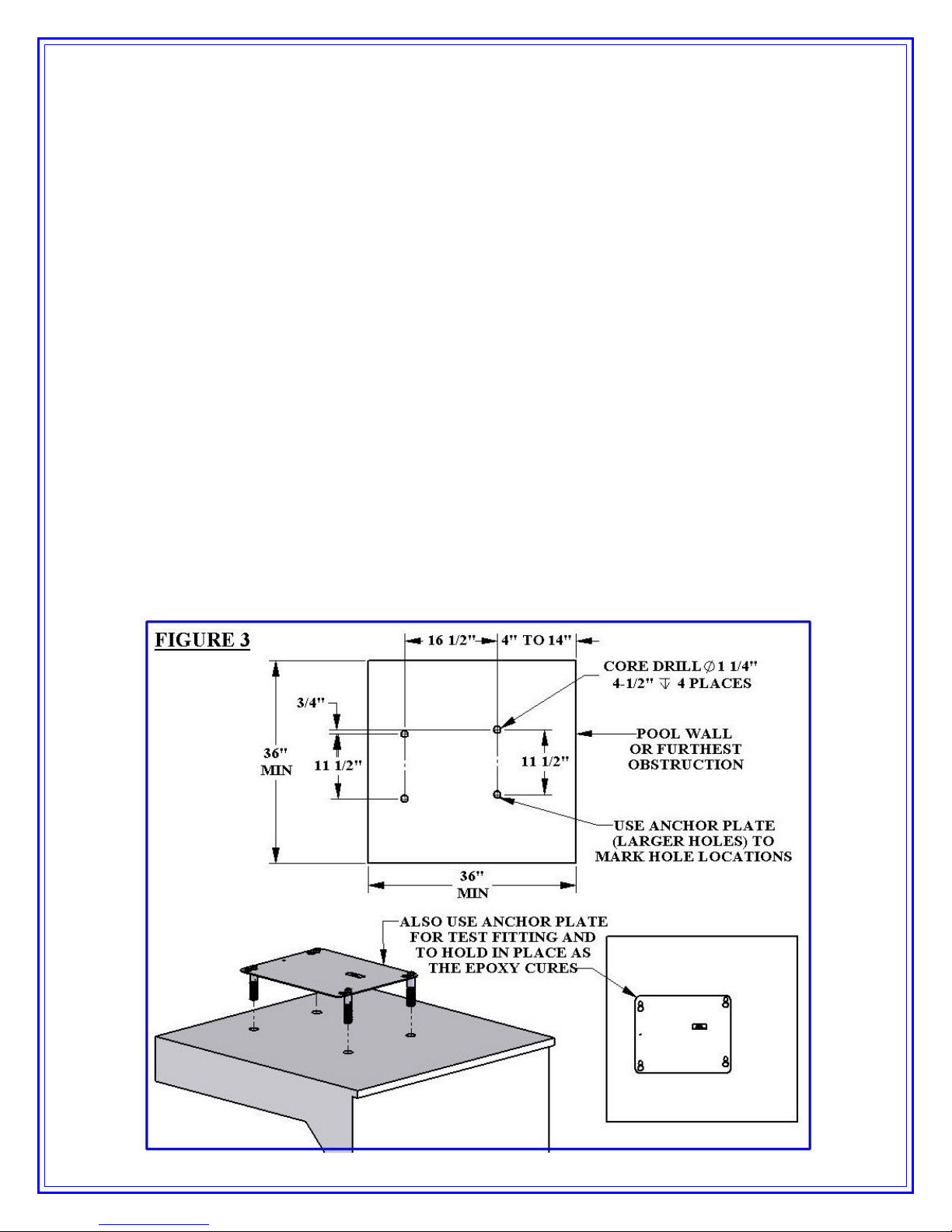
2) Mark out a section of the ool deck that you are
removing using a chalk line or straight edge and a
marker. You should lan on removing at least a Three
foot by three foot section.
3) Using the saw with the diamond blade, make your cuts
along the lines that you marked.
4) Using the sledge hammer, break u the concrete within
the area that you cut and remove the ieces.
5) After you have removed the ortion of the deck, verify
that your new deck will be able to be at least 6 inches
dee .
6) Remove ONE of the nuts from each of the anchor
inserts and lace the anchor inserts through the larger
holes in the anchor late. Thread the nut back on the
other side of the anchor insert so that the anchor late is
sandwiched between the nuts. (See diagram on left).
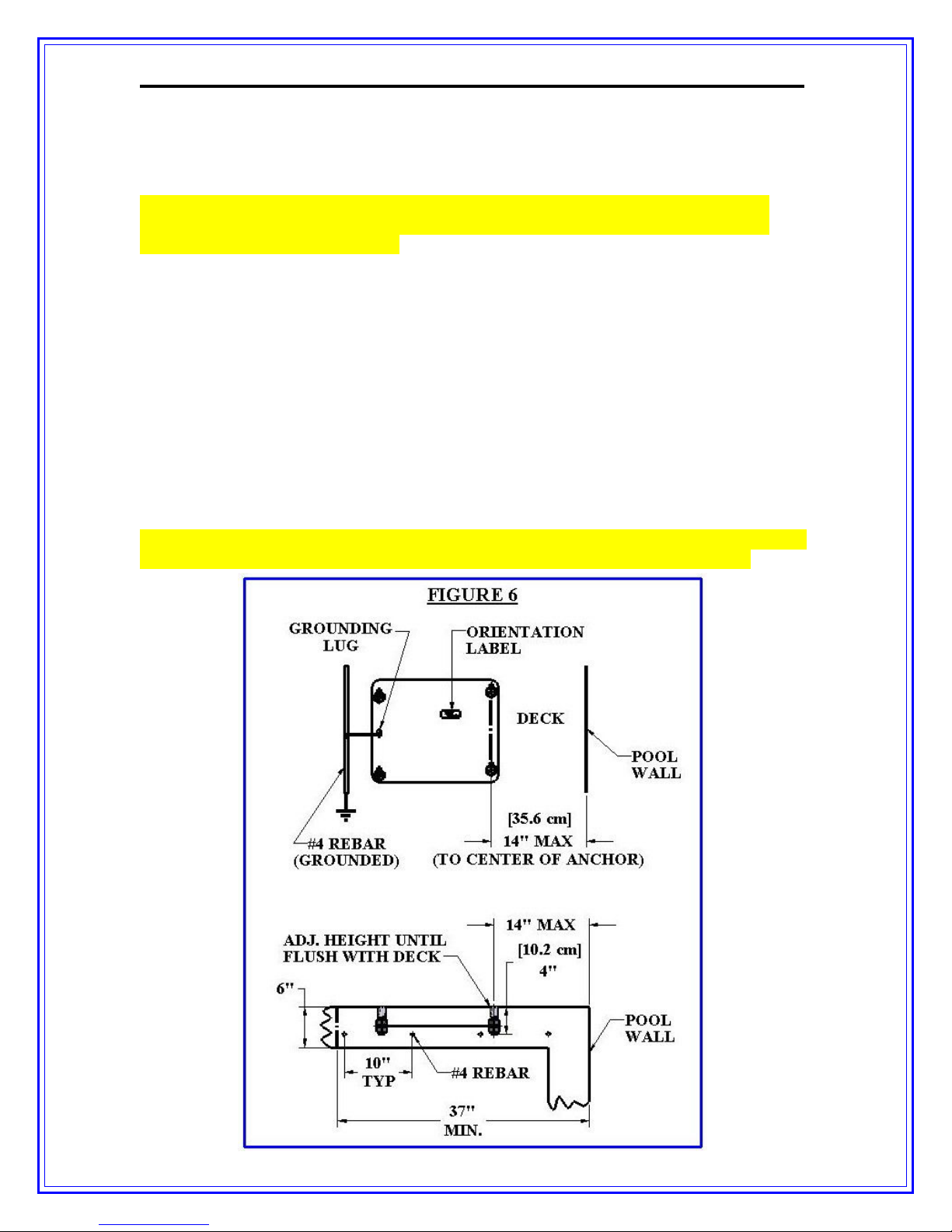
7) Install rebar in the o en area of the deck. Tie the rebar
into the existing deck if ossible.
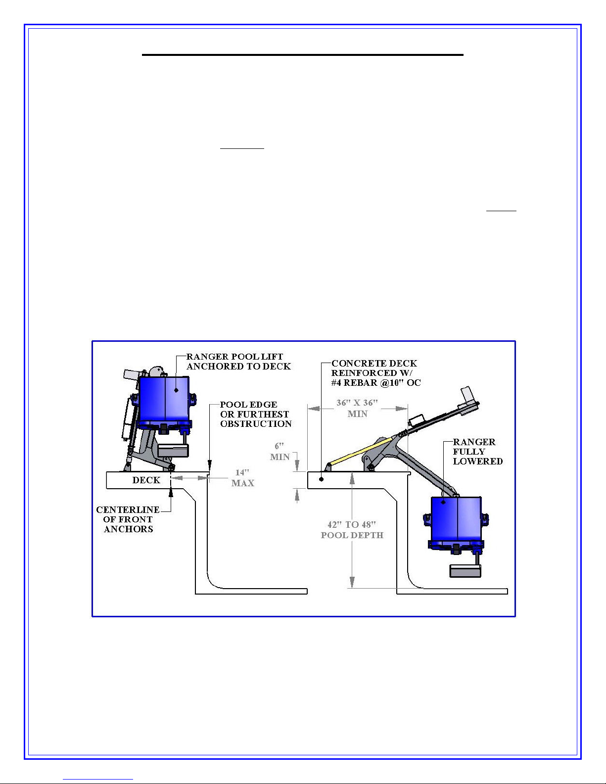
8) Set the anchor system in lace making sure that the
center line of the front anchor inserts are no more than
14 inches away from the ools edge.
9) Using the string line or a straight edge, make sure the
to of each anchor body is level and flush with the
FINIS ED deck surface. Each anchor body can be
adjusted individually by turning the nuts with a large
wrench.
10) Ground the anchor system using the grounding lug on
the anchor late according to your local code
requirements.
11) Pour your concrete and finish the ool deck surface.
12) Once the concrete has cured, install the lift by aligning
the holes in the lifts base with the anchors installed in
the deck. Secure the lift to the deck using the stainless
steel hardware that comes with it. (See drawing
below)
a. NOTE: Use Anti Seize on the hardware to
revent the hardware from seizing in the
anchor inserts.