AQUA JOY AUTO DELUXE User guide

Manufactured by:
JOY POOL SYSTEMS
ACN 141 035 172 ABN 66 141 035 172 Website: www.aquajoy.com.au
NORTH ROCKS NSW 2151 AUSTRALIA Ph: +61 2 9630 5011 Fax: +61 2 9683 4750
SALTWATER CHLORINATOR
OWNERS HANDBOOK
AUTO DELUXE & STANDARD

ii
DO NOT MOUNT THE POWER
PACK IN DIRECT SUNLIGHT.
DO NOT RUN POWER PACK WHEN
ADDING SALE, PUMP ONLY.
The pump must always be operating and water flowing through
the AQUAJOY cell when the AQUAJOY is switched on.
Please check that the pump is functioning correctly before
assuming that the AQUAJOY unit is not working.
Your AQUAJOY is fitted with a light which indicates when
the unit is switched on.
The AQUAJOY must be switched off at the switch marked
“CELL” when vacuuming to waste, backwashing (manually)
for long periods or when salt has been added to the pool.
POWER PACK CELL

iii
Important Safety Matters are indicated by
SAFETY PRECAUTIONS
SAFETY –FOR YOUR SAFETY AND THE SAFETY OF
OTHERS, BEFORE YOU OPERATE THIS
CHLORINATOR.
Do not operate the chlorinator unless you have read all WARNINGS
and INSTRUCTIONS and understand all safety / operating procedures
contained in this manual. Ensure that the chlorinator (Power Pack,
Plumbing and Cell) has been installed by competent personnel to the
instructions contained in this manual.
Power Pack is to be installed according to AS/NZ 3000-2000 and
located outside pool Zone 2 area.
Servicing should only be attempted by trained technicians. Dangerous
voltages are present inside the chlorinator enclosure. Untrained
personnel should not attempt to remove the cover of the power pack.
Return to supplier for repair.
For any unresolved problems, contact your dealer.
Keep this manual in a safe, convenient location and refer to it if any
doubt exists over operational or safety matters.

iv
SAFETY –TO PREVENT RISK OR INJURY TO
YOURSELF AND OTHERS, OBSERVE THE
FOLLOWING SAFETY INSTRUCTIONS:
Understand all safety and operational procedures contained in this
manual and check the condition of the chlorinator and cell before use.
Again, if in doubt, contact your dealer before proceeding.
Do not attempt to modify the chlorinator or installation in any way.
SAFETY –TO PREVENT RISK OR INJURY TO
YOURSELF AND OTHERS, OBSERVE THE
FOLLOWING SAFETY INSTRUCTIONS:
The chlorinator should not be operated by personnel (eg. operating front
panel switches, adjusting time clock, safety cutout, cleaning cells etc.)
when the surrounding area is damp. In addition, personnel should not
operate the unit with bare feet or wet hands. This will minimise the risk
of electrocution in the event of a fault developing either in the
chlorinator or the electric power wiring to the unit.
SAFETY –CELL CLEANING USES HYDROCHLORIC
ACID. CARE IS REQUIRED.
Cell cleaning may require the use of hydrochloric acid which is a highly
corrosive chemical that needs to be handled with extreme care.
Personnel performing cleaning should be equipped with safety goggles
and acid resistant gloves as a minimum.

v
Any spills should be immediately flushed with water. When diluting the
acid ALWAYS ADD ACID TO WATER … NEVER THE REVERSE.
Take care when immersing the cell in the diluted acid solution to ensure
that no acid splashes or spills occur. When finished, wash gloves and
used containers in water.
Please note that the edges of the cell electrodes can be extremely sharp.
Avoid contact when cleaning as lacerations may occur.
SAFETY –IF IN ANY DOUBT ABOUT THE SAFETY OF
THE UNIT OR IF THE UNIT MALFUNCTIONS, ADOPT
THE FOLLOWING SAFETY INSTRUCTIONS:
Turn off the power to the unit at the power point. Disconnect the power
cord and call for service.
SAFETY –STORAGE OF CHEMICALS:
Never store chlorine and hydrochloric acid is the same area. They are
both very active chemicals and can react, if accidentally missed, with
explosive results.
SAFETY –ASPECTS TO BE CONSIDERED FOR
SERVICING:
Servicing should only be attempted by trained technicians. Dangerous
voltages are present inside the chlorinator enclosure. Untrained
personnel should not attempt to remove the cover of the power pack.

vi
Servicing should be carried out with the power switch off and the
chlorinator disconnected from the power point. Where is it absolutely
necessary to power the unit for service then it shall be powered from the
unearthed secondary of a safety isolation transformer or by means of an
approved earth leakage detection unit.
The chlorinator is a prescribed item under NSW law and cannot be
modified in any way.
As part of servicing the following safety checks need to be performed on
the chlorinator:
•The interior of the unit has not been modified or tampered with
in any way.
•There is adequate separation between mains and extra low
voltage parts.
•All insulating panels are in place and terminal connections are
tight.
•Earth pin of power cord to all external metal parts of the
chlorinator to have a resistance value not exceeding 0.1ohm.
•Megger power cord active and neutral at 500 V D.C. to all
external metal work and output cell terminals in turn.
Resistance value not to be less than 2 meg ohm.
•Visually ensure that all parts of the unit are in good condition.
Insulation on power cords is in good condition and any
corrosion on the pins of the power cord plug to be rectified.
Place a sticker on the underside of the unit identifying the Company that
carried out the service, date of service, safety check carried out and the
signature of the service technician that carried out the work.

vii
CONTENTS
INTRODUCTION .............................................................................. 1
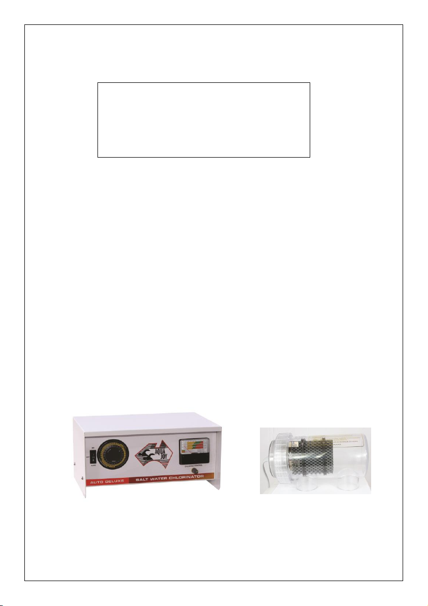
“Aquajoy” Salt Water Chlorinator Models ....................................... 1
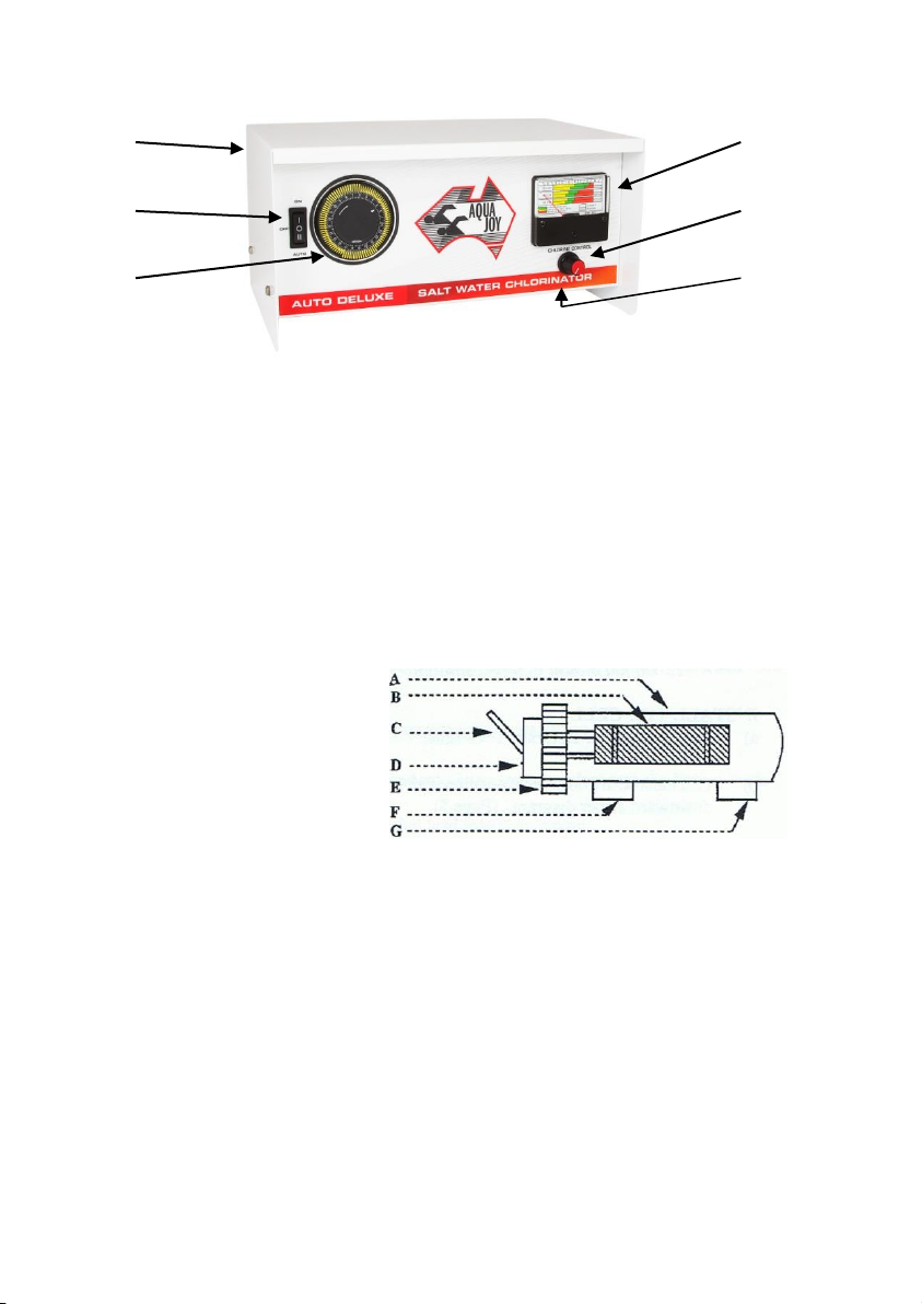
Identification Details & Explanations ............................................... 2
INSTALLATION................................................................................ 3
Check List Before Turning On.......................................................... 5
Installation Diagram ........................................................................ 5
OPERATION –START UP PROCEDURE ....................................... 5
CHLORINE PRODUCTION TEST ................................................... 6
GENERAL INFORMATION ON WATER CARE............................ 7
Filtration .......................................................................................... 7
Chlorination..................................................................................... 7
pH.................................................................................................... 7
Conclusions ..................................................................................... 8
MAINTENANCE ............................................................................... 8
Cleaning of the Cell.......................................................................... 8
Adding Salt ...................................................................................... 9
Power Pack Maintenance ................................................................. 9
SALT REQUIREMENT CHART ......................................................10
Understanding the Chlorine Monitor...............................................11
Setting the Clock .............................................................................12
Checklist when Problems Occur ......................................................13
Service –Check List ........................................................................14
Cell & Power Pack Maintenance .....................................................15
WARRANTY ....................................................................................16

1
INTRODUCTION
Congratulations on your choice of “Aquajoy” Salt Water Chlorinator.
Check your Model and follow appropriate instructions. Care and only
top-quality components have been used to ensure you, the Pool Owner,
may enjoy the benefits of your chlorinator. No commodity can operate
successfully without understanding. This Handbook has been compiled
to assist you on Basic Pool Care.
“AQUAJOY” SALT WATER CHLORINATOR MODELS
1. STANDARD
2. AUTO DELUXE Time Clock
AQUAJOY STANDARD
Ideal for established and new pools,
where a time clock is already fitted.
AQUAJOY AUTODELUXE T.C.
Similar to the Standard but fitted with a
time clock for automatic filter operation.
AQUAJOY CELL
This unique design is engineered for
maximum chlorine output. It features the
latest clear (see through) material and is
available in three sizes.
CELL COMBINATIONS
60cm
60,000 litres
90cm
90,000 litres
150cm
150,000 litres

2
IDENTIFICATION DETAILS & EXPLANATIONS
A B
C D
E F
A. Power Pack
B. Chlorine Monitor –see page 11.
C. On / Off / Auto switch. Up “ON”, in the middle “AUTO” and Down is
“OFF” In the “On” position pump will run continuously by over-riding the
time clock –normal position “AUTO” when in time clock mode.
D. Chlorine production dial. Anticlockwise to reduce, clockwise to increase.
E. Time clock –see page 12.
F. 3A Circuit Breaker.
A. Cell Casing
B. Cell Electrodes
C. Cell Lead to Power Pack
D. Electrode Holder
E. Screw Cap –unscrew anti-clockwise
F. Outlet or Inlet Port *
G. Inlet or Outlet Port *
* Install either way for ease of removal when cleaning.

3
INSTALLATION
These instructions should be read and understood completely before
starting installation. Correct installation is mandatory for correct and
safe operation.
1. POOL WATER PREPARATION
a) Measure the pool size in litres to determine salt requirements.
b) Refer to salt requirement chart. (page 10). Add 4kg of refined salt
per 1000 litres of water in shallow end of pool.
c) Connect up vacuum hose and place vacuum head close to salt.
This will cause salt to dissolve quicker.
d) BEFORE CHLORINATOR IS TURNED ON the salt must be
dissolved completely (24 hours in summer, 72 hours in winter).
2. MOUNT THE POWER PACK
a) Screw mounting bracket to wall or post with slots facing upwards
within 1.5 metres of the power outlet and within 1.5 metres of the
Filter Return to Pool Line.
b) Place back of Power Pack to mounting bracket and slot into place.
Note: Do not mount in direct sunlight.
3. INSTALL THE CELL
a) Determine Filter Return to Pool Line.
b) Cell must be in a horizontal position with inlet and outlet sockets
facing downward as per diagram (page 5).
c) Cell must be installed before all breakout lines such as dual outlets,
Spa lines.
d) Cell must be installed after the heater (where fitted) and Solar
systems (see Diagram Page 5). Pool cleaner pump motors which
draw water from the return to pool line should be fitted after the
Cell for correct pool chlorination.

4
e) CAUTION. It is very important that no gas generated from the
Cell can find its way back into the Filter Pump, Heater, Solar
Systems or Spa Blowers.
f) When position to install Cell has been decided, turn off Filter
AND CLOSE OFF VALVES.
g) If Return to Pool Line is 40mm pipe, use 50-40mm reducers
provided. If50mm pipe, glue pipe/fittings direct to inlet and outlet
ports.
4. POWER PACK / CELL CONNECTION
a) The Cell is supplied already connected to the Terminal Box under
the Power Pack.
b) If it is necessary to disconnect the cell lead, re-assemble as follows:
i. Attach Blue wire of cell lead to Blue wire of Terminal
Box.
ii. Attach Brown wire of Cell lead to Brown wire of
Terminal Box.
iii. Attach small Black Sensor lead wire to centre terminal.
NOTE: The unit cannot function if wired incorrectly and will void
warranty.
5. PUMP / CHLORINATOR LEAD CONNECTION
a) Insert Pump plug lead into 3 pin socket underneath the Power Pack.
b) Insert Chlorinator plug lead into power point.
NOTE: Do not plug more than 1 pump into socket underneath
Power Pack.

5
CHECK LIST BEFORE TURNING ON
1. Pool Salt all dissolved.
2. Glue is set (allow 24 hours).
3. Valves re-opened.
INSTALLATION DIAGRAM
NOTE: WATER MAY FLOW EITHER WAY
THROUGH INLET / OUTLET PORTS ON
CELL. (CELL MAY BE REVERSED AS
SHOWN IN DIAGRAM).
GAS AND ELECTRIC HEATERS REQUIRE
CELL INSTALLED MINIMUM OF 1 METRE
FROM HEATER OUTLET.
OPERATION –START UP PROCEDURE

6
a) Time Cell Switch on “ON” position.
b) Set Chlorine Production Switch to maximum on position. Turn on
Mains / Power supply.
c) Filter and Chlorinator are now running.
d) Check Clock and running times –see Page 12.
e) Set Chlorine Monitor needle is in normal operation sector.
CHLORINE PRODUCTION TEST
1. Turn on Filter and Chlorinator.
2. Place thumb over chlorine test vial and place next to return to pool
outlet.
3. Allow water to fill vial and replace thumb over vial before return to
surface.
4. Add the chlorine test tablet and note the reading.
5. The reading should be greater than 1 ppm.
NOTE: ENSURE CHLORINE PRODUCTION SWITCH IS ON
HIGH SETTING DURING TEST. HIGH SETTING
SHOULD BE USED DURING SUMMER AND WARMER
WATER CONDITIONS.

7
GENERAL INFORMATION ON WATER CARE
A basic knowledge of pool care fundamentals will allow some insight into
the function of the various pieces of equipment and chemicals used in and
around your pool.
The three fundamental requirements in maintaining a pool or any body of
water are:
1. Adequate filtration
2. Sufficient Chlorination
3. Proper pH control.
FILTRATION
It is necessary to pass water through a filter to remove the debris.
Typically, a powerful pool pump (with normal filter pressures) will pump
approx. 10,000 litres an hour. Normal pool practice demands all the pool
water pass through the filter at least one and one-half times (1½ times) per
day and this is normally achieved in a six to ten hours filtration cycle to
remove 60% of the debris in the water. The longer the filtration cycle the
better will be the clarity and polish in the water. However excessive
filtration causes excessive electricity bills and wear and tear on
equipment.
CHLORINATION
Chlorine is required to react with the debris, removing stains by oxidation
and to sterilise the water of harmful bacteria. Chlorine residual or reserve
is required for bather loading. Normally if 1 ppm of chlorine is
introduced then one and one half (1½) filtration cycles of the pool water
will leave the water in a clean, clear condition. Clear water is achieved
only with filtration and chlorination. Longer filtration cycles can reduce
the chlorine demand and conversely more chlorine can reduce the
filtration requirements.
PH
The acid / alkaline balance of water is measured using the pH scale. pH
14 is alkaline, 0 is acid and 7 is neutral. pH control is the third essential
to pool care. Within the pH range of 7.0 to 7.8 chlorine will work as a
bleach and steriliser and the precipitates formed will be at their maximum
size. A pH above 8.0 is too alkaline and will cause skin rashes and below
7.0 will sting sensitive tissues due to acidity. The ideal pH is in the range
of 7.0 to 7.4.

8
CONCLUSIONS
It follows then that your pool must have an adequate circulation,
chlorination and filtration system and the pH should be in the correct
range.
The use of Pool Stabiliser (iso-cyanuric acid) in hot weather will help
keep a reserve of chlorine in the pool.
MAINTENANCE
CLEANING OF THE CELL
Check at weekly intervals to determine amount of deposit (calcium etc.)
on the electrodes. A heavy build-up may interfere with the flow of
electrical current and subsequently the production of Chlorine. It may
also damage the anode electrodes and cause damage beyond repair.
1. Switch off the filtration and Chlorinator and close valves.
2. Unscrew cap in an anti-clockwise direction.
3. Remove electrode holder and soak electrodes in very hot water and
detergent.
4. If ineffective, we recommend you immerse the Cell in Lo-Chlor “Cell
Clean”. Soak for 30 minutes or until clean and rinse in clean water.
5. Insert electrode holder into Cell body, ensuring locating lug is at top
of cell.
6. Lubricate “O” ring using only silicon grease for complete sealing.
7. Open valves, turn on filtration and chlorinator.
8. Check Chlorine monitor reading.

9
ADDING SALT
Use only refined salt in your pool. The chlorinator is designed to run in
at least 4,000 ppm of Salt –lower than 4,000 ppm will cause problems in
your pool and may void electrodes warranty.
1. If after cleaning Cell the Chlorine Monitor is not operating in the
normal position, add 1 x 25kg bag of salt into pool at shallow end.
Ensure Chlorine production dial is turned down.
2. Allow salt to dissolve and increase Chlorine output. Inspect Chlorine
Monitor. If not in normal sector, repeat as above until correct
reading is achieved.
POWER PACK MAINTENANCE
Regular maintenance of the Power Pack should be confined to keeping it
in a clean, dry position away from sunlight. The brass screws which
connect the cell leads to the Power Pack should be checked and tightened
about every three months.

10
SALT REQUIREMENT CHART
Eg: To achieve 4,000 parts per million salt in 60,000 litres of pool water,
add 240kg salt.
Parts per million Salt
Litres of
Water
500
1000
1500
2000
2500
3000
3500
4000
4500
5000
5500
5000
2.5
5
7.5
10
12.5
15
17.5
20
22.5
25
27.5
10,000
5
10
15
20
25
30
35
40
45
50
55
15,000
7.5
15
22.5
30
37.5
45
52.5
60
67.5
75
82.5
20,000
10
20
30
40
50
60
70
80
90
100
110
25,000
12.5
25
37.5
50
62.5
75
87.5
100
112.5
125
137.5
30,000
15
30
45
60
75
90
105
120
135
150
165
40,000
20
40
60
80
100
120
140
160
180
200
220
45,000
22.5
45
67.5
90
112.5
135
157.5
180
202.5
225
247.5
50,000
25
50
75
100
125
150
175
200
225
250
275
*60,000
30
60
90
120
150
180
210
240
270
300
330
65,000
32.5
65
97.5
130
162.5
195
227.5
260
292.5
325
357.5
70,000
35
70
105
140
175
210
245
280
315
350
385
75,000
37.5
75
112.5
150
187.5
225
262.5
300
337.5
375
412.5
80,000
40
80
120
160
200
240
280
320
360
400
460
Kilograms of Salt
* Example for 60,000 Litre Pool

11
UNDERSTANDING THE CHLORINE MONITOR
The chlorine monitor presents a
visual indication of the chlorination
process of your Aquajoy. It does
NOT relate to pH control but
supersedes the need for messy
chemical analysis and test kits; it is a
passive INDICATOR and slow to
change.
Allow at least 7 DAYS on your pumping programme for the pool and cell
to “settle in” before placing reliance on the monitor as certain slow
chemical changes take place in the initial salt charging.
The capacity or output of your Aquajoy chlorinator has been designed to
suit the capacity of your pool, i.e. 60-90-150CM = cubic metres. This
capacity is shown on the label fixed to the front of the chlorine monitor
and is to be the reference in relation to ONE of the 3 levels shown on the
scale.
Each level is divided into SUMMER and WINTER sectors and each
sector has 3 coloured areas –YELLOW, GREEN, ORANGE (see colour
coding in lower left hand corner) and the monitor needle position will
vary according to the condition of your pool and cell, ie salinity or salt
content, pool water temperature and the cleanliness condition of the cell
which is an electrolytic generator of chlorine (refer page 8).
The letters A to H at the top of the scale of the monitor are a further
reference relating to the indicator needle position within a coloured
sector.
A summary of the above information will be indicated as in the following:
YELLOW
1.
Calcium deposit on cell electrodes (page 8) and or
2.
Salt level has lowered (page 0) and or
3.
Very low pool temperatures.
GREEN
Normal
ORANGE
High output from Aquajoy due to
a) Higher water temperatures (heated pool) and or
b) Salt level over 4,000 ppm minimum.
NOTE: THE CHLORINE MONITOR IS FACTORY CALIBRATED AT 24°
CELCIUS WATER TEMPERATURE. HIGHER TEMPERATURES
WILL INCREASE NEEDLE SETTING INTO ORANGE SECTOR.

12
Maintenance Procedure
If the Monitor needle is in the YELLOW sector and NOT the normal
(GREEN) sector, the following procedure should be carried out. Ensure
Chlorine Production Switch is on high setting.
1) Check cell for calcium deposit (clean if necessary). SUMMER
2) Check water temperature, weather, summer/winter? WINTER
3) Extra salt to be added (1 x 25kg bag) at a time. Allow to fully
dissolve until needle on monitor returns to NORMAL (GREEN
sector) position.
CAUTION: Each of the maintenance procedures must be carried out in
order of preference ie. 1 to 3.
SETTING THE CLOCK
This clock controls the Pump / Filter which is switched ON and OFF by
the position of the white tappets. The dial is for 24 hours and each tappet
represents 15 minutes. The correct time is set at the white indicator
(arrow) situated at “2.0 O’clock” on the black face.
To set the Time Clock, push white tappets outwards to the perimeter of
the Clock face until they click into place. We suggest you run your Pump
/ Filter and Chlorinator for a minimum of 6 hours per day in the summer
ie 6.00 am to 9.00 am (12 tappets out) for 3 hours running in the morning.
For afternoon running –5.00 pm to 8.00 pm. Push out 12 tappets from
1700 –2000 hours.
The Pump Switch over-rides the Time Clock to enable the Pump / Filter
and Chlorinator to be operated at times other than the dial setting.
Should the power supply be interrupted the clock should be reset to the
correct time.
WARNING: Turn the clock dial only in the direction of arrow, ie
clockwise, or damage will result.

13
CHECKLIST WHEN PROBLEMS OCCUR
Problem
Possible Cause
Chlorine Residual
Insufficient running times
Low or Nil
pH too high or low
Strong sunlight and low conditioner levels
Poor circulation
Heavy bather loading
Low chlorine production
Chlorine Production
Low salt levels
Air in cell casing
Low or Nil
Scale build up on the cell
Faulty circulation
Algaecide addition within the last 2 to 3 weeks
Cell leads incorrectly connected
Debris levels in the pool too high
Cell too old and worn out.
Chlorine Levels High in mornings and low
at night
Heavy bather loadings
Extreme sunlight conditions
Insufficient pool conditioner levels
pH alters rapidly and easily
A low total alkalinity level in Marblesheen, pebble or tiled
pools.
Contamination with debris especially urine could be another
cause.
Poor circulation
Dirty and clogged filter
Hair and link baskets full or leaves at the skimmer boxes or
pump
Faulty pump
Water levels is low or cell is clogged with scale
Short intervals between backwashes
Ineffective backwashing
Body fat or oil build up on pads. With Diatomaceous earth
filters the cause may be insufficient diatomaceous earth over
the pads.
Cloudy water
Insufficient filtration times
Holes in the filter pads
High pH
Pool walls need brushing
Main drain not working
Algaecide’s have been added in the last few weeks
Bather load too great for filtration and chlorine times.
Low salt level
The results of splash out by bathers
Heavy overflow from rain or accidental filling of the pool
Topping up because of pool leaks or from excessive
backwashing
Appearance of Stains
Low chlorine levels
High pH levels
Poor circulation
Infrequent brushing of the pool walls
Incorrect total alkalinity
Algae Formation and High Chlorine Levels
The pH is over 7.4
The pool conditioner level is too high
Frequent Cell cleaning
Hard bore water being used
Incorrect total alkalinity levels in Marblesheen, pebble, tiled or
heated pools
pH levels may also be too high
Prior to the CHLORINATOR and currently, are you still
adding powdered chlorine?
This manual suits for next models
4
Table of contents