DSP-599zx Audio Noise Reduction Filter
ix
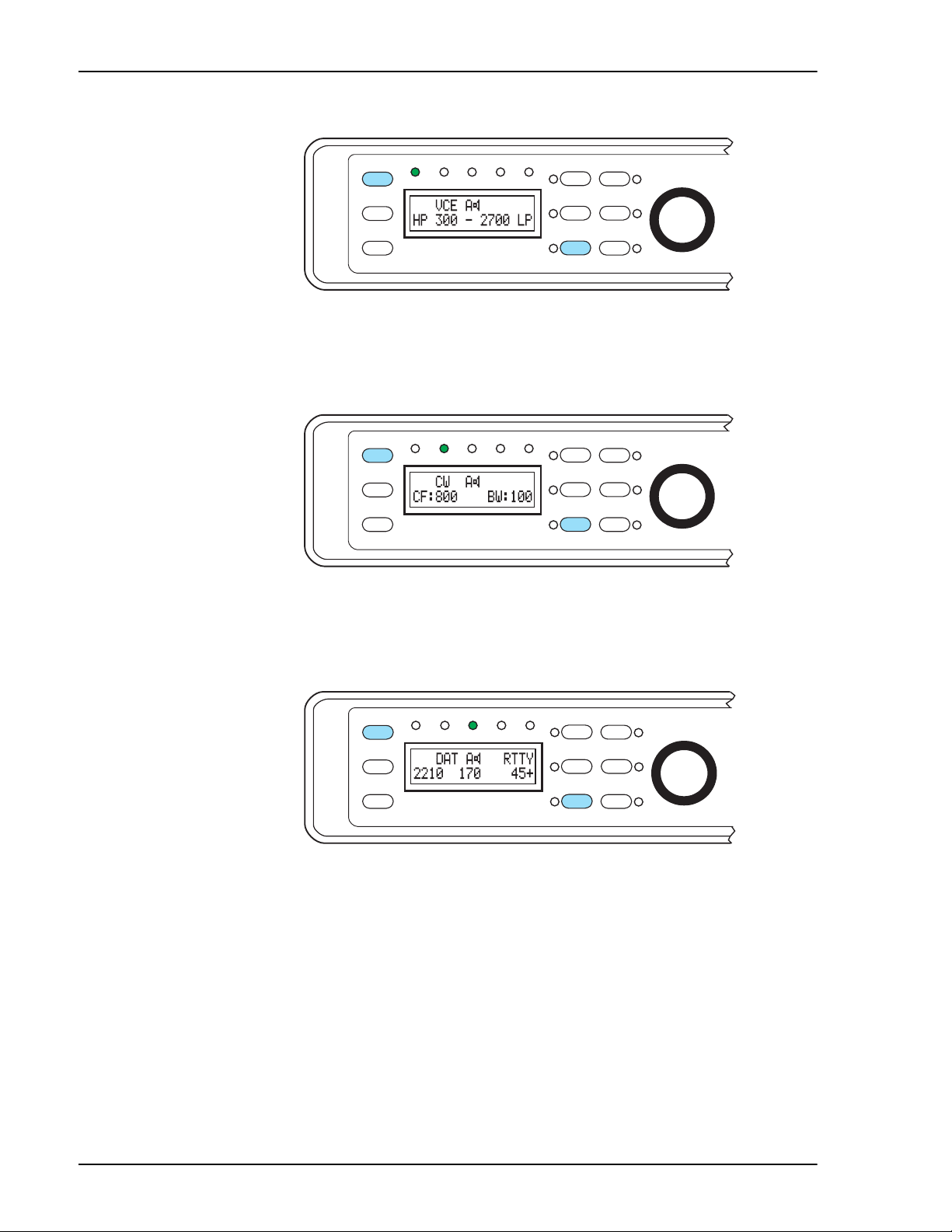
Voice Mode 4-1
Operation .....................................................................................................................4-1
High Pass/Low Pass Filters ..................................................................................... 4-1
Noise Reduction .......................................................................................................4-2
AM Line Noise ........................................................................................................4-3
Heterodyne Elimination/Notch Filters .....................................................................4-4
Automatic Notch Filter .........................................................................................4-4
Manual Notch Filter ..............................................................................................4-5
Voice Bypass ...........................................................................................................4-6
Setup - Voice ................................................................................................................4-6
AM Line Noise ........................................................................................................4-7
Exit Setup .................................................................................................................4-7
CW Mode 5-1
Operation .....................................................................................................................5-1
Bandpass Filters .......................................................................................................5-1
Noise Reduction .......................................................................................................5-2
Manual Notch Filter .................................................................................................5-2
CW Marker Tone..................................................................................................... 5-3
CW Tone Pitch Shift ................................................................................................5-3
CW Bypass Mode ....................................................................................................5-4
Setup - CW................................................................................................................... 5-5
Marker Tone Level ..................................................................................................5-5
Exit Setup .................................................................................................................5-5
Data Mode 6-1
Introduction .................................................................................................................6-1
Operations Common To All Data Types ..................................................................6-1
Basic Data Mode Operation .....................................................................................6-1
Data Settings Display ..............................................................................................6-2
Data Tuning Function ..............................................................................................6-2
Random Noise Reduction........................................................................................ 6-3
Data Bypass Mode ...................................................................................................6-3
Data Filter Mode .........................................................................................................6-4
RTTY, AMTOR, SITOR, PacTOR, G-TOR ...........................................................6-4
HF Packet .................................................................................................................6-5
CLOVER .................................................................................................................6-5
SSTV and WeFAX ..................................................................................................6-5
RTTY FSK Test Signals ..........................................................................................6-5
RTTY Modem Operation ...........................................................................................6-6
RTTY Remodulator Operation ..................................................................................6-7
Data Operating Hints ................................................................................................. 6-8
Data Primer ..............................................................................................................6-8
Frequency shift ......................................................................................................6-8
Center Frequency ..................................................................................................6-8
Baud Rate ..............................................................................................................6-9
QRM Operating Hint............................................................................................... 6-9
Mark Space Frequencies ..........................................................................................6-9
Setup - Data Mode .................................................................................................... 6-10
Speaker Mute/Bypass ............................................................................................ 6-10
Modem Assignment ...............................................................................................6-11
FSK Mark Control .................................................................................................6-11