Aqua Medic cool control User manual

1
cool control
D Bedienungsanleitung
Vor Gebrauch aufmerksam lesen! S. 2-3
ENG Operation manual
Please read the manual carefully before use! P. 4-5
F Mode d’emploi
Veuillez lire soigneusement les instructions d’avant utilisation ! P. 6-7
NL Gebruiksaanwijzing
Lees de handleiding voor gebruik zorgvuldig door! P. 8-9
ES Manual de instrucciones
Por favor lea el manual cuidadosamente! P. 10-11
IT Manuale Operativo
Leggere il manuale attentamente in modo! P. 12-13
PL Instrukcja użytkowania
Prosimy uwaznie przeczytać instrukcje! S. 14-15
RUS Инструкция по эксплуатации
Пожалуйста, внимательно ознакомьтесь с инструкцией
по эксплуатации! C. 16-17
_________________________________________________________________________
Declaration of Conformity P. 18
Product Info AB Aqua Medic GmbH
Gewerbepark 24, 49143 Bissendorf, Germany
_________________________________________________________________________________

2
Bedienungsanleitung D
Digitales Temperatur-Mess- und Regelgerät zur Steuerung von 12/24 V-Lüftern
Mit dem Kauf dieses digitalen Temperatur Mess- und Regelgeräts haben Sie sich für ein Qualitätsinstrument
entschieden. Es ist speziell für den aquaristischen Gebrauch entwickelt worden. Mit diesem Gerät sind Sie in der
Lage, die Temperatur Ihres Aquarienwassers kontinuierlich zu messen und zu regeln.
1. Lieferumfang
Temperatur-Controller cool control mit Touch Display zur Steuerung von 12 oder 24 Volt DC Lüftern mit
Hohlstecker (5,5 mm x 2,1 mm). Der Aqua Medic Temperatur-Controller cool control ist serienmäßig mit einem
meerwasserfesten Temperatursensor ausgestattet und anschlussfertig. Ohne Netzteil und Lüfter.
2. Sicherheitshinweise
- Bei Arbeiten im Aquarium grundsätzlich alle Geräte vom Stromnetz trennen, bevor man die Hände ins Wasser
taucht. Alle Geräte über eine Fehlerstrom-Schutzeinrichtung mit einem Differenzstrom von maximal 30 mA
mit dem Stromnetz verbinden.
- Ausschließlich für den Gebrauch in geschlossenen Räumen geeignet.
- Controller vor Feuchtigkeit, Spritz- und Kondenswasser schützen.
- Nicht als Spielzeug für Kinder geeignet.
3. Lüfter
Es kann ein 12 oder 24 V DC Lüfter mit Hohlstecker (5,5 mm x 2,1 mm) angeschlossen werden. Das Netzteil des
Lüfters wird als Stromversorgung an den entsprechenden Anschluss des Controllers (Abb. 1, Nr. 5)
angeschlossen, der Lüfter an den Stromausgang des Controllers (Abb. 1, Nr. 6).
4. Beschreibung der Frontplatte
Abb. 1: cool control
1. Lüfterleistung
2. Sollwert + Set
3. Istwert
4. Temperatursensor
5. Stromversorgung 12 oder 24 V DC. Buchse für Hohlstecker (5,5 mm x 2,1 mm)
6. Anschluss für Lüfter mit Hohlstecker (5,5 mm x 2,1 mm)
7. Pfeiltasten zum Verstellen der Parameter
8. Pfeiltasten zum Verstellen der Parameter
9. Ein-/Aus-Taste

3
5. Technische Daten
Anzeige: 0 – 36 °C
Regelbereich: -20 - 50 °C
Auflösung: 0,1 °C
Regelgenauigkeit: 0,5 °C
Belastbarkeit des Kontaktes: max. 65 W
Luftfeuchtigkeit: unter 80%
Stromversorgung: 12 oder 24 V DC
Abmessungen: 120 x 62 x 28 mm
6. Inbetriebnahme
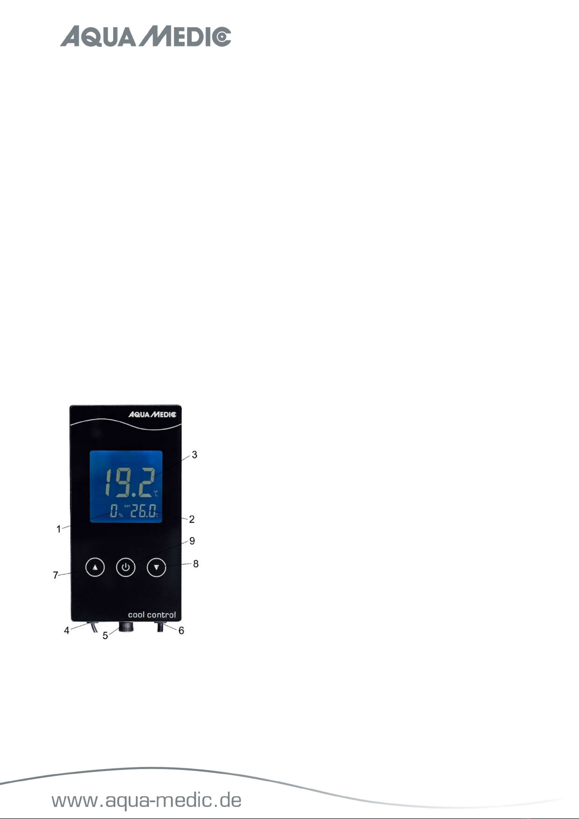
A) Einstellung EIN/AUS (Abb. 1, Nr. 9)
Im ausgeschalteten Zustand kurz drücken, um einzuschalten; im eingeschalteten Zustand kurz drücken, um
auszuschalten.
B) Einstellung der Abschalttemperatur
Drücken Sie im laufenden Betrieb kurz die Taste ▼ oder ▲, auf dem Display beginnt SET vor dem Sollwert (Abb.
1, Nr. 2) zu blinken. Drücken Sie dann die Taste ▼ oder ▲, um die Abschalttemperatur einzustellen. Nachdem
dieser Vorgang abgeschlossen ist, wird der Sollwert binnen drei Sekunden automatisch gespeichert.
C) Einstellung der maximalen Lüfterleistung
Halten Sie im laufenden Betrieb die Taste ▲ drei Sekunden lang gedrückt, auf dem Display erscheint MAX.
Drücken Sie dann die Taste ▼ oder ▲, um die gewünschte Lüfterleistung (40-99%) einzustellen. Der eingestellte
Wert wird automatisch innerhalb von drei Sekunden gespeichert. Reicht der eingestellte Wert nicht aus, um die
gewünschte Abkühlung zu erreichen, muss die Leistung, sofern möglich, erhöht werden.
D) Ausgabesteuerung
Ist die angezeigte Temperatur 0,5 °C höher als der Sollwert, erscheint ein Lüftersymbol und der angeschlossene
Lüfter beginnt zu arbeiten. Bei Erreichen des Sollwertes stellt sich der Lüfter ab, das Lüftersymbol verschwindet.
7. Alarm
A) Hoch- bzw. Niedertemperatur-Alarm
Die Anzeigetemperatur beträgt mehr als 50 °C, der Lüfter blinkt, HHH wird angezeigt und es ertönt ein Alarmton.
Drücken Sie eine beliebige Taste, um den Alarmton abzustellen. Beträgt die Anzeigetemperatur weniger als -20
°C, erscheint in der Anzeige LLL, es ertönt ein Alarmton. Drücken Sie eine beliebige Taste, um den Alarmton
abzustellen. Wenn die angezeigte Temperatur in den Bereich von -20 ~ 50 °C zurückkehrt, verschwindet der
Alarmcode.
B) Fühlerfehler-Alarm
Wenn der Sensor einen Kurzschluss oder einen offenen Stromkreisfehler hat, funktioniert der angeschlossene
Lüfter nicht. Anstelle der Ist-Temperatur wird EEE angezeigt, es ertönt ein Alarmton. Der Alarm kann nur durch
Ausschalten des Gerätes abgestellt werden.
8. Garantiebedingungen
AB Aqua Medic GmbH gewährt dem Erstkäufer eine 24-monatige Garantie ab Kaufdatum auf alle Material-und
Verarbeitungsfehler des Gerätes. Im Übrigen stehen dem Verbraucher die gesetzlichen Rechte zu; diese werden
durch die Garantie nicht eingeschränkt. Als Garantienachweis gilt der Original-Kaufbeleg. Während der
Garantiezeit werden wir das Produkt kostenlos durch den Einbau neuer oder erneuerter Teile instand setzen. Die
Garantie deckt ausschließlich Material-und Verarbeitungsfehler, die bei bestimmungsgemäßem Gebrauch
auftreten. Sie gilt nicht bei Schäden durch Transporte, unsachgemäße Behandlung, falschen Einbau,
Fahrlässigkeit oder Eingriffen durch Veränderungen, die von nicht autorisierter Stelle vorgenommen wurden. Im
Fall, dass während oder nach Ablauf der Garantiezeit Probleme mit dem Gerät auftreten, wenden Sie
sich bitte an den Fachhändler. Alle weiteren Schritte werden zwischen dem Fachhändler und AB Aqua
Medic geklärt. Alle Reklamationen & Retouren, die nicht über den Fachhandel zu uns eingesandt
werden, können nicht bearbeitet werden. AB Aqua Medic haftet nicht für Folgeschäden, die durch den
Gebrauch des Gerätes entstehen.
AB Aqua Medic GmbH - Gewerbepark 24 - 49143 Bissendorf/Germany
- Technische Änderungen vorbehalten – 03/2021/v5

4
Operation Manual ENG
Digital temperature measuring and regulating unit for controlling 12/24 V fans
With the purchase of this digital measuring and regulating unit, you have selected a top quality product. It has
been specifically designed for aquaristic purposes. With this unit, you can continuously measure and control the
temperature of the water in your aquarium.
1. Included in shipment
Temperature controller cool control with touch display for controlling 12 or 24 volt DC fans with barrel connector
(5.5 mm x 2.1 mm). The Aqua Medic temperature controller cool control is equipped with a saltwater-proof
temperature sensor as standard and is ready for connection. Without power supply and fan.
2. Safety instructions
- When working in the aquarium, always disconnect all units from the power supply system before putting your
hands into the water. Connect all units to the mains via a residual current device with a maximum residual
current of 30 mA.
- Suitable for indoor use only.
- Protect the power supply and controller from moisture, splash and condensate.
- Not suitable as a toy for children.
3. Fan
A 12 or 24 V DC fan with a barrel connector (5.5 mm x 2.1 mm) can be connected. The power pack of the fan is
connected to the corresponding connection on the controller (Fig. 1, No. 5) as a power supply, the fan is connected
to the power output of the controller (Fig. 1, No. 6).
4. Description of the front panel
Fig. 1: cool control
1. Fan power
2. Nominal value + set
3. Actual value
4. Temperature sensor
5. Power supply 12 or 24 V DC. Socket for barrel connector (5.5 mm x 2.1 mm)
6. Connection for fan with a barrel connector (5.5 mm x 2.1 mm)
7. Arrow key to adjust the parameter
8. Arrow key to adjust the parameter
9. „On/Off“ button

5
5. Technical Data
Display: 0 – 36 °C
Adjustment range: -20 - 50 °C
Resolution: 0.1 °C
Adjustment accuracy: 0.5 °C
Loading capacity of contact: max. 65 W
Humidity: below 80%
Power supply: 12 or 24 V DC
Dimensions: 120 x 62 x 28 mm
6. Operation
A) ON / OFF setting (Fig. 1, No. 9)
When switched off, press briefly to switch on; when switched on, press briefly to switch off.
B) Setting the cut-off temperature
Briefly press the ▼ or ▲ key during operation, SET starts to flash on the display in front of the set value (Fig. 1,
No. 2). Then press the ▼ or ▲ key to set the cut-off temperature. After this process is completed, the set value
is automatically saved within three seconds.
C) Setting the maximum fan power
Press the ▲ key for three seconds during operation, MAX appears on the display. Then press the ▼ or ▲ key to
set the desired fan power (40-99%). The set value is automatically saved within three seconds. If the set value
is not sufficient to achieve the desired cooling, the power has to be increased, if possible.
D) Output control
If the displayed temperature is 0.5 °C higher than the set value, a fan symbol appears and the connected fan
starts to work. When the set value is reached, the fan switches off and the fan symbol disappears.
7. Alarm
A) High or low temperature alarm
The display temperature is more than 50 °C, the fan flashes, HHH is displayed and you hear an alarm tone. Press
any key to turn the alarm off. If the display temperature is less than -20 °C, LLL appears in the display and you
hear an alarm tone. Press any key to turn the alarm off. When the displayed temperature is in the range of -20
~ 50 °C again, the alarm code will disappear.
B) Sensor Fault Alarm
If the sensor has a short circuit or an open circuit fault, the connected fan will not work. Instead of the actual
temperature, EEE is displayed, you will hear an alarm tone. The alarm can only be turned off by switching off the
unit.
8. Warranty conditions
AB Aqua Medic GmbH grants the first-time user a 24-month guarantee from the date of purchase on all material
and manufacturing defects of the device. Incidentally, the consumer has legal rights; these are not limited by
this warranty. This warranty does not cover user serviceable parts, due to normal wear & tear. The original invoice
or receipt is required as proof of purchase. During the warranty period, we will repair the product for free by
installing new or renewed parts. This warranty only covers material and processing faults that occur when used
as intended. It does not apply to damage caused by transport, improper handling, incorrect installation,
negligence, interference or repairs made by unauthorized persons. In case of a fault with the unit during or
after the warranty period, please contact your dealer. All further steps are clarified between the
dealer and AB Aqua Medic. All complaints and returns that are not sent to us via specialist dealers
cannot be processed. AB Aqua Medic is not liable for consequential damages resulting from the use of any of
our products.
AB Aqua Medic GmbH - Gewerbepark 24 - 49143 Bissendorf/Germany
- Technical changes reserved - 03/2021/v5

6
Mode d'emploi F
Appareil numérique de mesure et de réglages pour la commande de ventilateurs de 12/24 volts
Avec l'achat de cet appareil numérique de mesure et de réglage de température, vous avez choisi un produit de
qualité. Il a été spécialement conçu pour une utilisation en aquariophilie. Avec cet appareil vous avez la possibilité
de mesurer et de réguler en continue la température de l'eau de votre aquarium.
1. Contenu de la livraison
Contrôleur de température cool control avec écran tactile pour la commande de ventilateurs de 12 ou 24 volts
équipés d'une fiche creuse (5,5 mm x 2,1 mm). Le contrôleur de température d'Aqua Medic cool control est
équipé de série d'une sonde de température résistante à l'eau de mer et prêt à connecter. Sans alimention ni
ventilateur.
2. Consignes de sécurité
- Lors des travaux dans l'aquarium, débranchez systématiquement tous les appareils de l'alimentation électrique
avant de plonger les mains dans l'eau. Tous les appareils doivent être raccordés au réseau électrique avec un
dispositif de protection en tête d'un différentiel/disjoncteur de 30 mA maximal.
- Convient uniquement pour une utilisation dans des locaux fermés.
- Protégez le contrôleur contre l'humidité, des projections d'eau et de la condensation.
- L'appareil ne convient pas comme jouet pour les enfants.
3. Ventilateurs
Un ventilateur de 12 ou 24 volts en courant continu, avec une fiche creuse (5,5 mm x 2,1 mm), peut être
connecté. L'alimentation du ventilateur est connectée à la connexion correspondante du contrôleur (Fig. 1, n° 5)
comme alimentation électrique et le ventilateur est connecté à la sortie de courant du contrôleur (Fig. 1, n° 6).
4. Descriptif de la face avant
Fig. 1 : cool control
1. Puissance du ventilateur
2. Valeur de référence + set
3. Valeur réelle
4. Sonde de température
5. Alimentation électrique 12 ou 24 volts CC, connexion pour fiche creuse (5,5 mm x 2,1 mm)
6. Connexion pour ventilateur avec fiche creuse (5,5 mm x 2,1 mm)
7. Touches de modification des paramètres
8. Touches de modification des paramètres
9. Bouton “Marche (on) / Arrêt (off)”

7
5. Donnés techniques
Affichage: 0 – 36 °C
Plage de régulation: -20 - 50 °C
Résolution: 0.1 °C
Précision de contrôle: 0.5 °C
Capacité de commutation maximale: max. 65 W
Humidité de l'air: sous 80%
Alimentation: 12 ou 24 V DC
Dimensions: 120 x 62 x 28 mm
6. Mise en service
A) Réglage Marche/Arrêt (Fig. 1, n° 9)
Lorsque l'appareil est éteint appuyez brièvement pour l'allumer; lorsque l'appareil est allumé appuyez brièvement
pour l'éteindre.
B) Réglage de la température de coupure
Appuyez brièvement sur le bouton ▼ ou ▲ durant le fonctionnement, SET se met à clignoter sur l'affichage devant
la valeur de référence (Fig. 1 n° 2) Appuyez ensuite sur le bouton afin de régler la température de coupure. Une
fois ce processus terminé, la valeur de référence est enregistré automatiquement au bout de 3 secondes.
C) Réglage de la puissance maximale du ventilateur
Maintenez pendant le fonctionnement le bouton ▲ pendant 3 secondes, MAX apparaît sur l'écran. Par la suite
appuyez sur le bouton ▼ ▲
ou afin de régler la vitesse de ventilation souhaitée (40-99%). La puissance est
enregistré automatiquement au bout de 3 secondes. Si la puissance n'est pas suffisante pour obtenir le
refroidissement souhaité, la puissance doit être ajustée.
D) Contrôle de sortie
Si la température affichée est supérieure à 0,5 °C par rapport à la valeur de référence, un symbole de ventilateur
apparaît et le ventilateur connecté se met en marche.
7. Alarme
A) Alarme de température haute et basse
La température affichée est supérieure à 50 °C, le ventilateur clignote, HHH s'affiche et une alarme sonore
retentit. Appuyez sur n'importe quelle touche afin d'arrêter l'alarme. Si la température affichée est inférieure à
20 °C, LLL s'affiche et une alarme sonore retentit également. Appuyez aussi sur n'importe quelle touche afin
d'arrêter l'alarme. Lorsque la température affichée revient dans la plage normale entre 20 °C et 50 °C le code
d'alarme disparaît automatiquement.
B) Alarme de de défaillance de la sonde
Si la sonde présente un court-circuit ou un défaut de circuit ouvert, le ventilateur ne fonctionne pas. EEE est
affiché à la place de la température réelle, une alarme sonore retentit, elle peut être arrêtée en éteignant l'appareil
uniquement.
8. Conditions de garantie
AB Aqua Medic GmbH garantit l’appareil au premier acheteur durant 24 mois à partir de la date d’achat contre
tout défaut matériel ou de fabrication. Il ne s'applique pas aux pièces d'usure. Le consommateur bénéficie par
ailleurs des droits légaux ; celles-ci ne sont pas limités par la garantie. Le ticket de caisse original tient lieu de
preuve d’achat. Durant cette période l’appareil est gratuitement remis en état par le remplacement de pièces
neuves ou reconditionnées par nos soins. La garantie couvre uniquement les défauts de matériel ou de fabrication
qui peuvent survenir lors d'une utilisation adéquate. Elle n’est pas valable en cas de dommages dus au transport
ou à une manipulation non conforme, à de lanégligence, à une mauvaise installation ou à des
manipulations/modifications effectués par des personnes non autorisées. En cas de problème durant ou après
l’écoulement de la période de garantie, veuillez-vous adresser à votre revendeur spécialisé. Toutes
les étapes ultérieures seront traitées entre le revendeur spécialisé et AB Aqua Medic. Toutes les
réclamations et retours qui ne nous parviennent pas par le revendeur spécialisé ne peuvent pas être
traités. AB Aqua Medic GmbH n’est pas responsable pour les dommages indirects liés à l’utilisation de l’appareil.
AB Aqua Medic GmbH - Gewerbepark 24 – 49143 Bissendorf/Allemagne
- Sous réserve de modifications techniques – 03/2021/v5

8
Gebruiksaanwijzing NL
Digitale temperatuur meet- en regelunit voor het aansturen van 12/24 V ventilatoren
Met de aanschaf van deze digitale meet-en regelunit heft u gekozen voor een kwaliteitsproduct. Het is speciaal
gemaakt voor aquarium gebruik. Met deze unit kunt u continue de temperatuur van uw aquarium water meten
en regelen.
1. Bijgesloten in de verpakking
Temperatuurcontroller cool control met touch paneel voor het aansturen van 12 or 24 volt DC ventilatoren met
fans met draai connector (5.5 mm x 2.1 mm). De Aqua Medic temperatuur controller cool control is standaard
voorzien van een zoutwater-proof temperatuur sensor. Zonder voeding en ventilator.
2. Veiligheidsinstructies
- Als u in uw aquarium werkt, dient u altijd alle units los te koppelen van de voeding VOOR u uw handen in het
water steekt.
- Verbind alle units aan het net via een reststroomapparaat mt een max reststroom van 30 mA, geschikt voor
indoor gebruik.
- Bescherm de voeding en de regelaar tegen vocht, spatwater en condens.
- Niet geschikt als speelgoed voor kinderen.
3. Ventilator
Een 12 of 24 V DC ventilator met een schroefdraadverbinding (5.5 mm x 2.1 mm) kan hierop aangesloten worden.
Het power pack van de ventilator is aangesloten op de bijbehorende aansluiting op de controller (Fig. 1, No. 5)
Als voeding is de ventilator aangesloten op de voedingsuitgang van de controller (Fig. 1, No. 6).
4. Beschrijving van de display
Fig. 1: cool control
1. Ventilator voeding
2. Nominale waarde en setting
3. Werkelijke waarde
4. Temperatuur sensor
5. Voeding 12 of 24 V DC. Stekker voor schroefdraadaansluiting (5.5 mm x 2.1 mm)
6. Aansluiting voor een ventilator met een schroefdraadaansluiting (5.5 mm x 2.1 mm)
7. Pijltjes toets voor het aanpassen van een parameter
8. Pijltjes toets voor het aanpassen van een parameter
9. „Aan/Uit“ knop

9
5. Technische gegevens
Display: 0 – 36 °C
Regelbereik: -20 - 50 °C
Nauwkeurigheid: 0.1 °C
Regelnauwkeurigheid: 0.5 °C
belasting: max. 65 W
Vochtigheid: onder 80%
Voeding: 12 of 24 V DC
Afmetingen: 120 x 62 x 28 mm
6. Bediening
A) ON / OFF instelling (Fig. 1, No. 9)
Indien uitgeschakeld, druk kort op deze knop om aan te zetten.; indien ingeschakeld, druk kort op deze knop om
uit te schakelen.
B) Instellen van de uitschakel-temperatuur
Druk kort op de ▼ of ▲ de toets tijdens functioneren, SET zal gaan knipperen op de display voor de ingestelde
waarde (Fig. 1, No. 2). Druk dan op de ▼ of ▲ toets om de uitschakel-temperatuur in te stellen. Als u hiermee
klaar bent zal de ingestelde waarde automatisch opgeslagen worden na ca. 3 seconden.
C) Maximale ventilator snelheid instellen
Druk gedurende 3 seconden op de ▲ tijdens functioneren, MAX verschijnt op de display. Druk dan op de ▼ of ▲
toets om de gewenste snelheid in te stellen (40 - 99%). De ingestelde waarde wordt automatisch opgeslagen na
3 seconden. Als de ingestelde waarde niet voldoende is om de gewenste koeling te realiseren, dan kan de snelheid
indien mogelijk nog verder aangepast worden.
D) Output control
Als de weergegeven temperatuur 0.5 °C hoger is dan de ingestelde, dan zal er een ventilator symbool verschijnen
en de aangesloten ventilator zal gaan starten. Als de ingestelde waarde bereikt is, zal de ventilator weer
uitschakelen en het ventilator symbool verdwijnen.
7. Alarm
A) Hoge en lage temperatuur alarm
Als de display tempratuur hoger is dan 50 °C, dan zal het ventilator symbool gaan knipperen, zal HHH getoond
worden en hoort u een alarm toon. Druk op een willekeurige toets om het alarm uit te schakelen. Als de display
temperatuur lager dan -20 °C, ziet u LLL in de display en hoort u eveneens een alarm toon. Druk ook nu op een
willekeurige toets om het alarm uit te schakelen. Als de temperatuur zich na correctie bevindt tussen is -20 ~ 50
° C , Dan zal de alarm code verdwijnen.
B) Sensor Fout Alarm
Als de sensor kortsluiting maakt of er is een open circuit fout, dan zal de verbonden ventilator niet werken. In
plaats van de actuele temperatuur ziet u EEE in de display en hoort u een alarm toon. Dit alarm kan alleen
uitgeschakeld worden door het apparaat uit te schakelen.
8. Garantie voorwaarden.
AB Aqua Medic GmbH verleent een garantie van 24 maanden vanaf de aankoopdatum tegen alle defecten in
materiaal of afwerking van het apparaat. Deze garantie geldt niet voor onderdelen die aan normale slijtage tgv
normaal gebruik onderhevig zijn. Garantie wordt alleen verleend door het bewijs van de originele aankoop bon
te overleggen. Gedurende deze periode zal het product kosteloos worden gerepareerd door nieuwe of
gereviseerde onderdelen set. In het geval dat er problemen optreden met het apparaat tijdens of na de
garantieperiode, neem dan contact op met uw dealer. Deze garantie geldt alleen voor de oorspronkelijke koper.
Dit geldt alleen voor materiaal-en fabricagefouten die bij normaal gebruik ontstaan. Het is niet van toepassing
op schade veroorzaakt door transport of onjuiste behandeling, nalatigheid, onjuiste installatie, wijzigingen of
wijzigingen die zijn gemaakt door onbevoegden. Alle vervolgstappen zullen afgehandeld worden tussen
AB Aqua Medic en de dealer. Alle klachten en retour gestuurde apparaten dienen via de dealer aan
ons toe gestuurd te worden. AB Aqua Medic GmbH is niet aansprakelijk voor eventuele gevolgschade
voortvloeiend uit het gebruik van het apparaat.
AB Aqua Medic GmbH - Gewerbepark 24 - 49143 Bissendorf/Germany
- Onder voorbehoud van technische aanpassingen - 03/2021/v5

10
Manual de Operaciónes ES
Unidad digital de medición y regulación de la temperatura para controlar los ventiladores de 12/24
V
Con la compra de esta unidad digital de medición y regulación, ha seleccionado un producto de alta calidad. Ha
sido diseñado específicamente para propósitos acuarísticos. Con esta unidad, puede medir y controlar
continuamente la temperatura del agua en su acuario.
1. Incluido en el envío
Controlador de temperatura con pantalla táctil para controlar los ventiladores de 12 o 24 voltios DC con conector
de barril (5,5 mm x 2,1 mm). El control de frío del controlador de temperatura de Aqua Medic está equipado con
un sensor de temperatura a prueba de agua salada como estándar y está listo para la conexión. Sin fuente de
alimentación ni ventilador.
2. Instrucciones de seguridad
- Cuando trabaje en el acuario, desconecte siempre todas las unidades del sistema de alimentación antes de
meter las manos en el agua. Conecte todas las unidades a la red eléctrica mediante un dispositivo de corriente
residual con una corriente residual máxima de 30 mA.
- Sólo apto para uso en interiores.
- Proteja la fuente de alimentación y el controlador de la humedad, las salpicaduras y la condensación.
- No es apto como juguete para niños.
3. Ventilador
Se puede conectar un ventilador de 12 o 24 V DC con un conector de barril (5,5 mm x 2,1 mm). La fuente de
alimentación del ventilador se conecta a la conexión correspondiente del regulador (Fig. 1, Nº 5) como fuente de
alimentación, el ventilador se conecta a la salida de potencia del regulador (Fig. 1, Nº 6).
4. Descripción del panel frontal
Fig. 1: cool control
1. Potencia del ventilador
2. Valor nominal + conjunto
3. Valor real
4. Sensor de temperatura
5. Fuente de alimentación 12 o 24 V DC. Enchufe para el conector del barril (5,5 mm x 2,1 mm)
6. Conexión para el ventilador con un conector de barril (5,5 mm x 2,1 mm)
7. Tecla de flecha para ajustar el parámetro
8. Tecla de flecha para ajustar el parámetro
9. Botón de "Encendido/Apagado"

11
5. Datos técnicos
La pantalla: 0 – 36 °C
Rango de ajuste: -20 - 50 °C
Resolución: 0.1 °C
Precisión de ajuste: 0.5 °C
Capacidad de carga del contacto: máx. 65 W
Humedad: por debajo del 80%
Suministro de energía: 12 o 24 V DC
Dimensiones: 120 x 62 x 28 mm
6. Operación
A) Ajuste ON / OFF (Fig. 1, No. 9)
Al apagar, pulse brevemente para encenderlo; al encenderlo, pulse brevemente para apagarlo.
B) Ajuste de la temperatura de corte
Presione brevemente la tecla ▼ o ▲ durante la operación, SET comienza a parpadear en la pantalla delante del
valor ajustado (Fig. 1, No. 2). A continuación, pulse la tecla ▼ o ▲ para ajustar la temperatura de corte. Una vez
finalizado este proceso, el valor ajustado se guarda automáticamente en un plazo de tres segundos.
C) Ajuste de la potencia máxima del ventilador
Presione la tecla ▲ durante tres segundos durante la operación, aparece MAX en la pantalla. Luego presione la
tecla ▼ o ▲ para ajustar la potencia del ventilador deseada (40 - 99%). El valor ajustado se guarda
automáticamente dentro de los tres segundos. Si el valor configurado no es suficiente para lograr el enfriamiento
deseado, se debe aumentar la potencia, si es posible.
D) Control de salida
Si la temperatura visualizada es 0,5 °C más alta que el valor ajustado, aparece un símbolo de ventilador y el
ventilador conectado comienza a funcionar. Cuando se alcanza el valor ajustado, el ventilador se apaga y el
símbolo del ventilador desaparece.
7. Alarma
A) Alarma de alta o baja temperatura
La temperatura de la pantalla es superior a 50 °C, el ventilador parpadea, se visualiza HHH y se oye un tono de
alarma. Presione cualquier tecla para apagar la alarma. Si la temperatura de la pantalla es inferior a -20 °C, en
la pantalla aparece LLL y se escucha un tono de alarma. Presione cualquier tecla para apagar la alarma. Cuando
la temperatura de la pantalla vuelva a estar en el rango de -20 ~ 50 °C, el código de la alarma desaparecerá.
B) Alarma por fallo del sensor
Si el sensor tiene un cortocircuito o un fallo de circuito abierto, el ventilador conectado no funcionará. En lugar
de la temperatura real, se muestra EEE, se oirá un tono de alarma. La alarma sólo puede apagarse apagando la
unidad.
8. Condiciones de garantía
AB Aqua Medic GmbH concede al usuario que lo use por primera vez una garantía de 24 meses a partir de la
fecha de compra para todos los defectos de material y fabricación del aparato. Por otra parte, el consumidor tiene
derechos legales; estos no están limitados por esta garantía. Esta garantía no cubre las piezas consumibles,
debido al desgaste normal, por ejemplo: rotores o ruedas motrices, etc. Se requiere la factura o recibo original
como prueba de compra. Durante el período de garantía, repararemos el producto de forma gratuita mediante la
instalación de piezas nuevas o renovadas. Esta garantía solo cubre los defectos de material y de procesamiento
que se producen cuando se utilizan según lo previsto. No se aplica a los daños causados por transporte,
manipulación inadecuada, instalación incorrecta, negligencia, interferencia o reparaciones realizadas por personas
no autorizadas. En caso de fallo de la unidad durante o después del período de garantía, por favor
póngase en contacto con su distribuidor. Todos los pasos siguientes se resuelven entre el distribuidor
y AB Aqua Medic. Todas las reclamaciones y devoluciones que no se nos envíen a través de
distribuidores especializados no podrán ser procesadas. AB Aqua Medic no se hace responsable de los
daños resultantes del uso de cualquiera de nuestros productos.
AB Aqua Medic GmbH - Gewerbepark 24 - 49143 Bissendorf/Germany
- Cambios técnicos reservados – 03/2021/v5

12
Manuale Operativo IT
Unità digitale di misura e regolazione della temperatura per il controllo di ventilatori 12/24 V
Con l'acquisto di questa unità di misura e regolazione digitale, hai selezionato un prodotto di altissima qualità. È
stato progettato specificamente per scopi acquariofili. Con questa unità, puoi misurare e controllare
continuamente la temperatura dell'acqua nel tuo acquario.
1. Incluso nella spedizione
Termoregolatore di raffreddamento con display touch per il controllo di ventole CC da 12 o 24 volt con connettore
cilindrico (5,5 mm x 2,1 mm). Il regolatore di temperatura Aqua Medic cool control è dotato di un sensore di
temperatura a prova di acqua salata di serie ed è pronto per il collegamento.
Senza alimentatore e ventola.
2. Istruzioni di sicurezza
- Quando si lavora in acquario, scollegare sempre tutte le unità dal sistema di alimentazione prima di mettere
le mani nell'acqua. Collegare tutte le unità alla rete tramite un dispositivo a corrente residua con una corrente
residua massima di 30 mA.
- Adatto solo per uso interno.
- Proteggere l'alimentatore e il controller da umidità, schizzi e condensa.
- Non adatto come giocattolo per bambini.
3. Ventilatore
È possibile collegare una ventola da 12 o 24 V CC con connettore cilindrico (5,5 mm x 2,1 mm). L'alimentatore
del ventilatore è collegato alla connessione corrispondente sul controller (Fig. 1, n. 5) come alimentazione, il
ventilatore è collegato all'uscita di potenza del controller (Fig. 1, n. 6).
4. Descrizione del pannello frontale
Fig. 1: cool control
1. Potenza della ventola
2. Valore nominale + set
3. Valore effettivo
4. Sensore di temperatura
5. Alimentazione 12 o 24 V CC. Presa per connettore cilindrico (5,5 mm x 2,1 mm)
6. Collegamento per ventola con connettore cilindrico (5,5 mm x 2,1 mm)
7. Tasto freccia per regolare il parametro
8. Tasto freccia per regolare il parametro
9. Pulsante "On / Off"

13
5. Dati tecnici
Visualizzazione: 0 – 36 °C
Campo di regolazione: -20 - 50 °C
Risoluzione: 0,1 °C
Precisione di regolazione: 0,5 °C
Capacità di carico del contatto: max. 65 W
Umidità: inferiore all'80%
Alimentazione: 12 o 24 V DC
Dimensioni: 120 x 62 x 28 mm
6. Funzionamento
A) Impostazione ON / OFF (Fig. 1, n.9)
Quando è spento, premere brevemente per accendere; all'accensione premere brevemente per spegnere.
B) Impostazione della temperatura di set
Premere brevemente il tasto ▼ o ▲ durante il funzionamento, SET inizia a lampeggiare sul display davanti al
valore impostato (Fig. 1, N ° 2). Quindi premere il tasto ▼ o ▲ per impostare la temperatura di taglio. Al termine
di questo processo, il valore impostato viene salvato automaticamente entro tre secondi.
C) Impostazione della potenza massima del ventilatore
Premere il tasto ▲ per tre secondi durante il funzionamento, MAX appare sul display. Quindi premere il tasto ▼
o ▲ per impostare la potenza della ventola desiderata (40 - 99%). Il valore impostato viene salvato
automaticamente entro tre secondi. Se il valore impostato non è sufficiente per ottenere il raffreddamento
desiderato, la potenza deve essere aumentata, se possibile.
D) Controllo delle uscite
Se la temperatura visualizzata è di 0,5 ° C superiore al valore impostato, compare il simbolo di una ventola e la
ventola collegata inizia a funzionare. Quando viene raggiunto il valore impostato, il ventilatore si spegne e il
simbolo del ventilatore scompare.
7. Allarme
A) Allarme di alta o bassa temperatura
La temperatura del display è superiore a 50 °C, la ventola lampeggia, viene visualizzato HHH e si sente un tono
di allarme. Premere un tasto qualsiasi per disattivare l'allarme. Se la temperatura del display è inferiore a -20
°C, sul display appare LLL e si sente un tono di allarme. Premere un tasto qualsiasi per disattivare l'allarme.
Quando la temperatura visualizzata è nuovamente nell'intervallo di -20 ~ 50 °C, il codice di allarme scomparirà.
B) Allarme guasto sensore
Se il sensore ha un cortocircuito o un guasto del circuito, la ventola collegata non funzionerà. Invece della
temperatura effettiva, viene visualizzato EEE, si sentirà un tono di allarme. L'allarme può essere spento solo
spegnendo l'unità.
8. Condizioni di garanzia
Nel caso di difetti nei materiali o di fabbricazione, rilevati entro 24 mesi dalla data dell’acquisto, AB Aqua Medic
GmbH provvederà a riparare o, a propria scelta, sostituire gratuitamente la parte difettosa – sempre che il
prodotto sia stato installato correttamente, utilizzato per gli scopi indicati dalla casa costruttrice, utilizzato
secondo il manuale di istruzioni. I termini della garanzia non si applicano per tutti i materiali di consumo. E’
richiesta la prova di acquisto, presentando la fattura di acquisto originale o lo scontrino fiscale indicante il nome
del rivenditore, il numero del modello e la data di acquisto oppure, se è il caso, il cartoncino della garanzia. Questa
garanzia decade se il numero del modello o di produzione è alterato, cancellato o rimosso, se persone o enti non
autorizzati hanno eseguito riparazioni, modifiche o alterazioni del prodotto, o se il danno è stato causato
accidentalmente, da un uso scorretto o per negligenza. Se il suo prodotto AB Aqua Medic GmbH non sembra
funzionare correttamente o appare difettoso si prega di contattare dapprima il suo rivenditore. Tutti
gli ulteriori passaggi sono chiariti tra il rivenditore e AB Aqua Medic. Tutti i reclami e resi che non ci
vengono inviati tramite rivenditori specializzati non possono essere elaborati.
AB Aqua Medic GmbH - Gewerbepark 24 - 49143 Bissendorf/Germany
- Modifiche tecniche riservate – 03/2021/v5

14
Instrukcja użytkownika PL
Cyfrowe urządzenie do pomiaru i sterowania pracą wentylatorów 12/24 V
Kupując to urządzenie do pomiaru i kontroli temperatury wybrałeś produkt najwyższej jakości. Został on
zaprojektowany i wykonany z myślą o profesjonalnej akwarystyce. Dzięki temu urządzeniu będziesz mógł w
sposób ciągłu mierzyć i sterować temperaturą w swoim zbiorniku.
1. W zestawie
Sterownik temperatury cool control z panelem dotykowym do sterowania wiatrakami 12 lub 24 V DC
wyposażony w złącze (5,5 x 2,1 mm). Aqua Medic cool control jest wyposażony w odporny na działanie soli
morskiej czujnik temperatury. Bez zasilacza i bez wentylatorów.
2. Instrukcja bezpieczeństwa
- Podczas pracy w akwarium należy rozłączyć z zasilania wszystkie urządzenia jeszcze przed włożeniem rąk do
wody. Wszystkie urządzenia podłączone w akwarium muszą być podłączone do źródła zasilania wyposażonego
w zabezpieczenie różnicowo-prądowe 30 mA.
- Urządzenia nadaje się tylko do pracy w pomieszczeniach.
- Urządzenie należy chronić nadmierną wilgocią, zachlapaniem oraz kondensującą się wodą.
- Nie używać jako zabawki dla dzieci.
3. Wentylatory
Wentylatory zasilane 12 lub 24 V prądem stałym (DC) wyposażone w złącze DC okrągłe (5,5 mm x 2,1 mm)
mogą być podłączone do sterownika. Wentylatory podłącza się do właściwego gniazda sterownika (Rys. 1, Nr. 5),
a zasilacz do gniazda sterownika (Rys. 1, Nr. 6).
4. Opis panelu przedniego
Rys. 1: cool control
1. Moc wentylatora
2. Wartość nominalna + nastawa
3. Aktualna temperatura
4. Czujnik temperatury
5. Zasilanie 12 lub 24 V DC. Złącze (5,5 mm x 2,1 mm)
6. Złącze wentylatora DC okrągłe (5,5 mm x 2,1 mm)
7. Strzałki nastawy
8. Strzałki nastawy
9. Przycisk „On/Off“

15
5. Dane techniczne
Wyświetlacz: 0 – 36 °C
Zakres nastawy: -20 - 50 °C
Rozdzielczość: 0,1 °C
Dokładność nastawy: 0,5 °C
Maksymalne obciążenie: max. 65 W
Wilgotność: poniżej 80%
Zasilanie: 12 lub 24 V DC
Wymiary: 120 x 62 x 28 mm
6. Praca
A) włączanie i wyłączanie ON / OFF (Rys. 1, Nr. 9)
Krótkie naciśniecie ON powoduje włączenie urządzenia, krótkie naciśnięcie OFF powoduje wyłączenie urządzenia.
B) Nastawianie temperatury wyłączenia
Krótkie wciśnięcie strzałek w górę lub w dół powoduje uruchomienie funkcji nastawy (SET) – wartość zaczyna
mrugać. Po nastawieniu żądanej wartości po około 3 sekundach wartość jest automatycznie zapisywana.
C) Nastawa maksymalnej pracy wentylatorów
Wciśnij przez około 3 sekundy symbol ▲, na wyświetlaczu pojawi się MAX. Następnie strzałkami ▼ lub ▲ ustaw
żądaną moc pracy wentylatorów (40 - 99%). Nastawa zapisze się automatycznie po około 3 sekundach. Jeśli
nastawa nie powoduje wychłodzenia akwarium, należy zwiększyć moc pracy wentylatorów.
D) Sterowanie
Jeśli mierzona w danej chwili temperatura jest wyższa o 0,5 stopnia Celsjusza, na wyświetlaczu pojawia się
symbol wiatraka i urządzenie przechodzi w tryb pracy. Po osiągnięciu zadanej wartości, symbol znika, a
urządzenie przestaje zasilać wentylatory.
7. Alarm
A) Alarm wysokiej i niskiej temperatury
Jeśli mierzona temperatura jest wyższa niż 50 stopni, symbol wentylatora zaczyna mrugać i na wyświetlaczu
pojawia się symbol HHH i załącza się alarm dźwiękowy. Jeśli mierzona temperatura jest poniżej -20 stopni
Celsjusza, na wyświetlaczu pojawia się LLL i załącza się alarm dźwiękowy. Wciśnij dowolny przycisk, aby wyłączyć
alarm. Jeśli temperatura wróci ponownie w zakres od -20 do + 50 stopni Celsjusza, kod alarmu zniknie.
B) Błąd czujnika temperatury
Jeśli dojdzie do uszkodzenia czujnika temperatury, na wyświetlaczu pojawi się komunikat EEE. Załączy się także
alarm dźwiękowy. Aby wyłączyć alarm, należy wcisnąć dowolny klawisz.
8. Warunki gwarancji
AB Aqua Medic GmbH udziela pierwszemu właścicielowi 24-miesięcznej gwarancji na materiał oraz wykonanie.
Nasza gwarancja nie wyklucza ustawowych praw jakie przysługują konsumentom. Gwarancją nie są objęte
elementy zużywające się i eksploatacyjne, które w naturalny sposób zużywają się w trakcie eksploatacji. Do
reklamacji należy dołączyć dowód zakupu. W ramach naprawy gwarancyjnej urządzenie będzie nieodpłatnie
naprawione. Gwarancją objęte jest urządzenie, pod warunkiem właściwego użytkowania, zgodnie z
przeznaczeniem i w warunkach określonych przez producenta. Gwarancją nie będą objęte uszkodzenia wynikające
z zaniedbań w użytkowaniu, urządzenia przerabiane oraz naprawiane w niezgodny ze sztuką sposób. W
przypadku awarii prosimy o kontakt z lokalnym dystrybutorem. Dalsza procedura będzie przekazana
przez dystrybutora. AB Aqua Medic GmbH nie będzie bezpośrednio wykonywał obsługi gwarancyjnej.
AB Aqua Medic GmbH nie będzie odpowiedzialny za starty pośrednie lub bezpośrednie wynikające z popsucia się
urządzenia.
AB Aqua Medic GmbH - Gewerbepark 24 - 49143 Bissendorf/Germany
- Zastrzegamy prawo zmian - 03/2021/v5

16
Руководство по эксплуатации RUS
Цифровое устройство измерения и контроля температуры для управления вентиляторами 12/24
В
Приобретая данный прибор, Вы получаете высококачественный продукт, который был разработан
специально для применения в аквариумистике и протестирован специалистами. С помощью этого
устройства вы можете постоянно измерять и регулировать температуру воды в вашем аквариуме.
1. Комплектация
Регулятор температуры Cool Control с сенсорным дисплеем для управления вентиляторами постоянного тока
12 или 24 В с цилиндрическим разъемом (5,5 мм x 2,1 мм). Контроллер температуры Aqua Medic в
стандартной комплектации оснащен датчиком температуры, защищенным от морской воды, и готов к
подключению. Без блока питания и вентилятора.
2. Рекомендации по технике безопасности
- При работе в аквариуме всегда отключайте все устройства от электросети, прежде чем окунуть руки в
воду. Подключите все устройства к источнику питания через устройство защиты от остаточного тока с
дифференциальным током не более 30 мА.
- Подходит только для использования в закрытых помещениях.
- Защищайте контроллер от влаги, брызг и конденсата.
- Не подходит в качестве игрушки для детей.
3. Вентилятор
Можно подключить вентилятор 12 или 24 В постоянного тока с цилиндрическим разъемом (5,5 мм x 2,1 мм).
Источник питания вентилятора подключается к соответствующему разъему контроллера (рис. 1, № 5) как
источник питания, вентилятор - к выходу питания контроллера (рис. 1, № 6).
4. Описание передней панели
Рис. 1: cool control
1. Мощность вентилятора
2. Заданная величина + SET
3. Фактическое значение
4. Датчик температуры
5. Источник питания 12 или 24 В постоянного тока. Гнездо для цилиндрического разъема (5,5 мм x 2,1 мм)
6. Подключение вентилятора с цилиндрическим разъемом (5,5 мм x 2,1 мм)
7. Кнопки со стрелками для установки параметров
8. Кнопки со стрелками для установки параметров
9. Кнопка включения-выключения

17
5. Технические характеристики
Дисплей: 0 – 36 °C
Диапазон управления: -20 - 50 °C
Разрешающая способность: 0,1 °C
Точность контроля: 0,5 °C
Устойчивость контакта: макс. 65 Ватт
Влажность воздуха: до 80%
Энергопитание: 12 или 24 В DC
Размеры: 120 x 62 x 28 мм
6. Пуск
А) Настройка ВКЛ / ВЫКЛ (рис. 1, № 9)
В выключенном состоянии кратковременно нажмите, чтобы включить; кратковременно нажмите при
включенном состоянии, чтобы выключить.
Б) Установка температуры выключения
Кратковременно нажмите кнопку ▼ или ▲ во время работы, SET начнет мигать на дисплее перед заданным
значением (рис. 1, № 2). Затем нажмите кнопку ▼ или ▲, чтобы установить температуру выключения. После
завершения этого процесса заданная величина автоматически сохраняется в течение трех секунд.
В) Установка максимальной мощности вентилятора
Во время работы удерживайте кнопку ▲ в течение трех секунд, на дисплее отображается MAX. Затем
нажмите кнопку ▼ или ▲, чтобы установить желаемую скорость вентилятора (40 - 99%). Установленное
значение автоматически сохраняется в течение трех секунд. Если установленного значения недостаточно
для достижения желаемого охлаждения, то, насколько это возможно, следует увеличить мощность.
Г) Выходной контроль
Если отображаемая температура на 0,5 °C выше заданного значения, появляется символ вентилятора и
подключенный вентилятор начинает работать. По достижении заданного значения вентилятор
выключается, символ вентилятора исчезает.
7. Аварийная сигнализация
A) Сигнал при высокой или низкой температуре
Отображаемая температура превышает 50 °C, вентилятор мигает, отображается ННН и раздается звуковой
сигнал. Нажмите любую клавишу, чтобы отключить сигнал. Если температура дисплея ниже -20 °C, на
дисплее появляется LLL и раздается звуковой сигнал. Нажмите любую клавишу, чтобы отключить сигнал.
Когда отображаемая температура вернется в диапазон -20 ~ 50 °C, код аварийного сигнала исчезнет.
Б) Сигнал при отказе датчика
При коротком замыкании датчика или обрыве цепи, подключенный вентилятор не будет работать. Вместо
фактической температуры отображается EEE, звучит сигнал, отключить сигнал можно только при
выключении устройства.
8. Гарантия
AB Aqua Medic GmbH предоставляет 24-месячную гарантию со дня приобретения на все дефекты по
материалам и на все производственные дефекты прибора. Подтверждением гарантии служит оригинал чека
на покупку. В течение гарантийного срока мы бесплатно отремонтируем изделие, установив новые или
обновленные детали. Гарантия распространяется только на дефекты по материалам и производственные
дефекты, возникающие при использовании по назначению. Она не действительна при повреждениях во
время транспортировки или при ненадлежащем обращении, халатности, неправильном монтаже, а также
при вмешательстве и изменениях, произведенных в несанкционированных местах. В случае проблем с
прибором, возникших в период или после гарантийного срока, пожалуйста, обращайтесь к
дилеру. Все дальнейшие шаги решаются дилером и фирмой AB Aqua Medic. Все жалобы и
возвраты, которые не отправлены нам через специализированных дилеров, не принимаются к
рассмотрению. AB Aqua Medic GmbH не несет ответственности за повторные повреждения, возникающие
при использовании прибора.
AB Aqua Medic GmbH - Gewerbepark 24 - 49143 Bissendorf/Germany
- оставляем за собой право на технические изменения конструкции – 03/2021/v5

18
Table of contents
Languages:
Popular Remote Control manuals by other brands

Panasonic
Panasonic AW-RP50E operating instructions

clage
clage FX Next Operating and installation instructions

Titan
Titan TITAN UR 1300 - DEVICE BRAND CODE LIST manual

Harbor Breeze
Harbor Breeze KUJCE9603 Operation and installation instructions

Zeon Tech
Zeon Tech Jumbo manual

Crestron
Crestron MLX-3N Configuration guide