Aqua-Scope AQSWIE01 Operating manual

Aqua-Scope Water
Monitor
SKU: AQSWIE01
Version: 1.0.4
Product Description
The Aqua-Scope Water Monitor records consumption of water in the home and it detects damaging
water leakages. The device applies several advanced signal processing analyzing water pressure
waves traveling inside the pipes of the house water system.
The device has two wireless communication options. When connected to your local WIFI network it will
send all sensor data and alarms to the Aqua-Scope Cloud and receive commands the same way. Your
mobile app can access the data and presents current and historic values and events. When connected to
a LoRaWAN network all data and alarms will be sent to your LoRaWAN network of choice. You can
operate the device with WIFI or with LoRaWAN connection or you run both connections in parallel.
A single sensor can monitor the whole home or apartment and additional peripheral devices such
as Valve Motors or Flood Sensors can be assigned to the monitor to enhance functionality.
While installation in single-family home will provide water consumption for the whole home, the
consumption metering in multi-family homes depends on the way the water pipes are installed. Leak
protection functions such as Pipe-Check or monitoring of pressure anomalies will work regardless of the
design of the home.
Installation Requirements
The Aqua-Scope Water Monitor watches the water pressure and water pressure waves (water noise) of
the home water installation system. The Aqua-Scope water microphone must be connected to the pipe
system at one single point in the home. Ideal connection points are edge valves located below sinks or
beside toilets. Alternatives are 1/4 inch revision openings on pressure reduction valves, shut off vales or
other installation gear. It is recommended to find a place as low in the home as possible (ideally
basement or first floor) but it is important to find a place 'after' the Pressure Reducing Valve PRV (The
Users and Installation Manual: Aqua-Scope Water Monitor (AQSWIE01)
Copyright © 2022 Aqua-Scope Technologies, Sakala tn 7-2, 10141 Tallinn, Estonia, www.aqua-scope.com

main shut off valve is typically positioned before the PRV and hence the water microphone shall not be
installed on this valve).
Further requirements are:
Next to the device is mains power for the USB power plug.
The device expects a Pressure Reducing Valve (PRV)
installed in the home. The presence of a PRV is detected
automatically. If no PRV is present the device will still work
but the functionality is limited. Please refer to the manual
section 'PRV Impact' for details.
The place of installation needs reasonable coverage by your WIFI network of choice or by a
LORAWAN network.
Mechanical Installation
To make it short and easy – the video on aqua-scope.com/install explains the installation of the Aqua-
Scope Water Monitor step by step:
1. In case there are two edge valves under the sink, please identify the cold-water supply. Just open
hot water and check which valve warms up.
2. Close the faucet and close the edge valve by turning clockwise.
3. Remove the metal hose from the edge valve using the 19 mm wrench supplied. You may want to
have a towel on hand to catch the water leaking from the end of the hose.
4. Mount the T-shaped connector on top of the edge valve and fasten it using the 19 mm wrench.
5. Connect the metal hose to the upper end of the connector
and fasten it using the 19 mm wrench.
6. Screw the Aqua-Scope microphone into the side opening of
the connector and fasten it by hand. There is no need to
make it super-tide.
7. Re-Open the edge valve by turning the knob anti-clockwise.
8. Please check all three connections for some seconds that
there are no leaks.
9. Attach the Aqua-Scope to a suitable location using double-
side tape and plug the microphone into one of the two
sockets on the main device. Attach the optional water
contact sensor to the other outlet if desired.
10. Power the device using the USB Power Plug. Please use the
power supply provided within the scope of delivery. This
very power supply has very low distortion factor required for precise measurements of pressure.
Reset to Factory Default
The factory default is indicated by a green/red blinking LED. To return to factory default push the button
right after the initial buzzer beep (but not earlier!) and keep it pushed for 5 seconds. 4 short beeps will
help you count. After 5 seconds you will see three short green LED pulses with a low-frequency sound.
Users and Installation Manual: Aqua-Scope Water Monitor (AQSWIE01)
Copyright © 2022 Aqua-Scope Technologies, Sakala tn 7-2, 10141 Tallinn, Estonia, www.aqua-scope.com

Now release the button! The recessed round part on the middle of the device is the touch button.
This process will delete all device and network settings.
WIFI Setup
Download the App “Aqua-Scope” from your App store and register yourself as new account with
email and password. You may want to use the QR codes above for a convenient access to the store.
Follow the instructions on the app. For all subsequent setups of Aqua-Scope Water Monitor please choose
the option “Setup new Monitor” in the Configuration menu of your mobile app.
If you don’t want to use the Aqua-Scope Mobile App you can also setup the device using any standard
web browser. Please refer to the manual section “Web Browser Setup” for details.
Part of the step-by-step guidance in the mobile app is to read your water meter and insert the current
water meter value into the app. After few weeks you will receive a push notification on your mobile
phone to redo this process ('Configuration' ->' Water Meter'). This will help to further enhance your water
consumption display accuracy.
Use it with Telegram
Aqua-Scope offers a Telegram Channel Bot to receive alarms and other information and to control
the device. Just use your mobile telegram application and subscribe to the channel Aquascope.
Now you need to subscribe to your device using the telegram command /connect device_id
nickname . You may want ot use the nickname to shorten further commands but its optional. The menu
buton of the channel tells you about further commands and functions.
Add more peripheral devices
The Aqua-Scope Water Monitor can act stand alone in connection with the Aqua-Scope cloud and your
mobile app or it can control further peripheral devices using a dedicated local LORA based wireless
network. Its recommended adding at least one Aqua-Scope motor servo (for ball valves or gate valves)
to shut off the water in case of an emergency or to support certain tests. You can add up to 10 additional
wireless Aqua-Scope water-contact sensors further protecting your home from water damage caused by
spillovers. Please refer to the manual of the water-contact sensors for further information.
Users and Installation Manual: Aqua-Scope Water Monitor (AQSWIE01)
Copyright © 2022 Aqua-Scope Technologies, Sakala tn 7-2, 10141 Tallinn, Estonia, www.aqua-scope.com

Aqua-Scope Peripherals: Shut Off Valves and Water Contact Sensors
Pairing with the LoRaWAN Network
The device supports LoRaWAN Class A and OTAA activation. Setting configuration parameter #3, Bit 0 =
1 allows changing to Class C. Reboot of the device is needed after the configuration value was set.
Operating the device requires sufficient LoRaWAN coverage from your LoRaWAN provider of choice. Your
LoRaWAN service must register the new device before the OTAA operation. LoRaWAN OTAA requires
three device-specific keys for this process:
Device-EUI (unique key to identify this device)
Application-EUI (unique key to identify the service of this device)
App-Key (unique secret key to secure network connection setup)
You find all three keys printed out as label printed out inside the package. Furthermore, you find a QR-
code with the Device-EUI right in the device.
Using the service http://io.aqua-scope.com/lora/keys.php you can download the complete set of keys
plus additional device information.
During pairing the LED will blink red/yellow. Once connected successfully the LED will glow green
indicating normal operation.
TTN Integration
The Things Network (TTN) is a free community based LORAWAN network with
global reach. If there is a TTN Gateway near your home you can use the water
sensor without any further hardware If no – may be this is a good reason to
join the community with your own gateway.
After the registration of the device with TTN please use the “HTTP Integration”
to forward all data to ‚https://io.aqua-scope.com/lora/in.php‘. Convenient
access for test purposes is possible using ‚https://io.aqua-scope.com/lora/ui.php?dev=DEVICE_EUI‘. The
link ‚https://io.aqua-scope.com/lora/lora.zip‘ allows downloading the scripts for change, inspection and
further use on own server and integrate the data into your own application.
Please note that the mentioned scripts can only be used for devices from Aqua-Scope. Device EUIs from
other manufacturers will not be processed.
Functions and Usage
Users and Installation Manual: Aqua-Scope Water Monitor (AQSWIE01)
Copyright © 2022 Aqua-Scope Technologies, Sakala tn 7-2, 10141 Tallinn, Estonia, www.aqua-scope.com

The Water Monitor has a variety of different functions that require certain configuration values. The
default values will work in most cases but you may want to double-check and verify the settings in the
mobile app under menu item "Configuration".
Water Consumption
The device will report each consumption of water including the duration plus the consumed amount of
water.
Ambient Sensors
The current water pressure, the ambient temperature, and the incremental water consumption since the
time of the last report is sent every 15 minutes.
Leackage Detection
To detect leaks some water must have escaped from the water system. Hence, leak detection does not
protect you from leaks but minimizes the damage of leaks. Damage happens if a certain amount of
water has enough time to impact construction material and furniture.
The diagram above shows the relationship between the speed of water (in liters/minute) and the time
this water flows out. The thick curve marks the area where damage will happen (about 10 liters of water,
one full bucket). The required reaction time to a detected leak depends on the speed of the water. For
micro leakages with very low speed of water (point 1 in the diagram) its acceptable to act after few days
or even weeks while a fatal burst of a pipe requires a reaction within few seconds (point 2 in the
diagram).
Aqua-Scope uses different techniques to identify leaks in four different scenarios (A1 - A4) characterized
by their speed of water. The lines between the area are determined by calibration. After initial calibration
Users and Installation Manual: Aqua-Scope Water Monitor (AQSWIE01)
Copyright © 2022 Aqua-Scope Technologies, Sakala tn 7-2, 10141 Tallinn, Estonia, www.aqua-scope.com

the are constantly are re-adjusted to adapt the device to changing conditions of the water system. The
four sub-areas result in different alarms because the user action on these alarms may be different.
All normal water outlets in a home limit the speed of water. Even parallel consumption of water will
not result in speed of water beyond a certain level. In case the system detects a very high speed
of water a possible root cause is a bursting pipe (Section A4). Depending on the measured speed
of water the Aqua-Scope will issue a Heavy Flow-Alarm after few seconds. Please note that an
interruption of the water supply or a manual shut-off of the water will result such this alarm type
too since the Aqua-Scope Water Monitor must assume that the water disappeared somewhere.
The „Usage“-scenario (section A3) is defined by speeds of water typically for normal water
consumption of toilets, appliances, or faucets. Two thresholds define the alarm condition:
Max time in seconds, factory-default is 900 s = 15 m
Max amount of water in liter, factory-default is 200 liters
Exceeding these thresholds will cause a Usage-Alarm.
Additional protection is provided by the external wired water contact sensor, connected to one of
the two sockets of the Aqua-Scope. This will recognize e.g. spillovers or other loss of water. A
Flood-Alarm is sent out in this case.
The most dangerous and most common type of leaks are caused by a chemical reaction in the
water pipe leading to small orifice, also called micro-leaks (section A1). Since these orifices are
very tiny in the beginning, they are usually not seen. However, these very tiny leaks indicate a
much larger problem later on. The device has a built-in process to detect these small leaks. It is
called Pipe-Check. It requires to shut off the water for about 3 minutes. The application controls
this process by shutting off the water automatically (or advise the user to manually shut off before
triggering the pipe check). The completion of the pipe check is indicated with an uplink status
command or in case of a problem a Pipe-Check Alarm. The alarm includes the estimated speed
of water in ml /min plus the estimated elevation of the leak relative to the elevation of the water
microphone.
The “Drip”-scenario (section A2) defines flow speeds between about 100 ml/m and 2000 ml/m.
This is still quite low, but a Pipe-Check would come too late here. Hence, this range is monitored
permanently and detected leaks or dripping faucets will cause a Drip-Alarm within minutes.
Additional Monitoring
The system is permanently monitoring the water to detect pattern indicating a jamming toilet flap.
In this case a Jamming-Alarm is issued.
If the water pressure is too high the pipes may be damaged in the home. The Aqua-Scope will
determine automatically the highest acceptable pressure and report an Overpressure-Alarm if
this threshold is exceeded.
The internal temperature sensor allows issuing a Frost-Alarm when a certain threshold for frost
danger is hit. The factory default value for this threshold is 4 °C.
LED-Signals
Red fast blinking: Alarm
Green/red blinking: connection to wireless network pending
3 times green blinking plus buzzer: Aqua-Scope connected to network successfully and is ready to
Users and Installation Manual: Aqua-Scope Water Monitor (AQSWIE01)
Copyright © 2022 Aqua-Scope Technologies, Sakala tn 7-2, 10141 Tallinn, Estonia, www.aqua-scope.com

work
Sequential red LED blink: Fatal hardware error
1-time blinking: general error
2 times blinking: FLASH memory error
3 times blinking: RAM memory error
4 times blinking: ADC access error
5 times blinking: LORA access error
PRV Impact
An installed pressure reducing valve (PRV) is common in almost all contemporary European home water
installations. Without PRV the Aqua-Scope Water Monitor is still applicable but some functions are limited.
Working: Pressure Monitor, Temperature Monitor, Flood-Alarm, Frost-Alarm, Overpressure-Alarm,
Micro Leak Testing
Not Working: Drip-Alarm
Less Precise: Usage Alarm, Water Consumption Metering, Jamming-Alarm
Attention: If your water system has a PRV installed the Aqua-Scope Monitor MUSt be
installed after the PRV (between PRV and the individual outlets).
Alarm and Alarm Clearing
All alarms are indicated by
a buzzer sound on the device,
a red LED blinking on the device,
a warning display on the home page of the mobile app including the
time stamp, reason of the alarm and a hint how to remedy the
situation,
a push notification on the mobile phone that has the native app
installed (when connected to WiFi).
a LoRaWAN alarm message sent to the LoRaWAN Application Server
(when connected to LoRaWAN network)
Alarms are cleared automatically if the reason for the alarm disappeared.
They are kept as notice on the mobile phone app but with green color to signal that the root cause of the
alarm was removed.
Only the Flow-Alarm must be cleared by a wireless command or pushing the single button on the device
even when the sensor does not have contact with water anymore. The recessed round part on the
middle of the device is the touch button.
If no alarm is cleared pressing the button will issue a heartbeat signal sent to the LoRaWAN network
server if the device is connected to a LoRaWAN network.
Users and Installation Manual: Aqua-Scope Water Monitor (AQSWIE01)
Copyright © 2022 Aqua-Scope Technologies, Sakala tn 7-2, 10141 Tallinn, Estonia, www.aqua-scope.com

Scope of Delivery
Aqua-Scope Water Monitor main device
Aqua-Scope water microphone with 80 cm cable and audio jack
3/8 Inch water pipe connector (T-shaped)
One external water contact sensor with cable and audio jack
USB power cable and power supply
19 mm wrench to unfasten and fasten the 3/8 Inch connections of the pipe connector
Manual
Web Browser Setup
The device can be configured using any standard web browser on a PC or
a mobile phone (MSIE, Crome, Safari, Firefox, ...). Here are the steps:
1. Open the website https://io.aqua-scope.com to access the web
version of the Aqua-Scope App.
2. If not done before, register a new account using your email address.
3. Turn on your device. It must be in factory reset state indicated by
green/red blinking LED. If the LED is not blinking red/green, reset
the device!
4. Connect your PC or your mobile phone to the WIFI SSID “Scope”
provided by the device when in factory default mode. There is no
WIFI password required.
5. As soon as you are connected to WIFI network „Scope” open the web page http://192.168.4.1
using your web browser on the very device. The web page will list all WIFI networks in proximity.
Pick the network you want to connect to. Enter the WIFI password for this network. (If you dont
know the WIFI Password, check the internet router. its usually printed there.)
6. Enter the email address used in step 2 and submit all data.
7. If the LED start blinking slowly green the setup was successful. Otherwise repeat the process.
LoRaWan Payload Commands
LoRaWAN commands can be daisy chained into the payload up to the defined maximum payload size of
51 bytes. This mean that for all commands sent to defined number of bytes in the payload is required to
avoid misinterpretation of command and/or command values in the receiver side. All uplink and downlink
commands use FPort=1.
Uplink Command Hardware Version Report: 0x03 - HW - CAP_MSB CAP_LSB (4 Byte)
This command reports the hardware version and a bitmap of the capabilities of the device. It is sent
unsolicited as the first command during boot-up and as replying command to downlink command
Hardware Version Get. HW is a single byte indicating the version of the hardware. The bitmap
indicates the different capabilities of the device.
Users and Installation Manual: Aqua-Scope Water Monitor (AQSWIE01)
Copyright © 2022 Aqua-Scope Technologies, Sakala tn 7-2, 10141 Tallinn, Estonia, www.aqua-scope.com

Uplink Command Configuration Report: 0x04 - IDX - VAL_MSB - VAL_LSB (4 Byte)
This command reports a configuration parameter of the device: IDX is the number of the configuration
parameter. The 16 Bit VAL is the parameter itself. Configuration parameters are always 16 Bit values.
The table below describes the configuration parameters and their values.
Uplink Command Sensor Report: 0x06 - ID - VAL_MSB - VAL_LSB (4 Byte)
This command reports sensor values. The ID indicates the sensor type and defines the format of the 16-
Bit VAL. Possible sensor types are:
0x01: Temperature: VAL is temperature in 1/10 Degree Celsius. Example: 0x06 0x11 0x20 0x20
=> Temperature 0x00CD = 205 = 20.5 C.
0x03: Uptime: VAL is the number of seconds after last boot
0x10: Water Pressure: VAL is unsigned water pressure in mBar. Example: 0x10 0x011 0x0D 0x48
=> Pressure 0x0D48 = 3400 = 3.4 Bar.
0x11: Water Consumption: VAL is water consumption in liters since last report
0x13: Battery status (if applicable)
Uplink Command Device Status Report: 0x07 - STATE - VAL1_MSB - VAL1_LSB - VAL2_MSB -
VAL2_LSB (6 Byte)
This command reports every single water flow event and the result of a Pipe-Check. STATE contains the
status of the operation and defines the meaning of the two 16-bit values.
0x00 Idle, YY/ZZ == 0x00
0x01 Water Flow Ongoing, YY/ZZ == 0x00
0x02 Pipe-Check - ok, YY/ZZ == 0x00
0x03 Pipe-Check - alarm, YY = pressure diff/mbar, ZZ = elevation/cm
0x04 Pipe-Check - aborted due to normal water take, YY/ZZ == 0x00
0x05 Pipe-Check - aborted due to water heats up, YY/ZZ == 0x00
0x06 Pipe-Check - aborted due to blocking valve, YY/ZZ == 0x00
0x07 Pipe-Check - not started, water currently flowing, YY/ZZ == 0x00
0x08 Pipe-Check - has started, YY/ZZ == 0x00
0x09 Valve Closed, YY/ZZ == 0x00
0x0e Water Flow Stop Event, YY flow time/sec, ZZ consumption in ml
0x0f Water Flow Start Event, YY/ZZ == 0x00
Uplink Command Logging: 0x08 - LEVEL LEN X1...XN (51 Byte)
This command is used to send certain logs to the server for debugging purposes. LEVEL is the severity
level of the log, LEN defines the number of bytes containing the message
Uplink Command Firmware Version Report: 0x0a - VER_MSB VER_2 VER_3 VER LSB (5 Byte)
This command reports the 32-bit value of the current firmware. It is sent unsolicited as the first
command during boot-up and as replying command to downlink command 'Hardware Version Get'.
Users and Installation Manual: Aqua-Scope Water Monitor (AQSWIE01)
Copyright © 2022 Aqua-Scope Technologies, Sakala tn 7-2, 10141 Tallinn, Estonia, www.aqua-scope.com

Uplink Command Alarm Report: 0x0b - STATE - TYPE - VAL_MSB - VAL_LSB (5 Byte)
This command reports start and end of alarms. The STATE-Byte indicate the status of the alarm (0x01 =
active, 0x00 = inactive). The TYPE Byte indicates the type of alarm and defines the content of the 16 Bit
VAL.
0x0001 (Bit 00) : All Alarms
0x0002 (Bit 01) : Flood Sensor Tripped, VAL is 0x01 or 0x00.
0x0004 (Bit 02) : Freeze/Frost Danger, VAL is actual temperature.
0x0008 (Bit 03) : Too Long Water Flow, VAL is the time in s.
0x0010 (Bit 04) : Heavy Flow - Pipe Break ? Value is actual water pressure.
0x0020 (Bit 05) : Jamming Toilet Flap
0x0040 (Bit 06) : Water Overpressure.Value is actual water pressure.
0x0100 (Bit 08) : Pipe-Check Alarm
0x0800 (Bit 11) : WIFI RSSI Value too low. Value is actual rssi value.
0x1000 (Bit 12) : Battery Low
0x2000 (Bit 13) : Lost Mains Power
0x4000 (Bit 14) : No external Sensor found.
0x8000 (Bit 15) : External Sensor not in contact with water.
The configuration parameter #19 defines which parameter is active. Inactive alarms will not be reported
and will not cause any other indications (buzzer, led).
Downlink Command System Commands: 0x01 - CMD (2 Byte)
This command sends a system command to the devices. CMD defines the type of command:
CMD = 0x01: System restart
CMD = 0x02: System Reset - back to factory default
CMD = 0x03: Start Pipe-Check. The behavior of the Pipe-Check can be defined in configuration
parameters.
Downlink Command Hardware Version Get: 0x03 - (1 Byte)
This command calls for a Hardware Version Report sent upstream
Downlink Command Configuration Set: 0x04 - IDX - VAL_MSB - VAL_LSB (4 Byte)
This command allows setting configuration parameters of the device: IDX is the number of the
configuration parameter. The 16 Bit VAL is the parameter itself. Configuration parameters are always 16
Bit Values. The table below describes the configuration parameters and its values.
Downlink Command Sensor Get: 0x06 - ID (2 Byte)
This command requests the report of a sensor values. The ID indicates the sensor type Possible sensor
types are:
0x01: Temperature: VAL is temperature in 1/10 Degree Celsius. Example: 0x06 0x11 0x20 0x20
=> Temperature 0x00CD = 205 = 20.5 C.
Users and Installation Manual: Aqua-Scope Water Monitor (AQSWIE01)
Copyright © 2022 Aqua-Scope Technologies, Sakala tn 7-2, 10141 Tallinn, Estonia, www.aqua-scope.com

0x03: Uptime: VAL is the number of seconds after last boot
0x10: Water Pressure (1) : VAL is unsigned water pressure in mBar. Example: 0x10 0x011 0x0D
0x48 => Pressure 0x0D48 = 3400 = 3.4 Bar.
0x11: Water Consumption: VAL is water consumption in Liters since last report
0x13: Battery status (if applicable)
Downlink Command Valve Position: 0x07 - STATE (2 Byte)
This command turns the water valve - if associated - into OPEN (state = 1) or CLOSE (state = 0) position
Downlink Command Firmware Version Get: 0x0a - (1 Byte)
This command calls for a firmware version report.
Downlink Command Alarm Clear: 0x0b - TYPE (2 Byte)
This command clears an alarm. TYPE is the type of alarm to be cleared. Type = 0 clears all active alarms.
For other types of alarms to be cleared please refer to the uplink command 0x0b.
Downlink Command Configuration Get: 0x14 - IDX (2 Byte)
This command allows reading the configuration value IDX. The device will respond with an upstream
command Configuration Report
Downlink Command Valve Status Get: 0x17 - (1 Byte)
This command requests a command "Device Status Report" sent upstreams.
Configuration Parameters
All Configuration Parameters are 2 Byte values that can be set and read out using LoRaWAN 'config get'
and 'config set' commands.
Parameter 1 (0x01): System Register (Default: 0x5bfe = dec 23550)
The bitmap defines the general behavior of the device. Bit = 1 means function enabled, bit = 0 means
function disabled.
0x0001 (Bit 00) : Main Processor in Sleep Mode
0x0002 (Bit 01) : LORAWAN communication
0x0004 (Bit 02) : Wifi communication
0x0008 (Bit 03) : Serial communication
0x0010 (Bit 04) : Ubilink (Device-2-Device) Communication
0x0020 (Bit 05) : Buzzer active
0x0040 (Bit 06) : LED active
0x0080 (Bit 07) : BOF (Begin of Flow) reported
0x0100 (Bit 08) : EOF (End of Flow) reported
0x0200 (Bit 09) : Buffers reported
0x0400 (Bit 10) : n.n.
Users and Installation Manual: Aqua-Scope Water Monitor (AQSWIE01)
Copyright © 2022 Aqua-Scope Technologies, Sakala tn 7-2, 10141 Tallinn, Estonia, www.aqua-scope.com

0x0800 (Bit 11) : high frequency (1) versus low frequency(0)
0x1000 (Bit 12) : base operation interval msb
0x2000 (Bit 13) : base operation interval
0x4000 (Bit 14) : base operation interval
0x8000 (Bit 15) : base operation interval lsb
When High-Frequency Bit set to 1: 4 MSB defines interval in 2 * ms from 2 -32 ms (val 1 - 16).
When High-Frequency Bit set to 0: 4 MSB defines interval as 125 ms power of x, ranging from x = 1 =
125 ms to x = 14 = 2048 sec = 34 min , x=15 is not allowed.
Parameter 2 (0x02): Flow and Flood Detection Register (Default: 0x004c = dec 76)
The bitmap defines which water flow algorithm is used and what kind of water pressure data is reported
if corresponding bits for buffer reporting in system register are enabled. Bit = 1 means function enabled,
bit = 0.
0x0001 (Bit 00) : Initial Auto-Calibration done
0x0002 (Bit 01) : 24 Hour Auto-Calibration done
0x0004 (Bit 02) : T flow detection algorithm active
0x0008 (Bit 03) : M flow detectionalgorithm active
0x0010 (Bit 04) : Reporting only, no flow detection
0x0020 (Bit 05) : S flow detectionalgo active
0x0040 (Bit 06) : T flow detection data buffered and reported
0x0080 (Bit 07) : M flow detection data buffered and reported
0x0100 (Bit 08) : Transient data for algo T buffered and reported
0x0200 (Bit 09) : n.n.
0x0400 (Bit 10) : n.n.
0x0800 (Bit 11) : n.n.
0x1000 (Bit 12) : calibration counter lsb
0x2000 (Bit 13) : calibration counter
0x4000 (Bit 14) : calibration counter
0x8000 (Bit 15) : calibration counter msb
Please note the setting of Bit 0 = 0 sets the flow detection algorithm back into factory default state.
Parameter 3 (0x03): LoRa Register (Default: 0x0ffd = dec 4093)
The bitmap defines which commands are accepted on the LORAWAN communication channel. Please
note that disabling bit 4 will essentially lock this function against further changes from the LORAWAN
channel. Changes via Wifi are still possible. Bit = 1 means function enabled, bit = 0 disables function
0x0001 (Bit 00) : CLASS C (default = Class A)
0x0002 (Bit 01) : Alarm Reporting
0x0004 (Bit 02) : Alarm Clearing
0x0008 (Bit 03) : Heartbeat Reporting
0x0010 (Bit 04) : Config Parameter Changes
0x0020 (Bit 05) : BOF
0x0040 (Bit 06) : EOF
Users and Installation Manual: Aqua-Scope Water Monitor (AQSWIE01)
Copyright © 2022 Aqua-Scope Technologies, Sakala tn 7-2, 10141 Tallinn, Estonia, www.aqua-scope.com
0x0080 (Bit 07) : Water Consumption Report
0x0100 (Bit 08) : Temperature Report
0x0200 (Bit 09) : Calibration
0x0400 (Bit 10) : Pipe-Check
0x0800 (Bit 11) : Pressure
0x1000 (Bit 12) : Periodic Config Parameter Reporting
0x2000 (Bit 13) : n.n.
0x4000 (Bit 14) : Frequency msb, 0x00 = EU, 0x01 = US, 0x02 = nn., 0x03 = nn.
0x8000 (Bit 15) : Frequency lsb
Parameter 4 (0x04): Valve Close Action on Alarm (Default: 0x0001 = dec 1)
The bitmap defines which alarm type causes an associated valve to close. Bit = 1 means function
enabled, bit = 0 disables function.
0x0001 (Bit 00) : All Alarms
0x0002 (Bit 01) : Flood Sensor Tripped
0x0004 (Bit 02) : Freeze/Frost Danger
0x0008 (Bit 03) : Too Long Water Flow
0x0010 (Bit 04) : Heavy Flow - Pipe Break ?
0x0020 (Bit 05) : Jamming Toilet Flap
0x0040 (Bit 06) : Water Overpressure
0x0080 (Bit 07) : n.n.
0x0100 (Bit 08) : Pipe-Check Alarm
0x0200 (Bit 09) : n.n.
0x0400 (Bit 10) : n.n.
0x0800 (Bit 11) : WIFI RSSI Value too low
0x1000 (Bit 12) : Battery Low
0x2000 (Bit 13) : Lost Mains Power
0x4000 (Bit 14) : No external Sensor found
0x8000 (Bit 15) : External Sensor not in contact with water
Parameter 5 (0x05): Water Standard Pressure (Default: 0x0dac = dec 3500)
This parameter is for information only. The pressure value is automatically set at initial calibration and
may change from time to time as a result of ongoing calibration. The value is provided in mBar.
Parameter 6 (0x06): Over-Pressure Alarmthreshold (Default: 0x1f40 = dec 8000)
An overpressure alarm is sent as an uplink message when the current pressure exceeds this threshold.
The threshold value is automatically set 24 hours after initial setup during calibration and may change
from time to time as a result of ongoing calibration. The value is accepted in mBar.
Parameter 7 (0x07): Under-Pressure Warm threshold (Default: 0x07d0 = dec 2000)
A heavy flow alarm is sent as an uplink message when the current pressure falls below this threshold for
a certain time. The threshold value is automatically set 24 hours after initial setup during calibration and
may change from time to time as a result of ongoing calibration. The value is accepted in mBar.
Users and Installation Manual: Aqua-Scope Water Monitor (AQSWIE01)
Copyright © 2022 Aqua-Scope Technologies, Sakala tn 7-2, 10141 Tallinn, Estonia, www.aqua-scope.com
Parameter 9 (0x09): Jamming Toilet (Default: 0x00c8 = dec 200)
This parameter defines the max time in seconds for 10 consecutive small water consumption event
typical for jamming toilet flap. The default value of 200 means that the 11th event with a given 200
seconds time interval will cause a jamming alarm sent as uplink message. If your home has heavy water
usage in general you may want to increase this value to avoid false alarms but keep in mind that the
system will be less sensitive to find possible malfunctions.
Parameter 10 (0x0a): Max. Water Take Time (Default: 0x0258 = dec 600)
A Water Flow longer then this value (in seconds) will cause a Usage Alarm.
Parameter 11 (0x0b): Frost Warn Threshold (Default: 0x0028 = dec 40)
A frost alarm is sent as uplink message when the current temperature falls below the threshold. The
threshold value is accepted in 1/10 degree Celsius. The default value is set to 4 degree Celsius.
Parameter 13 (0x0d): Pipe-Check Duration (Default: 0x0258 = dec 600)
This value defines how long (in seconds) a pipe check process shall take.
Parameter 14 (0x0e): Pipe-Check Abort Drop (Default: 0x00c8 = dec 200)
This value defines the maximum sudden loss in pressure during Pipe-Check to indicate water
consumption. When hit, the Pipe-Check is aborted immediately and the valve is reopened. The value is
provided in mBar.
Parameter 15 (0x0f): Pipe-Check Alarm Drop (Default: 0x001e = dec 30)
This value defines the maximum loss in pressure per minute during Pipe-Check in mBar. When hit, the
Pipe-Check will continue for several more minutes to determine the elevation and the orifice size of the
detected leak.
Parameter 19 (0x13): Alarm Enable/Disable (Default: 0xd806 = dec 55302)
The bitmap defines which alarm type is active and will cause a alarm status command 0x0b. Bit = 1
means function enabled, bit = 0 disables function.
0x0001 (Bit 00) : All Alarms
0x0002 (Bit 01) : Flood Sensor Tripped
0x0004 (Bit 02) : Freeze/Frost Danger
0x0008 (Bit 03) : Too Long Water Flow
0x0010 (Bit 04) : Heavy Flow - Pipe Break ?
0x0020 (Bit 05) : Jamming Toilet Flap
0x0040 (Bit 06) : Water Overpressure
0x0080 (Bit 07) : n.n.
0x0100 (Bit 08) : Pipe-Check Alarm
0x0200 (Bit 09) : n.n.
0x0400 (Bit 10) : n.n.
Users and Installation Manual: Aqua-Scope Water Monitor (AQSWIE01)
Copyright © 2022 Aqua-Scope Technologies, Sakala tn 7-2, 10141 Tallinn, Estonia, www.aqua-scope.com
0x0800 (Bit 11) : WIFI RSSI Value too low
0x1000 (Bit 12) : Battery Low
0x2000 (Bit 13) : Lost Mains Power
0x4000 (Bit 14) : No external Sensor found
0x8000 (Bit 15) : External Sensor not in contact with water
Parameter 29 (0x1d): Reporting Interval (Default: 0x0384 = dec 900)
This parameter defines the interval in seconds the device automatically reports sensor values and
heartbeat as an uplink message.
Parameter 30 (0x1e): Heartbeat Interval (Default: 0x003c = dec 60)
This parameter defines the interval in seconds the device automatically reports sensor values and
heartbeat as an uplink message.
Information related to Drinking Water Directive EU 98/83/EC
Certain parts of the device are exposed to drinking water and therefore subject to the European Drinking
Water Directive. The used material CW509L which is in the list of approved of materials of the German
Environment Agency (UBA) in the version from May 14th, 2020 under section 2.1.3.1.
Technical Data
Power Supply: External USB Power Plug 5 V/ 1A
Processor: ESP32-WROOM_32E (Xtensa Dual Core 32 Bit, 240 MHz, 520 KB RAM)
Wireless Connection:
WIFI ESP Built-in 2.4 GHz 802.11 b/g/n, bitrate in ‘n’ mode up to 150Mbps
Lora: SX1261, EU868 MHz, SF 7-12, TX16 dBm, RX: - 147 dBm @ 300 bps, Class A
ADC: ADS112C04, 4 channel, 16 bit, 1000 sample/s
Water Pressure Sensor:
Range : 0 … 1000 kPa (10 bar)
Overload: 150 % of maximum
pressure
Connection: G ¼ “ female
Precision:
External Sensor Pad
4 sensing pins on both sides
Cable length: 150 cm
3.5 mm water-proof jack
Minimal Flow Speed:
With Pressure Reduction Valve (PRV): < 250 ml /m
Without Pressure Reduction Valve (PRV): < 2000 ml / m
Pipe-Check: < 4ml/h
Dimensions (Main Device): Diameter = 66mm, Height = 20 mm
Weight (Main Device): 50 gr
Water Proof: Main Device: IP 20, Pressure Sensors: IP 65
Users and Installation Manual: Aqua-Scope Water Monitor (AQSWIE01)
Copyright © 2022 Aqua-Scope Technologies, Sakala tn 7-2, 10141 Tallinn, Estonia, www.aqua-scope.com
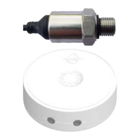
User Interface: 3 color LED, single touchless button
Environmental Conditions:
Shipment and Storage: -65 °C … 100 °C
Operation: - 10 °C … 50 °C
Rel. Humidity: 0...90 %
Support and Contact
Should you encounter any problem, please give us the opportunity to address it before returning this
product. Please check our website www.aqua-scope.com and particularly the support section for answers
and help. You can also send a message to [email protected].
While the information in this manual has been compiled with great care, it may not be deemed an
assurance of product characteristics. Aqua-Scope shall be liable only to the degree specified in the terms
of sale and delivery. The reproduction and distribution of the documentation and software supplied with
this product and the use of its contents is subject to written authorization from Aqua-Scope. We reserve
the right to make any alterations that arise as the result of technical development.
Phone: +372 (0) 6248002
eMail: [email protected]
Web: www.aqua-scope.com
Declaration of Conformity
Aqua-Scope Technology OÜ, Sakala 7-2, 10141 Tallinn, Republic of Estonia, declares that
this radio emitting device works on the following frequences:
Български С настоящото Aqua-Scope Technology OÜ декларира, че този тип
радиосъоръжение AQSWIE01 е в съответств ие с Директива 2014/53/ЕС. Цялостният текст на ЕС
декларацията за съответствие може да се намери н а следния интернет адрес: www.aqua-scope.com/ce.
Čeština Tímto Aqua-Scope Technology OÜ prohlašuje, že typ rádiového zařízení AQSWIE01 je v souladu se
směrnicí 2014/53/EU. Úplné znění EU prohlášení o shodě je k dispozici na této internetové adrese: www.aqua-
scope.com/ce.
Dansk Hermed erklærer Aqua-Scope Technology OÜ, at radioudstyrstypen AQSWIE01 er i overensstemmelse
med direktiv 2014/53/EU. EUoverensstemmelseserklæringens fulde tekst kan findes p følgende internetadresse:
www.aqua-scope.com/ce.
Deutsch Hiermit erklärt Aqua-Scope Technology OÜ, dass der Funkanlagentyp AQSWIE01 der Richtlinie
2014/53/EU entspricht. Der vollständige Text der EU-Konformitätserklärung ist unter der folgenden
Internetadresse verfügbar: www.aqua-scope.com/ce.
Eesti Käesolevaga deklareerib Aqua-Scope Technology OÜ, et kesolev raadioseadme tp AQSWIE01 vastab
direktiivi 2014/53/EL nuetele. ELi vastavusdeklaratsiooni tielik tekst on kttesaadav jrgmisel internetiaadressil:
www.aqua-scope.com/ce
English Hereby, Aqua-Scope Technology OÜ declares that the radio equipment type AQSWIE01 is in compliance
with Directive 2014/53/EU. The full text of the EU declaration of conformity is available at the following internet
Users and Installation Manual: Aqua-Scope Water Monitor (AQSWIE01)
Copyright © 2022 Aqua-Scope Technologies, Sakala tn 7-2, 10141 Tallinn, Estonia, www.aqua-scope.com

address: www.aqua-scope.com/ce
Español Por la presente, Aqua-Scope Technology OÜ declara que el tipo de equipo radioeléctrico AQSWIE01 es
conforme con la Directiva 2014/53/UE. El texto completo de la declaracin UE de conformidad está disponible en la
direccin Internet siguiente: www.aqua-scope.com/ce
Ελληνικά Με την παρούσα ο/η Aqua-Scope Technology OÜ, δηλώνει ότι ο ραδιοεξοπλισμός AQSWIE01 πληροί
την οδηγία 2014/53/ΕΕ. Το πλήρες κείμενο της δήλωσης συμμόρ φωσης ΕΕ διατίθεται στην ακόλουθη ιστοσελίδα
στο διαδίκτυο: www.aqua-scope.com/ce
Français Le soussigné, Aqua-Scope Technology OÜ, déclare que l'équipement radioélectrique du type AQSWIE01
est conforme la directive 2014/53/UE. Le texte complet de la déclaration UE de conformité est disponible
l'adresse internet suivante: www.aqua-scope.com/ce
Hrvatski Aqua-Scope Technology OÜ ovime izjavljuje da je radijska oprema tipa AQSWIE01 u skladu s Direktivom
2014/53/EU. Cjeloviti tekst EU izjave o sukladnosti dostupan je na sljedećoj internetskoj adresi: www.aqua-
scope.com/ce
Italiano Il fabbricante, Aqua-Scope Technology OÜ, dichiara che il tipo di apparecchiatura radio AQSWIE01
conforme alla direttiva 2014/53/UE. Il testo completo della dichiarazione di conformit UE disponibile al seguente
indirizzo Internet: www.aqua-scope.com/ce
Latviešu Ar šo Aqua-Scope Technology OÜ deklarē, ka radioiekārta AQSWIE01 atbilst Direktīvai 2014/53/ES. Pilns
ES atbilstības deklarācijas teksts ir pieejams šādā interneta v ietnē: www.aqua-scope.com/ce Lietuvių Aš, Aqua-
Scope Technology OÜ, patvirtinu, kad radijo įrenginių tipas AQSWIE01 atitinka Direktyvą 2014/53/ES. Visas ES
atitikties deklaracijos tekstas prieinamas šiuo internet adresu: www.aqua-scope.com/ce
Magyar Aqua-Scope Technology OÜ igazolja, hogy a AQSWIE01 típus rádiberendezés megfelel a 2014/53/EU
irányelvnek. Az EUmegfelelőségi nyilatkozat teljes szövege elérhető a következő internetes címen: www.aqua-
scope.com/ce
Malti B'dan, Aqua-Scope Technology OÜ, niddikjara li dan it-tip ta' tagħmir tar-radju AQSWIE01 huwa konformi
madDirettiva 2014/53/UE. It-test kollu tad-dikjarazzjoni ta' konformit tal-UE huwa disponibbli f'dan l-indirizz
talInternet li ġej: www.aqua-scope.com/ce
Nederlands Hierbij verklaar ik, Aqua-Scope Technology OÜ, dat het type radioapparatuur AQSWIE01 conform is
met Richtlijn 2014/53/EU. De volledige tekst van de EUconformiteitsverklaring kan worden geraadpleegd op het
volgende internetadres: www.aqua-scope.com/ce
Polski Aqua-Scope Technology OÜ niniejszym oświadcza, że typ urządzenia radiowego AQSWIE01 jest zgodny z
dyrektywą 2014/53/UE. Pełny tekst deklaracji zgodnośc I UE jest dostępny pod następującym adre sem
internetowym: www.aqua-scope.com/ce
Português O(a) abaixo assinado(a) Aqua-Scope Technology OÜ declara que o presente tipo de equipamento de
rádio AQSWIE01 está em conformidade com a Diretiva 2014/53/UE. O texto integral da declarao de conformidade
está disponível no seguinte endereo de Internet: www.aqua-scope.com/ce
Română Prin prezenta Aqua-Scope Technology OÜ declară că tipul de echipamente AQSWIE01 este în
conformitate cu Directiva 2014/53/UE. Textul integral al declarației UE de conformitate este disponibil la
următoarea adresă internet: www.aqua-scope.com/ce
Slovensko Aqua-Scope Technology OÜ potrjuje, da je tip radijske opreme AQSWIE01 skladen z irektivo
Users and Installation Manual: Aqua-Scope Water Monitor (AQSWIE01)
Copyright © 2022 Aqua-Scope Technologies, Sakala tn 7-2, 10141 Tallinn, Estonia, www.aqua-scope.com

2014/53/EU. Celotno besedilo izjave EU o skladnosti je na voljo na naslednjem spletnem naslovu: www.aqua-
scope.com/ce
Slovensky Aqua-Scope Technology OÜ týmto vyhlasuje, že rádiové zariadenie typu AQSWIE01 je v slade so
smernicou 2014/53/EÚ. Úplné EÚ vyhlásenie o zhode je k dispozícii na tejto internetovej adrese: www.aqua-
scope.com/ce
Soumi Aqua-Scope Technology OÜ vakuuttaa, että radiolaitetyyppi AQSWIE01 on direktiivin 2014/53/EU
mukainen. EUvaatimustenmukaisuusvakuutuksen täysimittainen teksti on saatavilla seuraavassa
internetosoitteessa: www.aqua-scope.com/ce
Svenska Härmed försäkrar Aqua-Scope Technology OÜ att denna typ av radioutrustning AQSWIE01
verensstmmer med direktiv 2014/53/EU. Den fullständiga texten till EUförsäkran om verensstämmelse finns på
följande webbadress: www.aqua-scope.com/ce
Disposal Guidelines
Do not dispose of electrical appliances as unsorted municipal waste, use separate collection
facilities. Contact your local government for information regarding the collection systems available.
If electrical appliances are disposed of in landfills or dumps, hazardous substances can leak into
the groundwater and get into the food chain, damaging health and well-being.
Users and Installation Manual: Aqua-Scope Water Monitor (AQSWIE01)
Copyright © 2022 Aqua-Scope Technologies, Sakala tn 7-2, 10141 Tallinn, Estonia, www.aqua-scope.com
Table of contents
Other Aqua-Scope Measuring Instrument manuals
Popular Measuring Instrument manuals by other brands

Apera Instruments
Apera Instruments SX716 user manual

E+E Elektronik
E+E Elektronik EE771 Series manual

Tektronix
Tektronix Keithley 4200A-SCS-PKA quick start guide

Magnescale
Magnescale DK812S Series instruction manual

SECO-LARM
SECO-LARM ENFORCER RM-R100-KB1Q Quick guide manual

Svantek
Svantek SVAN 958 user manual

FMC Technologies
FMC Technologies Smith Meter AccuLoad II Operator's guide

TDE Instruments
TDE Instruments Digalox DPM72-MP instruction manual

Ele
Ele 513-160 operating instructions

turck
turck BL ident TW-R30-B128-EX manual

WYLER
WYLER BlueCLINO Operator's manual

SKY PARAGLIDERS
SKY PARAGLIDERS SKYLIGHTER 3 user manual