Aquademy QUADRO THERMO Series User manual

TERMOSTATICO
QUADRO/TONDO THERMO
11-E0045
RV. 1
MANUALE D’INSTALLAZIONE e CABLAGGIO
INSTALLATION MANUAL

2
MISCELATORE TERMOSTATICO
DATI TECNICI
IT
portata a 38°C
CONDIZIONI D’UTILIZZO
Pressione di alimentazione 1 - 5 bar
Pressione consigliata 2 - 3 bar
Pressione minima 2 bar
Temperatura acqua fredda 5° - 25°C
Temperatura acqua calda 50° - 80°C
Temperatura massima 80°C
Temperatura consigliata 60° - 65°C
Differenza di pressione tra acqua calda e fredda 1bar max
FR
CONDITIONS DE FONCTIONNEMENT
Pression d’utilisation 1 - 5 bar
Pression conseillée 2 - 3 bar
Pression minimum 2 bar
Température de l’eau froide 5° - 25°C
Température de l’eau chaude 50° - 80°C
Température maximum de l’eau 80°C
Température conseillée 60° - 65°C
Difference de pression entre l’eau chaude et froide 1bar max
DE
TECHNISCHEDATEN
Betriebsdruck 1 - 5 bar
Empfohlene Betriebsdruck 2 - 3 bar
Min Druck 2 bar
Kaitwassertemperatur 5° - 25°C
Heißwassertemperatur 50° - 80°C
Max temperatur 80°C
Empfohlene Temperatur 60° - 65°C
Druckuntersched zwischen Kait und Wamwasser 1bar max
ES
CONDICIONES DE UTILIZO
Presión de alimentación 1 - 5 bar
Presión aconsejada 2 - 3 bar
Presión minima 2 bar
Temperatura agua fria 5° - 25°C
Temperatura agua caliente 50° - 80°C
Temperatura maxima 80°C
Temperatura aconsejada 60° - 65°C
Deferencia de presión entre agua caliente y fria 1bar max
EN
OPERATING CONDITIONS
Working pressure 1 - 5 bar
Recommendad pressure 2 - 3 bar
Minimum pressure 2 bar
Cold water temperature 5° - 25°C
Hot water temperature 50° - 80°C
Maximum temperature 80°C
Recommended temperature 60° - 65°C
Pressure variation cold/hot water 1bar max
57,5
34,5
77 min
90 max
124
54
143
114
185
205
11-E0045 TERMO:Layout 1 5-10-2011 12:16 Pagina 2

3
MISCELATORE TERMOSTATICO
MANUALE D’INSTALLAZIONE
INSTALLAZIONE
IT
EN
FR
DE
ES
Nella confezione sono presenti le prote-
zioni del blocco termostatico e deviato-
re: applicarle prima di cominciare l’in-
stallazione.
The packaging contains the thermosta-
tic block and diverter protection parts:
apply them before installing.
Dans la bôite de montage il y a les pro-
tection pour les corps du thermostati-
que et l’inverseur que on do it les appli-
quer sur les corps avant l’installation.
Die Verpackung enthält die
Schutzkapsel des Thermostat-Körpers
und des Umstellers zur Verwendung vor
der installation.
La confección contiene las protecciones
del bloqueo termostático y desviador:
tienen que ser aplicadas antes de
comenzar la instalación.
IT
EN
FR
DE
ES
Verificare che gli spazi ricavati nel muro
corrispondano per le dimensioni della
scatola e riferimento dei tubi di collega-
mento per la soluzione scelta.
Check that the spaces on the wall are
suitable for the chosen solution, consi-
dering the plastic box dimensions and
the references of the connecting pipes.
Verifier que l’espace dans le ur corre-
sponds aux dimensions de la bôite en
plastique et aux tuyaux de raccorde-
ments pour la solution choisie.
Die Löcher in der Wand müssen der
Größe der Kapsel und der Angabe der
Verbindungsschläuchen laut der ausge-
wählten Lösung entsprechen.
Comprobar que los espacios obteni-
dos en el muro corresponden por las
dimensiones de la caja y la referencia
de los caños de conexión por la solu-
ción escogida.
11-E0045 TERMO:Layout 1 5-10-2011 12:16 Pagina 3

4
MISCELATORE TERMOSTATICO
MANUALE D’INSTALLAZIONE
INSTALLAZIONE
IT
EN
FR
DE
ES
Verificare il parallelismo rispetto alla
parete sull’asse orizzontale per ottenere
la corretta posizione del prodotto.
Check that the product is fixed parallel
to the horizontal axis of the wall in order
to obtain the correct position.
Verifier le parallélisme en camporaison
de l’axe horizontal pour avoir l’exacte
position du produit.
Für eine korrekte installation muß das
produkt parallel zu der waagerechten
Achse sein.
Comprobar el paralelismo respeto a la
pared sobre la linea horizontal para obte-
ner la coreuta posición del producto.
IT
EN
FR
DE
ES
Verificare il parallelismo rispetto alla
parete sull’asse verticale.
Also check that the product is parallel to
the vertical axis of the wall.
Verifier aussi le parallelism en conparai-
son au mur sur l’axe vertical.
Es muß auch parallel zu der senkrechten
Achse sein.
Comprobar también el paralelismo
respeto a la pared sobre la linea vertical.
90°
90°
11-E0045 TERMO:Layout 1 5-10-2011 12:16 Pagina 4

5
MISCELATORE TERMOSTATICO
MANUALE D’INSTALLAZIONE
INSTALLAZIONE
IT
EN
FR
DE
ES
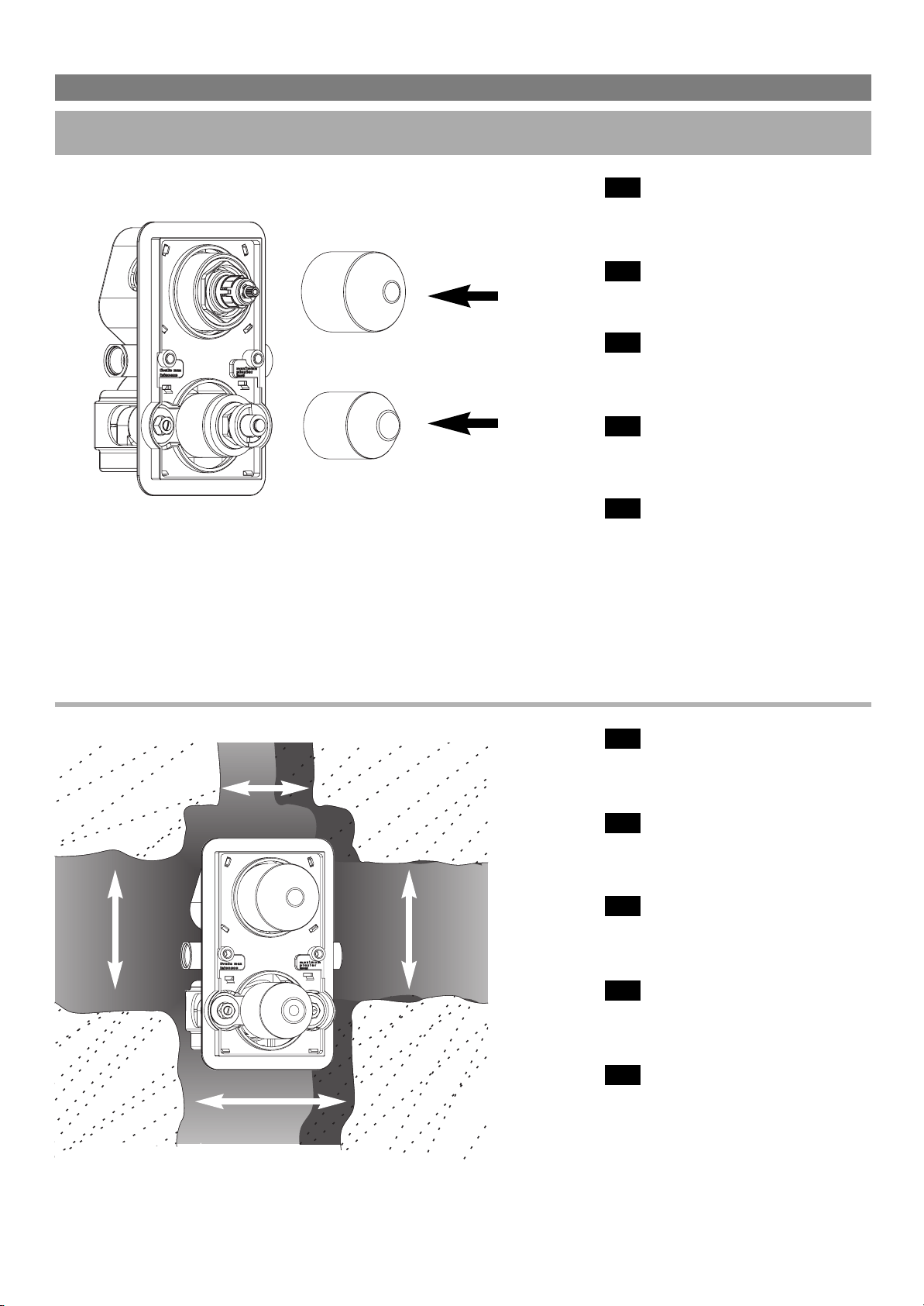
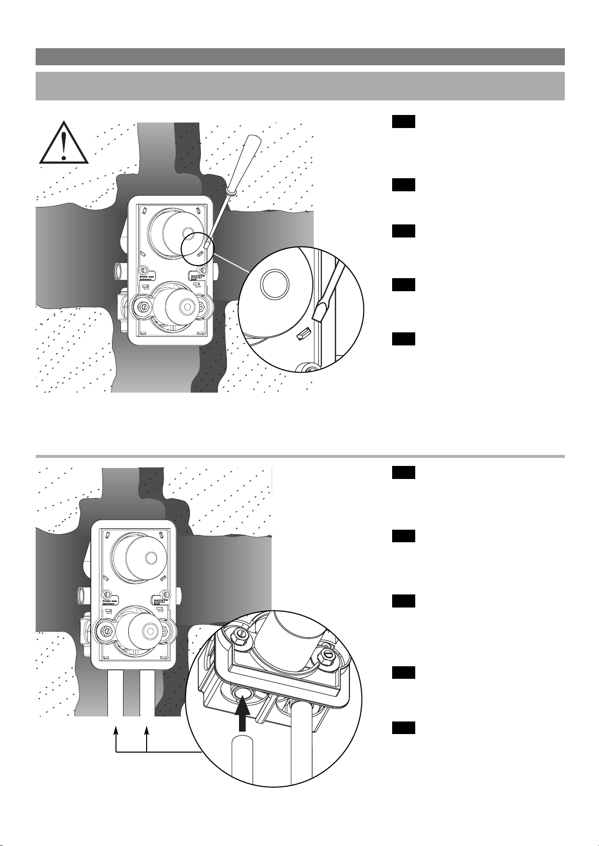
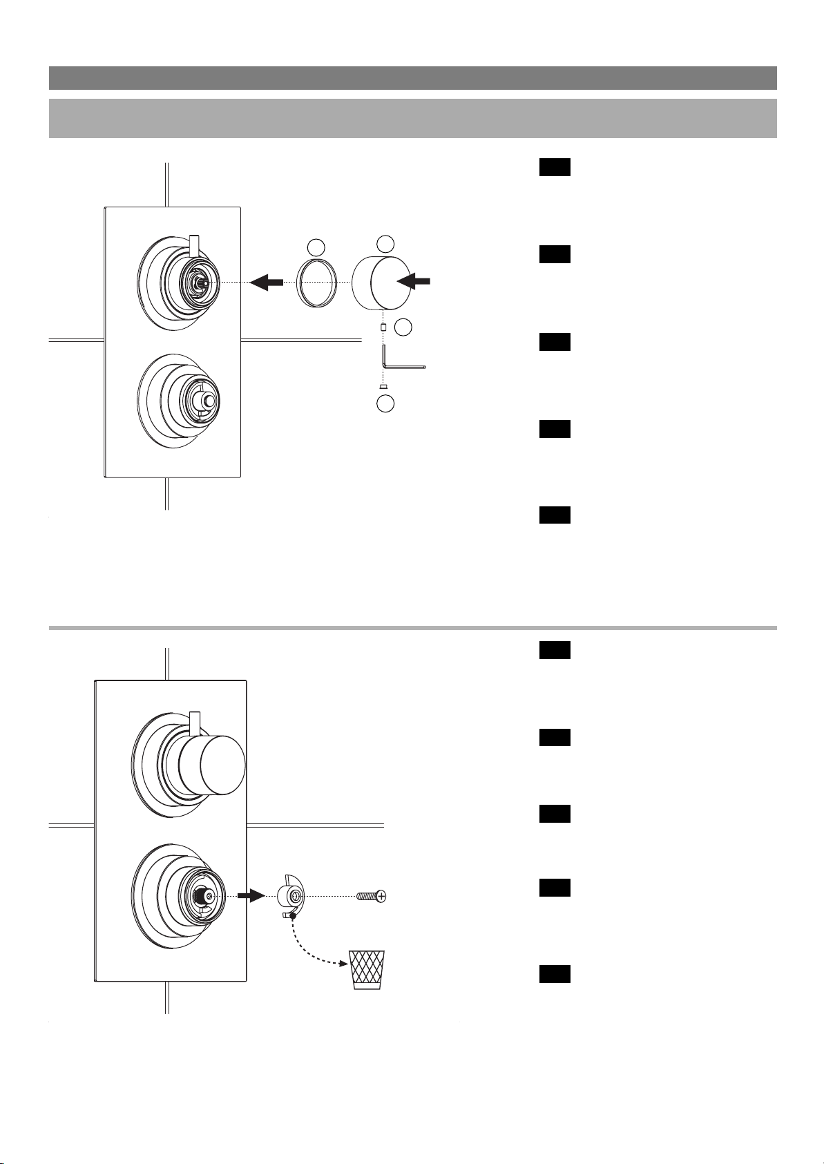
Non è necessario togliere la chiusura
della scatola di contenimento, ma nel
caso riteneste opportuna questa opera-
zione aiutarsi con un cacciavite in corri-
spondenza dei perni di ancoraggio.
It is not necessary to remove the plastic
box, but if you deem it necessary you
can help yourself with a screwdriver.
Il n’est pas necessaire d’enlever la böite
en plastique, mais si vous le souhaitez,
vous pouvez l’enlever en utilisant un
tournevis.
Der Verschluß der Schutzkapsel braucht
nicht beseltigt werden: falls notwendig,
kann man einen Schraubenzieher bei
den Verankerungzapfen benutzen.
No es necessario quitar la cierre de la
caja de contenimento, pero si fuera
oportuna esta operación ayudarse con
una destornillador en correspondencia
de los pernos de anclaje.
IT
EN
FR
DE
ES
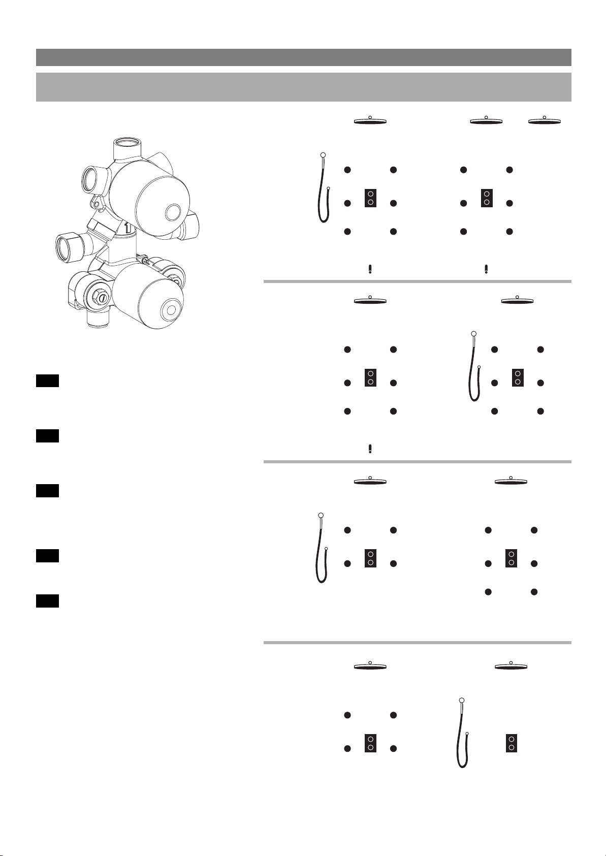
Collegare il corpo incasso alle tubature
seguendo le indicazioni presenti sul
pezzo, entrata acqua calda in corrispon-
denza del rosso, acqua fredda in corri-
spondenza del blu. Scegliere nelle pagi-
ne seguenti la soluzione 5/4/3/2 vie.
Conned the built-in body to the pipes
folowing the indications shown on the
piece, hot in-let connected with the red,
cold water connected with the blue. In
the following pages you can choose the
5/4/3/2 ways solution.
Connecter le corps à encastrer aux
tuyaux en suivant les indications sur la
piéce, l’eau chiude en correspondence
du rouge et l’eau froide en correspon-
dence du bleu. Choisir dans les pages
suivantes les solutions pour 5/4/3/2
voies.
Den UP-Körper laut Angaben mit den
Leitungen anschließen: Warmwasser
mit Rot und Kaltwasser mit Blau. Sie fin-
den in den folgenden Seiten die 5/4/3/2
–Wege-Lösung.
Conectar el cuerpo de empotrar a las
tuberias siguiendo las indicaciones que
hay sobre el articulo, entrada agua
caliente en correspondencia del rojo,
agua fria en correspondencia del azul.
Elegir en las paginas siguientes la solu-
ción 5/4/3/2 salidas.
x8
11-E0045 TERMO:Layout 1 5-10-2011 12:16 Pagina 5

6
MISCELATORE TERMOSTATICO
MANUALE D’INSTALLAZIONE
IT
EN
FR
DE
ES
Per la scelta della soluzione a 5/4/3/2
vie vi illustriamo alcuni esempi di instal-
lazione con le rispettive vie impiegate.
For the choice of 5/4/3/2 ways solution,
we show you some examples of instal-
lation and use of the respective ways.
Pour le choix de la solution à 5/4/3/2
voies dont nous vous illustrons quel-
ques exemples d’installation avec leurs
voies respectives utilisées.
5/4/3/2-Weg für die Auswahl der lösung,
wir zeigen einige Installationsbeispiele.
Para la elección de la solución de
5/4/3/2 vías, les mostramos algunos
ejemplos de instalación con las respec-
tivas vías.
VIE
VIE
VIE
VIE
[A]
A
B
D
C
C
B
C
C
E
A
B
C
C
B
C
C
D
A
B
B
B
B
A
B
C
C
B
C
C
D
AB
D
C
C
D
C
C
E
[E]
[D]
[C]
5
4
3
2
[B]
E
A
B
B
B
B
A
B
A
E
B
E
B
BB
11-E0045 TERMO:Layout 1 5-10-2011 12:16 Pagina 6

7
MISCELATORE TERMOSTATICO
MANUALE D’INSTALLAZIONE
INSTALLAZIONE
IT
EN
FR
DE
ES
Sigillare rispettando la bolla (pg. 4) e la
posizione del muro intonacato.
Sulla scatola di contenimento è indicata
la posizione massima rispetto al muro
intonacato.
Seal respecting the bubble level (pg. 4)
and the position of the plastered wall.
The correct position in relation to the
plastered wall is indicated on the pla-
stic box.
Cimenter le mitigeur en regardant le
niveau (pg. 4) et la position du mur
enduit.
Sur la bôite en plastique blanche est
indiquée la position en comparaison
du mur enduit.
Laut Bilder (pg. 4) mit einer Luftblase
den Körper versiegeln (beachten Sie
auch die Position der bestrichenen
Wand).
Auf der Schutzkapsel ist die position
zu der bestrichenen Wand gezeigt.
Cerrar respetando el paralelismo con
el suelo (pg. 4) y la posición del muro
revocado.
Sobre la caja de contenimento es indi-
cada la posición respeto al muro revo-
cado.
IT
EN
FR
DE
ES
Posare le piastrelle.
A muro finito e rivestito i perni filettati su
cui verrà agganciata la piastra dovranno
risultare meno sporgenti di 3-5 mm.
Place the tiles.
When the wall is finished and coverei,
the screw thread pins, where the cover-
plate will be installed, should not project
more than 3-5 mm.
Poser les carreaux.
Quand les carreaux sont bien posés
verifier que les piéces filetées sur le
squelles on doit fixer la rosáce, doivent
sortir du mur 3-5 mm.
Die Fliesen hinlegen.
Als die Wand ferting und ausgelegt ist,
müssen die geschnittene Zapfen,worauf
die Rosette montiert wird, weniger als 3-
5 mm. Vorstrecken.
Colocar los azulejos.
Cuando el muro serà acabado y revesti-
do los pernos roscados donde serà
enganchada la lastra tendrán que resul-
tar monos salientes de 3-5 mm.
3-5 mm
11-E0045 TERMO:Layout 1 5-10-2011 12:16 Pagina 7

8
MISCELATORE TERMOSTATICO
MANUALE D’INSTALLAZIONE
INSTALLAZIONE
IT
EN
FR
DE
ES
Rimuovere le protezioni in plastica.
Remove the plastic protections.
Enlever les protections en plastique.
Die plastikschutz wegnehmen.
Quitar las protecciones plásticas.
IT
EN
FR
DE
ES
Avvitare le ghiere.
Screw the dress rings.
Visser les caches écrou.
Den Ring anschrauben.
Atomillar los casquillos.
1
2
11-E0045 TERMO:Layout 1 5-10-2011 12:16 Pagina 8

9
MISCELATORE TERMOSTATICO
MANUALE D’INSTALLAZIONE
INSTALLAZIONE
IT
EN
FR
DE
ES
Applicare la piastra.
Apply the coverplate.
Positionner la rosace.
Die Rosette auflegen.
Aplicar la lastra.
IT
EN
FR
DE
ES
Posizionare la manopola (1) rispetto
alla brocciatura cartuccia deviatore.
Inserire l’inserto brocciato (2) sull’asta
del deviatore seguito dall’apposito
perno (3) di fissaggio.
Position the knob (1) with respect to the
diverter cartridge broaching.
Insert the broached insert (2) onto the
diverter rod followed by the proper fas-
tener stud (3).
Positionner la poignée (1) par rapport au
brochage du déviateur de la cartouche.
Insérer l’insert broché (2) sur la tige du
déviateur puis la cheville (3) de fixation
appropriée.
Den Handgriff (1) auf die Räumung
der Umstellkartusche setzen.
Den geräumten Einsatz (2) auf den
Schaft des Umstellers setzen und mit
dem entsprechendem Bolzen (3)
befestigen.
Coloque el mango (1) en relación al bro-
chado del cartucho de la llave de paso.
Introduzca el inserto brochado (2) en la
barra de la llave de paso seguido del
correspondiente perno (3) de fijación.
1
23
11-E0045 TERMO:Layout 1 5-10-2011 12:16 Pagina 9

10
MISCELATORE TERMOSTATICO
MANUALE D’INSTALLAZIONE
INSTALLAZIONE
IT
EN
FR
DE
ES
Montare la maniglia vitone (2) prece-
duta dall’anello antifrizione (1) e fis-
sarla con il grano M4 (3) adoperando
la chiave ch 2. Mettere l’apposito
coprivite cromato (4).
Mount the valve handle (2) preceded by
the anti-friction ring (1), and secure it by
the M4 dowel (3), using the ch. 2 key.
Put the proper chromium-plated screw
cover into place (4).
Monter la poignée du robinet à pointeau
(2) précédée de l’anneau anti-frottement
(1) et la fixer avec le grain M4 (3) au
moyen de la clé ch 2. Mettre le cache-
vis chromé adéquat (4).
Das Oberteil (2) auf dem Anlaufring (1)
montieren und mit Stift M4 (3) mit Hilfe
des Schraubschlüssels CH 2 befesti-
gen. Die verchromte Abdeckkappe auf-
setzen (4).
Monte la manilla del cuerpo (2) precedi-
da por el anillo antifricción (1) y fíjela con
el grano M4 (3) utilizando la llave ch 2.
Coloque el cubre tornillos cromado cor-
respondiente (4).
IT
EN
FR
DE
ES
Svitare la vite con taglio a croce che
tiene in posizione il particolare in plas-
tica rossa (indicato dalla freccia) riferi-
mento della temperatura a 38°.
Togliere il particolare rosso senza
muovere o spostare la parte bianca.
Unscrew the cross screw which keeps
the red plastic particular fixed (indica-
ted by the arrow) temperature refe-
rence 38°. Remove the red particular
without moving the white part.
Enlever la vis coupée à croisillon qui
fixe la piéces en rouge (indiqué par la
fléche) référence de la température a
38°. Enlever la piéce en rouge sans
enlever la partie blanche.
Die Kreuzförmige Schraube lösen, die
den roten Plastikeinsats (durch eine Pfeile
gekennzeichnet) hält. Sicherheitssperre
auf 38° C. Den roten Einsatz wegneh-
men, ohne den weiß Teil zu bewegen.
Destornillar el tornillo a cruz que tiene
fijado el particular en plàstico rojo
(indicado por la flecha) referencia de la
taradura a 38°. Quitar el particular rojo
sin mover la parte blanca.
M4
ch 2
12
3
4
11-E0045 TERMO:Layout 1 5-10-2011 12:16 Pagina 10

11
MISCELATORE TERMOSTATICO
MANUALE D’INSTALLAZIONE
INSTALLAZIONE
IT
EN
FR
DE
ES
Inserire il perno (1) per il fissaggio maniglia.
Applicare la maniglia con perno mobile rosso
(2) rivolto verso l’alto in corrispondenza dei
38° senza ruotare l’asta della cartuccia.
Fissare la maniglia tramite chiave ch 2 in
dotazione. Mettere l’apposito coprivite cro-
mato (3).
Insert the pin (1) for fastening the handle.
Attach the handle with the red movable pin (2)
facing up at 38°, without rotating the cartridge
rod. Fix the handle into place by the ch.2 key
supplied. Put in place the proper chromium-
plated screw cover (3).
Insérer la cheville (1) pour la fixation de la poi-
gnée. Appliquer la poignée avec la cheville
mobile rouge (2) tournée vers le haut à 38°
sans tourner la tige de la cartouche. Fixer la
poignée au moyen de la clé ch 2 fournie avec
l’équipement. Mettre le cache-vis chromé
adéquat (3).
Den Bolzen (1) zur Griffbefestigung einsetzen.
Den Griff mit dem beweglichen roten Bolzen
(2) nach oben gerichtet und in einem Winkel
von 38° aufsetzen, ohne dabei die Spindel der
Kartusche zu drehen, und dann mit dem mit-
gelieferten Schlüssel CH 2 anschrauben. Die
verchromte Abdeckung (3) anbringen.
Introduzca el perno (1) para fijar la manilla.
Inserte la manilla con el perno móvil rojo (2)
colocado hacia arriba 38º sin girar la barra del
cartucho. Fije la manilla utilizando la llave ch 2
que se suministra. Coloque el cubre tornillos
cromado correspondiente (3).
IT
EN
FR
DE
ES
A questo punto il montaggio pùò considerasi
completato.
At this point the assembly can be considered
as completed.
A cette étape, le montage peut être considéré
comme terminé.
Damit ist die Montage abgeschlossen.
En este momento, se puede considerar que el
montaje ha finalizado.
ch 2
2
3
1
11-E0045 TERMO:Layout 1 5-10-2011 12:16 Pagina 11

MISCELATORE TERMOSTATICO
MANUALE D’INSTALLAZIONE
INSTALLAZIONE MISCELATORE QUADRO
M4
M4
ch 2
12
3
456
7
89
IT
EN
FR
DE
ES
IT
EN
FR
DE
ES
Avvitare la ghiera (4).
Avvitare il cappellotto 5 fino alla bat-
tuta del corpo.
Portare a riscontro la ghiera (4) con la
base del particolare(5)
Screw the ring nut (4).
Screw on the cap nut (5) until tight
against the mixer body.
Match the ring nut (4) with the base of
the part.
Visser la bague (4).
Visser l’embout (5) jusqu’à rencontrer la
butée du corps mitigeur.
Positionner la bague (4) à la base de ce
détail (5).
Die Kopfmutter (4) anschrauben.
Den Deckel (5) bis zum Anschlag des
Mischer-Körpers anschrauben.
Die Kopfmutter (4) entsprechend der
Basis des Details (5) positionieren.
Apriete la tuerca (4).
Apriete la tuerca de apriete (5) hasta el
ajuste del cuerpo del mezclador.
Comprobar la tuerca (4) con la base del
elemento (5).
Per l’assemblaggio della versione quadra attenersi alle specifiche delle pagine seguenti. In figura sono numerate le
parti in progressione di montaggio.
For the assembly of the square version, follow the specific instructions on the following pages. In the figure each part is
given a number according to the assembly sequence.
Pour l’assemblage de la version cadre, se conformer aux spécifications des
pages suivantes. Sur la figure sont numérotées les parties en progression du montage.
Bei der Montage der viereckigen Version die Anweisungen auf den Vorseiten folgenden. Die Montage-Reihenfolge wird
in der Abbildung durch die Nummerierung wiedergegeben.
Para el montaje de la versión cuadrada, consulte las especificaciones de las páginas siguientes. En la figura, se enume-
ran en orden las acciones que se deben realizar para el montaje.
4 4
5
5
12
11-E0045 TERMO:Layout 1 5-10-2011 12:16 Pagina 12

13
MISCELATORE TERMOSTATICO
MANUALE D’INSTALLAZIONE
INSTALLAZIONE
M4
ch 2
M4
ch 2
13
14
15
16
17
18
10
19
M4
M4
ch 2
12
3
456
7
89
10
11 12
IT
EN
FR
DE
ES
In figura sono numerate le parti in pro-
gressione di montaggio.
In the figure each part is given a number
according to the assembly sequence.
Sur la figure sont numérotées les parties
en progression du montage.
Die Montage-Reihenfolge wird in der
Abbildung durch die Nummerierung
wiedergegeben.
En la figura, se enumeran en orden las
acciones que se deben realizar para el
montaje.
IT
EN
FR
DE
ES
Posizionare i particolari (6) e (7) mante-
nendo riferiti tra loro i Ø indicati per per-
mettere il serraggio con il grano M4.
Position the parts (6) and (7) keeping the
indicated Ø concentric, to allow locking
by the M4 dowel.
Positionner les détails (6) et (7) en main-
tenant en relation les diamètres Ø indi-
qués afin de permettre le serrage avec
le grain M4.
Die Details (6) und (7) unter Einhaltung
der angegebene Durchmesser so posi-
tionieren, um die Befestigung durch den
Stift M4 zu ermöglichen.
Coloque los elementos (6) y (7) mante-
niendo relacionados entre ellos los Ø
indicados para permetir el ajuste con el
grano M4.
6
7
Ø
11-E0045 TERMO:Layout 1 5-10-2011 12:16 Pagina 13

14
MISCELATORE TERMOSTATICO
MANUALE D’INSTALLAZIONE
MANUTENZIONE
2
2
3
3
IT
EN
FR
DE
ES
Dopo aver chiuso l’alimentatore gene-
rale dell’acqua è possibile eseguire
lavori di manutenzione e sostituzione.
Procedere allo smontaggio delle parti
esterne in sequenza inversa rispetto a
quella descritta. Una volta tolta la pias-
tra sarà possibile effettuare diverse
operazioni.
After closing the general water supply
unit, maintenance and replacement
works can be carried out. For the disas-
sembly of the external parts, follow in
reverse sense the sequence above.
Once the plate has been removed, it will
be possible to carry out different works.
Après avoir fermé l’alimentateur général
de l’eau, il est possible d’effectuer les
travaux d’entretien et de remplacement.
Procéder au démontage des parties
externes en séquence inverse par rap-
port à celle qui est ici décrite. Une fois la
plaque ôtée, il sera possible d’effectuer
différentes opérations.
Für Wartungsarbeiten den
Wasserhaupthahn schließen. Das
Zerlegen erfolgt in umgekehrte
Reihenfolge wie die oben beschrie-
benen Montage. Nach Entfernung
der Abdeckplatte sind verschiedene
Eingriffe möglich.
Después de haber cerrado el alimenta-
dor general del agua, es posible realizar
operaciones de mantenimiento y susti-
tución. Desmonte las partes externas
siguiendo las indicaciones, pero en sen-
tido contrario a las descritas para el
montaje. Una vez quitada la placa, será
posible llevar a cabo diferentes opera-
ciones.
IT
EN
FR
DE
ES
Per togliere la cartuccia deviatore
svitare la ghiera (1) con una chiave
esagonale 42 ed estrarre la parte da
sostituire.
To remove the diverter cartridge,
unscrew the ring nut (1) by a hexagon
key ch. 42, and remove the part to be
replaced.
Pour ôter la cartouche du déviateur,
dévisser la bague (1) avec une clé hexa-
gonale ch 42 et extraire la partie qui doit
être remplacée.
Zum Entfernen der Umstellkartusche die
Kopfmutter (1) mit einem
Sechskantschlüssel CH 42 aufschrau-
ben und die auszuwechselnde
Kartusche herausziehen.
Para quitar el cartucho de la llave de
paso, afloje la tuerca (1) con una llave
hexagonal ch 42 y extraiga la parte que
debe sustituir.
1
1
42 mm
11-E0045 TERMO:Layout 1 5-10-2011 12:16 Pagina 14

15
MISCELATORE TERMOSTATICO
MANUALE D’INSTALLAZIONE
MANUTENZIONE
IT
EN
FR
DE
ES
Sostituzione della cartuccia termosta-
tica utilizzando una chiave esagonale
da 26 mm con rotazione antioraria.
Procedere a ritroso per il rimontaggio.
Replacement of the thermostatic car-
trige through a 26 mm hexagonal key
with counterclock wise rotation.
Proceed back words to reassemble.
Changement de la cartouche ther-
mostatique en utilisant una clè exago-
nale de 26 mm en sans antihoraire.
Proceder à l’invers pour le remontage.
Die Thermostat-Kartusche durch einen
Sechskantschllussed von 26 mm mit
Linksdrehung ersetzen. Für die
Wiedermontage rückwafts vorgehen.
Sustitución del cartucho termostà tico
utilizando una ilave hexàgonal de 26
mm con movimento antihorario.
Proceder al contrario por remontaje.
IT
EN
FR
DE
ES
Pulizia dei filtri e verifica delle valvole
antiritorno utilizzando una chiave esa-
gonale da 13 mm con rotazione anti-
oraria. La presenza di impurità nel filtro
può ridurre l’erogazione d’acqua.
Procedere a ritroso per il rimontaggio
Filters’ cleaning and check of the non-
return valves through a 13 mm hexa-
gonal key with counterclock wise rota-
tion. Impurities in the filter may reduce
the water supply. Proceed backwards
to reassemble.
Nettoyer les filtres et les clapets antire-
tour avec une clé exagonale de 13 mm
en sens antihoraire. Des impuritées
presentes dans les filtres peuvent
reduire le débit. Proceder à l’invers
pour le montage.
Schmutzfänger spülen und
Ruckflußverhinderer durch einen
Sechskantschlüssel von 13 mm mit
Linksdrehung prüfen Die Anwesenheit
von Unreinheiten im Schmutzfänger
kann der Wasserauslauf vermindern
Für dei Wiedermontage rückwarts vor-
gehen.
llimpieza de lor filtros y comprobación
de las valvulas de no retorno utilizando
una ilave hexàgonal de 13 mm con
movimiento antihorario. La presencia
de impureza en el filtro puede reducir
la erogación del agua. Proceder al
contrario por el remontaje.
26 mm
13 mm
x2
11-E0045 TERMO:Layout 1 5-10-2011 12:16 Pagina 15

TERMOSTATICO
QUADRO/TONDO THERMO
11-E0045
RV. 1
This manual suits for next models
1
Table of contents
Other Aquademy Bathroom Fixture manuals
Popular Bathroom Fixture manuals by other brands

Helvex
Helvex H-3008 installation guide

OVE
OVE SYDNEY 60 installation manual

Arbonia
Arbonia CICSA Zeta Series user guide

Kohler
Kohler Englefield K-5627X Installation and care guide

Hans Grohe
Hans Grohe Jocolino 2jet 28760210 Assembly instructions

Signature Hardware
Signature Hardware Vilamonte 948600 quick start guide

Hewi
Hewi LifeSystem 802 80203110R99 Installation and operating instructions

Kohler
Kohler Rada PA-TF product manual

Pressalit
Pressalit MATRIX R485019 Mounting instruction

Helvex
Helvex Novus E45 installation guide

SANPLAST
SANPLAST ASPIRA SS0/ASP Installation instruction

newform
newform X-TREND Series instructions