1-10
Features
The Octopus 4000 incorporates several mecha-
nisms to protect your aquatic environment from
controller failure. For example, the controller is
engineered to overcome problems associated with
power fluctuations through the periodic re-sending of
control module commands to make sure that an X-
10 control is “latched” in the correct state.
Lighting System
The lighting system will support up to 16 indepen-
dent lighting times. Each channel has one ON and
OFF time per 24-hour period. With separate lighting
timers, there is a high degree of flexibility in setting
up your lighting system. See steps 4, 5, 17 and 22
for complete instruction.
System Hold
The H2O/S system hold software is a feature de-
signed to aid in the feeding of fish and invertebrates.
When the Octopus controller is put into feed mode,
all systems, except the Lighting and WaveMaker
systems, are shut down for a period of time selected
by the user. At the end of the specified time (user
selectable 0 to 60 minutes) all systems are turned
back on and will restart within 5 minutes. If desired,
the system hold option may be turned off by setting
the feed time to 0 minutes. The Octopus controller
will then no longer prompt you to enter the system
hold mode. See step 19 for complete instruction.
WaveMaker System
The H2O/S Dual Channel WaveMaker software
feature allows the Octopus 4000 to control two
independent wave or surge generation systems.
Each system supports two pumps which are driven
by Control Modules. The cycle time for each pump is
selected by the user, from 1-999 minutes (over 16
hours). See steps 4, 5, 18 and 22 for complete
instruction.
Alarm System
The H20/S alarm system software provides visual
and audible notification in the event that a monitored
parameter exceeds the user defined range. The
pager alarm system used in conjunction with a
modem provides remote alarm notification via a
digital pager. See steps 6 and 21 for complete
instruction.
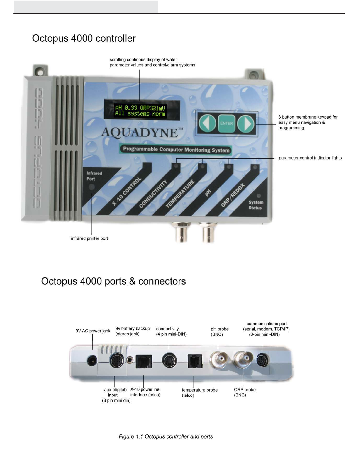
Infrared Printer Port
The infrared printer port located at the bottom left of
the face of the Octopus 4000 is standard. This port
provides access for the optional infrared datalog
reporting feature. Using the Infrared Printer data
collected by the Octopus 4000 can be printed out in
a variety of formats, including the current data, the
high and low points of data collected within the last
24 hours, 48 hours, or 1 week. Temperature, pH, and
ORP can be graphed. See #6 of the Operation And
Maintenance guide for additional information.