AquaLabo PONSEL Supratec S200TUr User manual

OWNER’S MANUAL
S200TUr Turbidimeter
AQUALABO
90 Rue du Professeur Paul Milliez
94506 Champigny-sur-Marne
Tel.: +33(0)155091010
E-mail: [email protected]
Internet: www.aqualabo.fr
Subject to technical changes. Errors and omissions excepted.

Table of Contents
Section Page
Specifications .................................................................................................... 1
1.0 Overview ........................................................................................................... 2
1.1 Unpacking and Inspection of the Instrument and Accessories ............. 2
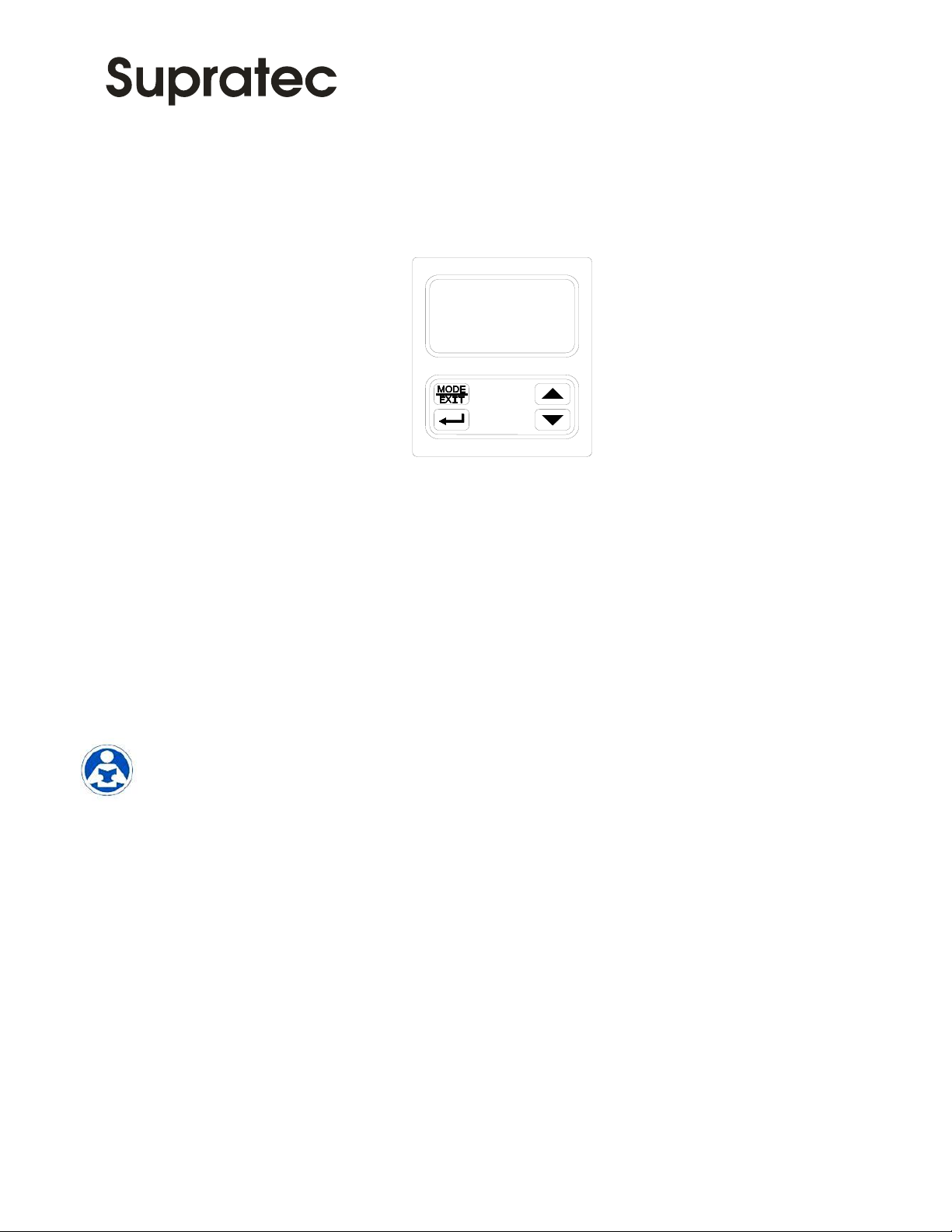
1.2 The Display .......................................................................................... 3
1.3 The Touch Pad ...................................................................................... 3
1.4 Vapor Purge........................................................................................... 3
2.0 Safety................................................................................................................. 3
2.1 Symbols Used in This Manual ............................................................. 4
3.0 Installation and Commissioning ....................................................................... 5
3.1 Mounting and Site Selection ................................................................. 5
3.2 Plumbing ............................................................................................. 6
3.2.1 Drain Vent ................................................................................. 7
3.2.2 Wetted Materials ....................................................................... 7
3.3 Electrical Connections .......................................................................... 7
3.3.1 Power ........................................................................................ 8
3.3.2 RS-485 ..................................................................................... 8
3.3.3 Relays ........................................................................................ 8
3.3.4 4-20 mA .................................................................................... 8
4.0 Operation .......................................................................................................... 9
4.1 Routine Measurement ........................................................................... 9
4.2 Security Access Feature ........................................................................ 9
5.0 Instrument Calibration .................................................................................... 10
5.1 Calibration Standards ......................................................................... 10
5.2 Calibration Procedures ....................................................................... 10
5.3 Calibration Error ................................................................................. 11
6.0 Instrument Offset ........................................................................................... 12
6.1 Indexing Calibration Cuvettes ............................................................ 13
6.2 Restoring Factory Settings .................................................................. 13
7.0 Instrument Configuration (CONFIG mode).................................................... 14
7.1 Selecting the Output (O/P) ................................................................. 14
7.2 Setting the 4-20 mA ............................................................................ 14
7.3 Configuring the Error Level ................................................................ 15
7.4 Configuring the RS-485 Port .............................................................. 15
7.5 Configuring the Alarms....................................................................... 16
7.5.1 Alarm 1.................................................................................... 16

Table of Contents (continued)
Section Page
7.5.2 Alarm 2 ................................................................................... 17
7.6 Offset Calibration ................................................................................ 17
7.7 Enabling the Security Access .............................................................. 18
7.8 Extended Settings ................................................................................ 18
7.9 Speed of Response............................................................................... 18
7.10 Displayed Resolution ......................................................................... 19
7.11 LCD Backlight Brightness .................................................................. 19
7.12 Setting the Units .................................................................................. 19
7.13 Ultrasonic Cleaning............................................................................. 20
7.14 RS- 485 Parameters ............................................................................. 20
7.15 Desiccant Alarm .................................................................................. 20
7.16 4 mA Adjustment ................................................................................ 21
7.17 20 mA Adjustment .............................................................................. 21
7.18 Saving Configuration Settings............................................................. 21
8.0 Additional Features and Options .................................................................... 22
8.1 Backlit LCD ........................................................................................ 22
8.2 Ultrasonic Cleaning............................................................................. 22
8.3 RS-485 Output..................................................................................... 23
8.3.1 Simple Communication........................................................... 23
8.3.2 Modbus Communication ......................................................... 24
8.4 Flow Alarm.......................................................................................... 24
8.5 Flow Controller ................................................................................... 24
8.6 Remote Panel Meter ............................................................................ 24
9.0 Troubleshooting & Maintenance .................................................................... 25
9.1 S200 TUr Fault Detection ................................................................... 25
9.2 System Fail Message .......................................................................... 25
9.3 Diagnostic Chart ................................................................................. 25
9.4 Technical and Customer Assistance ................................................... 26
10.0 Routine Maintenance....................................................................................... 27
10.1 Cleaning the Flow Through Cuvette .................................................. 27
10.2 Replacing or Installing the Desiccant Pouch ...................................... 27
10.3 Replacing the Source Lamp ............................................................... 27

-1-
Specifications
Measurement Range
0-10 NTU
0 –100 NTU
Accuracy
±2% of reading or ±0.02 NTU below 40 NTU whichever is greater
±5% of reading above 40 NTU
Resolution
0.0001 NTU (below 10 NTU)
Response Time
Adjustable
Display
Multi-Line Liquid Crystal Backlit Display
Alarms
Two Programmable, 120-240VAC 2A Form C Relay
Analog Output
Powered 4-20 mA, 600 drive
Communications Port
Bi-directional RS-485, Modbus
Maximum Water Pressure
Integral pressure regulator rated 1380kPa (200 PSI.) Also refer to
Flow Rate
Flow Rate
100 ml/min. –1 liter/min. (.026-.26 Gal/min)
Operating Temperature
1°C –50°C (34°F –122°F)
Wetted Materials
Nylon, Borosilicate Glass, Silicone, Polypropylene, Stainless Steel
Sample Temperature Range
1°C –50°C (34°F –122°F)
Power Supply
100 –240 VAC, 47 –63 Hz, 80VA
Insulation Rating
Double Insulated, Pollution Degree 2, Overvoltage Category II
Environmental Conditions
Not recommended for outdoor use.
Altitude up to 2000 meters
Up to 95 % RH (non-condensing)
Enclosure Rating
Designed to meet IP 66 /NEMA 4X
Regulatory Compliance
And Certifications
White Light Version compliant to U.S. EPA 180.1
Infrared Version compliant to ISO 7027
CE Approved, ETL listed to UL 61010-1 3rd Edition: 2012
ETL: Certified to CSA 22.2 No.61010-1-12: 2012
Shipping Weight
2.5 kg (5.5 lbs.)
Warranty
1 Years from date of manufacture

-2-
1.0 Overview
The S200 TUr process turbidimeter allows for the measurement of the turbidity of process
water on-line. The infrared S200 TUr was designed to meet the design criteria specified
in ISO 7027 and DIN 27027 for the measurement of the turbidity of a sample. Both
models have long life lamps.
The S200 TUr have ultrasonic cleaning.
A pressure regulator on the incoming line is a standard on all S200 TUr instruments and
will reduce pressures up to 1380kPa (200 PSI) down to (104kPa) 15 PSI.
1.1 Unpacking and Inspection of the Instrument and Accessories
The table below indicates the items in the turbidimeter shipment.
Item
Quantity
S200 TUr Turbidimeter c/w Field Terminal Box & Flow Through Assembly
1
Instruction Manual
1
Desiccant Pack
1
Tubing Kit: 1-shutoff clamp
1-backpressure valve
2-connecting tubing with fittings for flow through assembly
1-drain vent screw (used in pressurized systems)
1
Remove the instrument from the packing carton. Carefully inspect all items to ensure that
no visible damage has occurred during shipment. If the items received do not match the
order, please immediately contact the local distributor or the Supratec Customer Service
department.
1.2 The Display
Figure 1 illustrates all the items that can appear on the display. The upper row of the
display (1) is used for reporting the turbidity levels and to provide user guidance in the
customer setting routine. The lower row of the display (2) is used to communicate error
messages and provide user guidance. The display has two icons (3) that are used to
indicate the use of access code and offset mode. In addition, mode arrows (4) are used to
indicate the current instrument operating mode; AUTO (normal operation), CAL
(calibration) and CONFIG (configuration).
Figure 1 –Display used in the instrument.
All items used on the display are shown in this figure

-3-
1.3 The Touch Pad
Figure 2 illustrates the touch pad. The touch pad has four buttons: MODE/EXIT, , ,
and . The MODE/EXIT button is used to cycle between the three operational modes of
the instrument: CAL, CONFIG, and AUTO (Measurement) mode. The button enters
the option (or mode that is highlighted or chosen. The and buttons are used to change
settings.
Figure 2: Touch Pad
1.4 Vapor Purge
The S200 TUr is equipped with a continuous vapor purge system. A replaceable desiccant
pouch in the lower portion of the instrument dries the air. System heat is used to warm the
air. A fan inside the instrument continuously circulates heated dry air around the optical
well and the flow through cuvette. This feature eliminates the need for a dry purge line.
The S200 TUr monitors the replaceable desiccant pouch condition continuously. The LCD
display will show DESC on the lower line in the event that the desiccant pouch needs
replacement. Replacement desiccant pouches are available from Supratec or the local
representative. Refer to section 10.2 Replacing or installing the Desiccant Pouch.
The desiccant can activate an alarm to notify the operator of a saturated desiccant. See
section 7.15 Desiccant Alarm.
2.0 Safety
This manual contains basic instructions that must be followed during the commissioning,
operation, care and maintenance of the instrument. The safety protection provided by this
equipment may be impaired if it is commissioned and/or used in a manner not described in
this manual. Consequently, all responsible personnel must read this manual prior to
working with this instrument.
In certain instances Icons, have been highlighted to give further clarification to the
instructions. Refer to the Table of Contents to easily find specific topics and to learn
about unfamiliar terms.
2.1 Symbols Used In This Manual

-4-
This symbol identifies
hazards which, if not
avoided, could result in
minor or moderate injury or
damage to the equipment.
This symbol identifies
important information,
practices or actions.
This pictorial alert you to
the need read the manual,
possibly at a different
section.
This pictorial alerts you to
electricity, electrocution and
shock hazards.
This pictorial is used to
indicate useful tips and
information.

-5-
3.0 Installation and Commissioning
Prior to use for the first time, the supplied desiccant pouch will need to be installed. Refer
to section 10.2 Replacing or Installing the Desiccant Pouch.
3.1 Mounting & Site Selection
The instrument is designed for wall mounting. If wall mounting is not practical, the
instrument can be mounted on any suitable level surface. For ease of service there should
be about 20 cm (8”) free area above the instrument; this will ensure enough room for
calibration and cuvette maintenance. Choose a location that is easily accessible for
operation and service and ensure that the front display rests at eye level. The overall
mounting dimensions of the instrument are shown in Figure 3. The recommended
mounting screws are M6 (¼”) for the instrument enclosure and M4 (#8) for the field
terminal box. The S200 TUr is designed to have the field terminal box cradled under the
sensor portion of the instrument. It is recommended that the field terminal box be mounted
first, and then the rest of the instrument be mounted on top. The template on the last page
of this manual may be used to establish mounting hole locations.
Figure 3: Overall Mounting Dimensions of the Instrument
It is critical that the instrument be mounted as close as possible to the sampling point to
ensure a quick response time (within 2-3 meters (6-10 ft) of the sampling point).

-6-
3.2 Plumbing
The recommended plumbing for the instrument is shown in Figure 4. The instrument is
designed to require very little head pressure to operate; around 6.9kPa (1 PSI). The flow
through cuvette is rated for a flow of 100ml/min. –1 liter/min. (0.026-0.26Gal/min). The
integral pressure regulator is rated for a maximum pressure of 1380 kPa (200 PSI.). The
maximum allowable fluid temperature is 50°C (122°F).
Figure 4: Recommended Plumbing for the Instrument
The instrument is equipped to be plumbed using 4.75 mm (3/16”) ID, 8 mm (5/16”) OD
flexible tubing. Opaque tubing should be used if the tubing will be exposed to sunlight, to
prevent algae growth.
In figure 4, there are two flow devices shown. The one on the input side is a shutoff clamp
used during cuvette maintenance. The other device is a backpressure valve. Backpressure
may be required to prevent air from coming out of solution, which may be observed as
tiny air bubbles.

-7-
3.2.1 Drain Vent: The S200 TUr has been fitted with a drain vent in the “OUT” bulkhead
fitting. This fitting allows for atmospheric equalization, thus helping to alleviate bubble
formation in the cuvette. Refer to Figure 4.
Upon initial flow minor leakage may occur through the drain vent. This will subside once
normal flow is established.
For some high pressure systems, where the vent hole continuously leaks, a 6:32 seal screw
is provided which should be inserted into the vent hole and tightened.
The sensor drain tubing MUST be routed to a suitable drain. DO NOT reintroduce the
drain sample to the process stream. This is due to the fact that the wetted materials are not
FDA approved. See below for more information.
3.2.2 Wetted Materials: Supratec accepts no responsibility for damage caused by the
introduction of vapors, fluids or other materials into the instrument process stream which
is not compatible with the instrument’s wetted materials. A list of the wetted materials can
be found in the specifications on page 1 of this manual.
3.3 Electrical Connections
All of the electrical connections to the instrument are made through the field terminal box,
which should be located directly under the sensor portion of the instrument. The
connections are labeled within the terminal box and are self-descriptive (see Figure 5).
Please follow all local and government recommendations and methods for installation of
electrical connections to and between the instrument and other peripheral devices.
Plugs are inserted into the alarm and 4-20mA/RS-485 cable bulkheads when shipped, to
ensure a watertight seal. These plugs should be removed and discarded when cabling to
either of these connections.
The power cable bulkhead will accept cable diameters from 5.8mm (.230 in.) up to 10 mm
(.395 in.). All terminals are designed to accept wires in the range of 14-28 AWG. All
wires should be stripped to a length of 6 mm (¼”). A strain relief strap is provided to
reduce tension on the power terminals.
It is the user’s responsibility to assure that the watertight seal is maintained after the
terminal box has been wired for operation. If any of the bulkheads are not tightened
properly around a cable or plug, the ratings of the instrument will be jeopardized and there
is a possibility of creating a shock hazard.
Only qualified electricians should be allowed to perform the installation of the
instrument as it involves a line voltage that could endanger life.

-8-
Figure 5: Electrical Connections for the Instrument
3.3.1 Power: The instrument is equipped with a 100-240 VAC, 47-63 Hz switching power
supply; please verify that the line voltage falls within these specifications. It is
recommended that a circuit breaker be placed prior to the power connection to allow for
service. While making connections, refer to Figure 5. The S200 TUr is not supplied
with a power cord.
3.3.2 RS-485: The RS-485 half-duplex (2-wire) digital interface operates with differential
levels that are not susceptible to electrical interferences. This is why cable lengths up to
3000 ft can be implemented. The last device on each bus may require terminating with a
120-ohm resistor to eliminate signal reflection on the line. Do not run RS-485 cables in
the same conduit as power.
To prevent damage to the instrument, ensure that power is disconnected prior to making
connections. For ease of connecting, remove the plug in terminal block. Connections are
labeled beneath this termination.
3.3.3 Relays: The Alarm 1 and Alarm 2 relays are mechanical relays rated at 240 VAC
2A. Please note that the relays are labeled NO (Normally Open), NC (Normally Closed)
and C (Common). As these alarms are configured fail-safe, the normal condition is with
power applied to the S200 TUr and in a non-alarm condition. Operation of these alarms is
covered in section 7.5 Configuring the Alarms.
3.3.4 4-20 mA: The 4-20 mA output is driven by a 15 VDC power source and can drive
recorder loads up to 600 ohms. This 4-20 mA output is isolated from line power and earth
ground. Do not run 4-20 mA cables in the same conduit as power. Operation of this output
is covered in section 7.2 Setting the 4-20 mA. Optional transformer isolated outputs are
available as a factory installed option (Catalog No. 21045A).
The installation of the 4-20 mA isolator will render the RS-485 non-operational.
Ensure each instrument is not powered when connecting the 4-20 mA. To prevent damage
to the instrument, ensure that power is disconnected prior to making connections. For ease
of connecting, remove the plug in terminal block. Polarities of the connections are labeled
beneath this termination.

-9-
4.0 Operation
This process turbidimeter allows for the measurement of the turbidity of process water on-
line. The turbidity of the process water is usually reported in Nephelometric Turbidity
Units (NTU), but may be reported in Formazin Nephelometric Units (FNU). Readings
above 100 NTU are outside the range of this instrument. Readings above 100 NTU will
cause the display to flash indicating an over range condition
During normal operation, the instrument will have the arrow beside AUTO highlighted
with the current scale displayed on the lower row of the display and the measured reading
on the upper row of the display (see illustration below).
4.1 Routine Measurement
The following steps describe how to measure the turbidity of a sample using this
instrument:
1. Apply power to the instrument and allow the unit to warm up (typically 45 minutes –1
hour on initial commissioning).
2. When a continuous process stream is flowing through the instrument, the instrument
will display the measured turbidity level of the sample by displaying it on the LCD
screen. In addition, the equivalent signal is provided on the analog (4-20 mA) output,
or the digital output, depending on the options selected.
4.2 Security Access Feature
The instrument is equipped with a security access code feature that can be activated in the
configuration mode. If the security feature is enabled, the screen shown in the illustration
below will appear when the MODE/EXIT button is pressed.
The security code (333) must be entered to gain access to CAL or CONFIG menus.
Notice that the first number in the code is flashing; the flashing indicates that this is the
number to be changed. Use the or arrows to select the first of the three numbers in
the code and then press the button to accept the first number of the code. Now enter the
second number in the code. Proceed as with the first number followed by . Then repeat
the process for the third number in the access code, and finish with the button.
If the valid access code has been selected, the instrument will be directed to the calibration
mode. If the wrong access code is selected, the instrument will return to the AUTO mode.
Refer to section 7.7 Enabling the Security Access for more information.

-10-
5.0 Instrument Calibration
The instrument was calibrated and tested prior to leaving the factory. Therefore, it is
possible to use the instrument directly out of the box. Under normal conditions, re-
calibration is recommended at least once every three months
1
.
Relay contacts will change to the alarm state while the instrument is in the calibration
and/or in the configuration mode. While in the calibration mode, the instrument has a
time-out feature that automatically returns the system operation to the AUTO mode after a
fifteen (15) minute period of inactivity.
5.1 Calibration Standards
If the S200 TUr will be used over the entire range of .02 to 100 NTU a complete
calibration as described below will be required. If instrument accuracy is only required
below 10 NTU, such as potable water, a calibration may be performed using only a 10
NTU and a 0.02 NTU standard. To calibrate starting at the 10 NTU, press the button to
bypass the 100 NTU and proceed to Section 5.2 Calibration Procedures, step 5.
We recommend that the following materials be used during calibration to achieve the full-
scale accuracy stated in this manual:
1. 0.02 NTU Calibration Standard available from Supratec
2. 10.0 NTU Calibration Standard available from Supratec
3. 100 NTU Calibration Standard available from Supratec
5.2 Calibration Procedures
1. Select the calibration function of the instrument by pressing the MODE/EXIT button
once. The arrow beside CAL will be illuminated on the display. The lower display
shows alternating 100 (the value of the standard that is requested) and . The upper
display shows the real-time reading to allow the standard to be indexed. Refer to
section 6.1 for information on indexing cuvettes.
2. Remove the flow through unit.
3. Insert the requested 100 NTU standard. Index the standard to the lowest value on the
upper display.
4. Press the button to accept the calibration.
5. The lower display will count down the progress of the calibration step.
6. The lower display will now change to show alternating 10 and , requesting the 10.0
NTU standard.
1
The EPA recommends that on-line turbidimeters be calibrated with a primary standard at least once every three
months if they are to be used for EPA reporting.

-11-
7. If the alternating 10 and is not displayed, push the or until this display is
shown.
8. Insert the requested 10.0 NTU standard. Index the standard to the lowest value on the
upper display.
9. Press the button to accept the calibration.
10. The lower display will count down the progress of the calibration step.
11. The lower display will now change to show 02 and , requesting the 0.02 NTU
standard.
12. Insert the requested 0.02 NTU standard. Index the standard to the lowest value on the
upper display.
13. Press the button to accept the calibration.
14. The lower display will count down the progress of the calibration step.
15. The instrument will return to AUTO mode at the end the calibration.
During calibration, the fan inside the instrument is turned off to extend the life of the
desiccant. The fan will be turned on during calibration countdowns and after
returning to the AUTO mode or after five minutes, which ever comes first. It is
recommended that the measurement chamber be kept covered during the calibration
period and that the flow through cuvette be replaced immediately after the
calibration to prevent premature saturation of the desiccant.
5.3 Calibration Error
If the screen shown below, is displayed after calibration, the internal diagnostics have
determined that the calibration standards were either bad or that they were inserted in the
wrong order. Either check the standards and recalibrate or restore the factory calibration
see 6.2 Restoring Factory Settings. The instrument cannot be used without performing one
of these operations.
To recalibrate press the MODE key and start the calibration sequence again. To restore the
factory calibration, push and hold the button. Now push and release the then release
thebutton.

-12-
6.0 Instrument Offset
In certain instances, it may be desirable to use an offset factor to calibrate the instrument
rather than performing a physical calibration of the instrument (as described in section
5.2). This procedure is not recommended in lieu of regular instrument calibration but it
can be used in situations where the number of instruments used makes regular calibration
prohibitive. This calibration technique will make the instrument accurate only at turbidity
levels in the immediate vicinity of the grab sample and not in the full range of the
instrument. Note that the OFFSET icon will be illuminated whenever an offset used. The
maximum offset is ± 1.00 NTU. If instrument variation is greater than 1 NTU a full
calibration is recommended.
The procedures are as follows:
1. Collect a grab sample of the process water that is being monitored by the instrument
and record the turbidity reported by the instrument.
2. Take the grab sample and measure its turbidity using a laboratory turbidimeter
(contact the Supratec customer services department for examples of laboratory
turbidimeters).
3. Compare the turbidity reported by the instrument to that obtained in the laboratory. If
the readings are very close, then no offset adjustment or calibration is required and the
procedure may be stopped at this step. However, if the readings are substantially
different (but less that 1 NTU), continue on in this procedure to utilize the offset
option to improve the turbidity reading of the instrument so that it will agree with the
laboratory reading between calibrations.
4. Select the offset function of the instrument by pressing the MODE/EXIT button until
the arrow beside CONFIG is illuminated on the display. Refer to the following screen.
5. Push the button until OFST is displayed on the lower row.
6. At this point, the lower row of the display will indicate the operational status of the
offset function (On or OFF). Change this status by using the and buttons.
Once the desired operational status of the offset function has been set, press the
button to accept it. If the option was turned off, return to AUTO mode by pressing
MODE/EXIT.

-13-
7. If the option was turned On, the upper row will display the offset required. This will
add or subtract the value of the offset to the measured NTU value. As an example if
the S200 TUr measures the process at 0.16 NTU but the laboratory instrument read the
sample at 0.12 NTU, adding an offset of –0.04 would result in the S200 TUr
displaying 0.12 NTU.
Select the desired offset level using the and buttons. Once the desired level has
been set, press the button to accept it.
8. This completes the offset configuration.
9. At this point, the instrument will continue through the configuration (CONFIG) mode
of the instrument or press MODE/EXIT to return to the AUTO mode.
6.1 Indexing Calibration Cuvettes
To achieve the greatest accuracy, and account for normal scratches and aberrations in
cuvette glass when calibrating, Supratec recommends indexing the cuvettes.
Standards and standard kits purchased from Supratec are supplied with indexing rings.
The following steps allow repeatable indexing of calibration standards:
1. With the instrument in AUTO mode insert the standard.
2. Slowly rotate the standard, inside the optical well, one complete revolution (360º).
While rotating the standard slowly, observe the measured turbidity and locate the
position of the cuvette having the lowest reading.
3. With the calibration standard positioned at the location having the lowest turbidity
reading, install the Indexing Ring over the cap on the standard so that the pointer of
the Indexing Ring faces directly forward.
When using the standards in future, always insert the standard so that the pointer of the
indexing ring faces forward. Slowly rotate the standard back and forth about 5to find the
lowest point. The standard is now indexed and ready for use.
6.2 Restoring Factory Settings
If the instrument is unable to perform a calibration due to a low lamp output or a
calibration using the wrong standards, the instrument will display CAL on the lower row
of the display and Err on the upper row. The operator has two choices to correct this
problem. If the operator can determine whether a poor calibration or a low lamp caused
the problem, he/she can remedy the problem and recalibrate. If all else fails, the operator
may restore the factory calibration and configuration settings by performing the following
operation. Push and hold the button. Now push and release the then release
thebutton. Factory calibration and factory configuration have now been restored.
Restoring the factory settings allows the use of the S200 TUr with reduced accuracy.
The original problem still exists and must be determined and corrected before
accurate operation of the S200 TUr will be resumed.

-14-
7.0 Instrument Configuration (CONFIG mode)
The instrument has been designed to provide the ability to customize the instrument
according to needs at any time during normal operation. This mode has been split into
sub-menus to facilitate instrument configuration. This section describes how to use
each of the sub-menus to configure the instrument. While in the configuration mode, the
instrument has a time-out feature that automatically returns the system operation to the
AUTO mode after a fifteen (15) minute period.
Enter the CONFIG mode of the instrument by pressing the MODE/EXIT button until the
arrow beside CONFIG is illuminated, then press the button.
To exit the CONFIG mode, press the MODE/EXIT button.
7.1 Selecting the Output (O/P)
The first configuration selection is the O/P. The selections are 4-20 for the 4-20 mA
output, 485 for the RS-485 and OFF if no outputs are required. Select the desired output
by using the and buttons. Once the desired output has been set, press the button
to accept it. The next prompts will depend on the output selected.
7.2 Setting the 4-20 mA
If the 4-20 mA output was turned on, prompts to set the 4mA (4MA) and 20mA (20MA)
turbidity limits levels will be displayed. There is also a menu to adjust the error level
(ERLV). The first prompt will be the turbidity limit assigned to the 4 mA output level:
Select the turbidity level to assign to the 4MA using the and buttons.
The factory setting is 0.02 NTU.
Once the desired level has been set, press the button to accept it.
The 4MA can be set higher than the 20 MA level to invert the output current if
required. This may be required to control a dosing pump

-15-
The next, prompt will be the turbidity level assigned to the 20 mA output level (20MA) on
the lower row of the LCD display). Select the turbidity level to assign to the 20MA using
the and buttons. Once the desired level has been set, press the button to accept it.
The factory setting is 10.00 NTU.
7.3 Configuring the Error Level
In case of an error in the S200 TUr, the 4-20 mA reading can be used to indicate a
problem by sending the current to either 4.00 mA, 2.00 mA or 0 mA or OFF. In the case
of OFF, the 4-20mA is unaffected by any error condition. The factory default setting is
OFF. Select the desired ERLV by using the and buttons then press the button to
accept the desired error response.
7.4 Configuring the RS–485 Port
If the instrument is equipped with this option, and the I/O selection is changed to 485,
prompts will appear for setting the baud rate and the address.
Select the correct baud rate (1200, 2400, 4800, 9600, or 19200) for operation of the I/O
port by pressing the or buttons to change the displayed baud rate.
Press the button to continue on and select the desired instrument address using the or
buttons. Once the selection is satisfactory, press the button.
Select the address usingor buttons. Press the button to save.

-16-
To enable the Modbus mode, select ASCII or RTU.
7.5 Configuring the Alarms
Two relays are provided that are designed to operate as two independent programmable
alarms. Three types of information must be input to fully program each alarm:
1. The alarm function (HI, LO, OFF or Error)
2. The alarm set point (level at which the alarm activates)
3. The delay time for the alarm: the time that the set point must be exceeded prior to
alarm activation and the time before resetting the alarm (prevents chatter in the relay)
These three items are described below:
Alarm Function: The alarms can either be turned OFF or programmed to operate in one
of three different manners:
1. HI alarm: the relay changes state when the measured turbidity level is higher than the
programmed alarm level for a prescribed amount of time.
2. LO alarm: the relay changes state when the measured turbidity level is lower than the
programmed alarm level for a prescribed amount of time.
3. Error: the relay changes state when a system error occurs. If a system error occurs a
message will appear on the lower row of the screen describing the problem.
Alarm Set Point: The level at which an alarm activates is called the alarm set point. On
the instrument, the alarm set point is designated as “S/P”. The set point is adjustable to
any valid turbidity level over the range of the instrument in steps of 0.01 NTU.
Alarm Delay Time: The alarm delay times are used to prevent ringing of the alarm when
the measured turbidity level is close to the set point. The function of the delay times is as
follows:
Delay On: The turbidity level must exceed the alarm set point continuously for at least
this number of seconds before the alarm activates.
If the delay on time is set at 5 seconds and the process turbidity exceeds the set
point continuously for only 4 seconds, the alarm will not be activated.
However, process turbidity exceeds the set point continuously for 5 seconds or
more, the instrument will activate the alarm.
Delay Off: The turbidity level must not exceed the alarm set point continuously for at
least this number of seconds prior to deactivation of the alarm.
If the delay off time is set to 5 seconds and the process has exited out of the
alarm condition, the alarm will be reset only if the process is out of the alarm
condition for a continuous 5 seconds. Otherwise, the instrument will still
signal an alarm condition.
7.5.1 Alarm 1
Alarm 1 Function: The ALM1 is displayed and the display indicates the current function
of alarm 1 (HI, LO, OFF or Error). Use the orbuttons to cycle through and select
the desired function. Press the button to accept the selection.
If the alarm was turned OFF a prompt will appear to set up alarm 2 (go to section 7.5.2).

-17-
If, on the other hand, one of the other functionalities was selected a prompt will appear to
set the delay times.
Alarm 1 Set Point: This prompt is used to select the set point for this alarm; this is
indicated by “S/P” shown on the lower row of the display. Select the desired alarm level
by using the and buttons. Once the desired set point has been set, press the button
to accept it.
Alarm 1 Delay Times: Delay On: The following display will appear to allow to select
the number of seconds currently set for the “delay on” time.
The current selected number of seconds will be shown. Select the desired number of
seconds for the “delay on” time for this alarm using the and buttons. Once the
desired delay time has been set, press the button to accept it.
Delay Off: Next, the following display will appear to select the number of seconds
currently set for the “delay off” time.
The current selected number of seconds will be shown. Select the desired delay off time
for this alarm using the and buttons. Once the desired delay time has been set, press
the button to accept it. After the settings for alarm 1 have been completed, prompts will
allow for the set up of the information on alarm #2.
7.5.2 Alarm 2
Repeat the procedure listed in section 7.5.1 to set up the parameters for alarm 2. If one of
the other functionalities is selected, a prompt to set the delay times and the set point, as
with Alarm #1, will be displayed.
7.6 Offset Calibration
Refer to section 6.0 for more information on this selection.
Table of contents
Other AquaLabo Measuring Instrument manuals
Popular Measuring Instrument manuals by other brands

MARTINDALE
MARTINDALE LM195 instruction manual

Tektronix
Tektronix AM 503B Series instructions

Autonics
Autonics MP Series User Manual for Communication

Deif
Deif ADL-111Q96/xxVDC Series Installation & operation instructions

Sealey
Sealey AK9636D.V2 instructions

Blue Line Innovations
Blue Line Innovations PowerCost Monitor installation guide