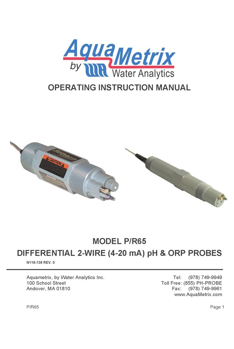
AquaMetrix Aqua-Check User manual

Aqua-Check™Water Analyzer
Operator’s Manual
4-30 Royal Crest Crt., Markham, On, L3R 9W8
Phone # 905-946-1064 Fax # 905-946-8064 Toll Free # 1-800-742-1413
www.aquametrix.com

Notice
The information contained in this document may be revised without notice.
AquaMetrix shall not be liable for errors contained herein or for incidental, or consequen-
tial, damages in connection with the furnishing, performance, or use of this material.
No part of this document may be reproduced or photocopied, or translated to another
language, without the prior written consent of AquaMetrix.
Rev. 2.1 — August 2000
AquaMetrix Part #291357
Printed in Canada
Copyright 2001–2004 AquaMetrix

Limited Warranty
AquaMetrix warrants each Aqua-Check Water Analyzer against defects in materials and
workmanship under normal use and service for a period of one (1) year (except for the
sensors and battery). Sensors are warranted for ninety (90) days. The battery is not covered
by this warranty. Equipment installed by AquaMetrix is warranted from the installation
date; all other equipment is warranted from the ship date. If purchaser schedules or delays
installation more than 90 days after delivery, then warranty period starts on the 91st day
from date of shipment. This warranty extends only to the original purchaser. AquaMetrix
will, at its option, repair or replace equipment that proves to be defective during the
warranty period, provided the equipment is returned to AquaMetrix at the expense of the
purchaser. Parts, labor, and return shipment to the customer shall be at the expense of
AquaMetrix.
Software and firmware designed by AquaMetrix for use with a CPU will execute its
programming instructions when properly installed on that CPU. AquaMetrix does not
warrant that the operation of the CPU, software, or firmware will be uninterrupted or error-
free.
This warranty shall not apply to defects originating from:
•Improper maintenance or operation by purchaser.
•Purchaser-supplied accessories or consumable.
•Modification or misuse by purchaser.
•Operation outside of the environmental and electrical products specifications.
•Improper or inadequate site preparation.
•Purchaser-induced contamination or leaks.
THE FOREGOING WARRANTY IS IN LIEU OF ALL OTHER WARRANTIES, EXPRESS
OR IMPLIED, INCLUDING BUT NOT LIMITED TO ANY WARRANTY OF MER-
CHANTABILITY, FITNESS, OR ADEQUACY FOR ANY PARTICULAR PURPOSE OR
USE. OI ANALYTICAL SHALL NOT BE LIABLE FOR ANY SPECIAL, INCIDENTAL,
OR CONSEQUENTIAL DAMAGES, WHETHER IN CONTRACT, TORT, OR OTHER-
WISE.
Any service requests or questions should be directed to the Technical Support Department

Table of Contents
Chapter 1: Introduction
Introduction.......................................................................................................1
Power.................................................................................................................1
Specifications....................................................................................................2
Options ..............................................................................................................3
Safety Information............................................................................................4
Chapter 2: Description of Components
Water Analyzer Meter ......................................................................................5
Water Analyzer Probe ......................................................................................6
Chapter 3: Operation
Removing the pH Boot ....................................................................................7
Preparing the Dissolved Oxygen Sensor........................................................7
Probe Connection .............................................................................................8
Connecting the Probe to the Meter...........................................................8
Disconnecting the Probe from the Meter.................................................8
Turning on the Water Analyzer ......................................................................8
Storing Readings ..............................................................................................9
Setup Instrument Mode....................................................................................9
Temperature Display .................................................................................9
pH Display..................................................................................................9
Oxygen Display .......................................................................................10
Oxygen Compensation............................................................................10
Oxygen Calibration Value ......................................................................10
Conductance Display...............................................................................11
Conductivity Compensation ...................................................................11
Pressure Compensation ...........................................................................12
Calibration.......................................................................................................12
Temperature Sensor Calibration .............................................................13
Dissolved Oxygen Sensor Calibration ...................................................13
pH Sensor Calibration .............................................................................15
Conductivity Sensor Calibration.............................................................15
Review Log.....................................................................................................16
Clear Log.........................................................................................................17
RS-232 Option ................................................................................................17
Timed Readings—Auto Logging ...........................................................17
RS-232 Interface Procedure ....................................................................18
Chapter 4: Maintenance
General Sensor Maintenance.........................................................................21
Dissolved Oxygen Sensor Maintenance.......................................................22
pH Electrode Maintenance ............................................................................22
Conductivity Sensor Maintenance ................................................................23
Temperature Sensor Maintenance.................................................................23
Probe Storage ..................................................................................................24

Chapter 5: Troubleshooting
Troubleshooting..............................................................................................25
Index
Index................................................................................................................27

Chapter 1 1
Introduction
Chapter 1
Introduction
The Aqua-Check Water Analyzer is a compact, rechargeable, battery-operated,
field instrument that simultaneously measures the dissolved oxygen level, pH,
conductivity, and temperature of water and aqueous solutions.
The operator can elect to display either uncompensated values or values that have
been compensated for external effects. In the compensated mode, the conductivity
and pH values will be compensated for temperature and the dissolved oxygen
reading for temperature, salinity, and atmospheric pressure.
All of these parameters, except atmospheric pressure, are measured with a single
compact probe that is equipped with a specific cable length (10', 25', 50', 100', 150',
and 200' are the standard lengths). This allows remote measurements to be taken,
without the need to draw a sample.
The Water Analyzer also contains a built-in measurement log to manually store
readings. This allows up to 199 sets of measurements to be saved in the field for
later review.
Power
The battery in the Water Analyzer will provide about 8 hours of continuous
operation (6 hours when using the RS-232 or barometer options). A low battery
signal will appear when approximately one hour of use is left. The meter has an
auto-shutoff safety feature that disconnects the power before the battery voltage
drops below a level dangerous to the memory. Recharge time for the battery is 5.5
hours. The Water Analyzer contains a back-up battery and will retain the stored
calibration information and the measurement log for at least 30 days without
external power.
An AC adapter/charger is provided for charging the Water Analyzer. An optional
12 V automobile cigarette lighter adapter is available. Extreme temperature during
recharging is not recommended. It is also recommended that the vehicle not be
started while the Water Analyzer is plugged in.
The Water Analyzer uses a sealed lead-acid gelled electrolyte battery. Unlike a
NiCad battery, these batteries can be recharged before they have been fully dis-
charged. Incomplete charge and discharge cycles will have little effect on battery
life or capacity. The battery is also protected from overcharge by an internal
battery maintenance circuit that allows the unit to be left connected to the AC
adapter/charger whether the meter is in use or not. The battery requires recharging
at least once every 3–4 months during extended periods of nonuse.

2Aqua-Check Water Analyzer Operator’s Manual
Rev. 2.1
Specifications
Data Storage
•The Water Analyzer stores 199 sets of readings. A log number is assigned
when the storage button is pressed and displayed when readings are being
reviewed.
Data Review
•Stored readings can be reviewed in Review Log Mode.
Battery
• 6 V rechargeable sealed lead acid.
Discharge Time
• 8 hours (6 hours with RS-232 option)
•Low battery indicator and automatic shutoff to prevent calibration and stored
reading memory loss
Sensor Unit Resolution Range Accuracy Compensation
pH pH 0.01 1–13 0.02 Temp (auto)
mV 1 ±500 ±2% None
Temp °C .1° 0–50 1 None
°F .1° 32–122 1.8 None
Cond mhos .1 µmho 0–99.9 ±3% Temp (auto)
1 µmho 0–999 ±3% (20° or 25°C)
.01 mmho 0–9.99 ±3% or none
.1 mmho 0–99.9 ±3%
Siemens .1 µS 0–99.9 ±3% Temp (auto)
1 µS 0–999 ±3% (20° or 25°C)
.01 mS 0–9.99 ±3% or none
.1 mS 0–99.9 ±3%
TDS .1 ppm 0–49.8 ±3% Temp (auto)
1 ppm 0–498 ±3% (20° or 25°C)
.01 ppt 0–4.98 ±3% or none
.1 ppt 0–49.8 ±3%
Oxygen ppm .1 ppm 0–20.0 ±2% to 5% Temp (auto),
Salinity, Opt.
%Sat 0 150.0 %Sat ±2% to 5% Temp (auto),
Salinity, Opt.
Press (auto)

Chapter 1 3
Introduction
Recharge Time
• 5.5 hours
Operation Temperature
• Meter: 0°–40°C
• Probe: 0°–50°C
Storage Temperature
• 5°–40°C
Dimensions
• Probe: 12" H x 1.5" D (30 cm x 3.8 cm)
•Meter: 7.5" H x 4.25" W x 1.5" D (19.2 cm x 10.9 cm x 3.8 cm)
Weight
• 5 lbs (2.27 kg)
Options
A kit of calibration standards is available. This kit contains quantities of pH 4, pH
7, and pH 10 buffers; pH boot solution; a set of conductivity standards (73.9 µS/
cm, 718 µS/cm, 6.67 µS/cm, and 58.6 µS/cm); a container of deionized water; a
package of oxygen sensor membranes; and oxygen filling solution.
Several factory installed hardware options are available:
• longer cable lengths,
• automatic barometric pressure compensation, and
•RS-232 computer interface with autodata logging capabilities.
Additional probes, of any cable length, may be ordered for a previously purchased
meter. Additional cable lengths cannot be retrofitted to existing probes.
The automatic barometric pressure compensation option may be added by the
factory to a previously purchased unit.
The RS-232 computer interface option allows parameter values, which have been
stored, to be downloaded via an RS-232 link to an IBM-compatible or Macintosh
computer. This enables the operator to incorporate data values directly into analy-
sis programs. Download software is provided for an MS-DOS®-based computer or
use your favorite communications software. Output is 1200 baud, and the output is
in ASCII format. The RS-232 option can be added by the factory at any time.

4Aqua-Check Water Analyzer Operator’s Manual
Rev. 2.1
Safety Information
Using the instrument in a manner not specified by the manufacturer may impair the
instrument’s safety protection. Whenever the safety protection of the Water
Analyzer has been compromised, disconnect the instrument from all power sources
and secure the instrument against unintended operation.
Operator Precautions
For operator safety, pay attention toWARNING and CAUTION statements
throughout the manual.
• A WARNING indicates a condition or possible situation that could result in
physical injury to the operator.
• A CAUTION indicates a condition or possible situation that could damage or
destroy the product or the operator’s work.
Warnings and precautions in this manual or on the instrument must be followed
during operation, service, and repair of the instrument. Failure to follow these
warnings and precautions violates the safety design standards and intended use of
the instrument. The manufacturer will not be liable for the operator’s failure to
comply with these warnings and precautions.
Safety Symbols
The following symbols are located on the instrument:
See accompanying instruction for more information.
Indicates a hot surface.
Indicates hazardous voltages.
Indicates earth (ground) terminal.

Chapter 2 5
Description of Components
Chapter 2
Description of Components
Water Analyzer Meter
[UP] and [DOWN] scroll through the menus and set values.
Battery Charger Inputconnects the meter to the battery charger.
ENTER selects menu items and skips calibration steps.
LCD Display displays operator prompts and measured values.
MODE selects the operating mode.
ON/OFF turns the Water Analyzer on and off.
Probe Connection connects the probe to the meter.
RS-232 Input/Outputjoins the RS-232 cable to the Water Analyzer Meter.
STORE stores displayed values in the measurement log and calibration informa-
tion.
LCD Display
Probe
Connection
Battery
Charger Input
RS-232
Input/Output
Figure 2.1. Water Analyzer Meter

6Aqua-Check Water Analyzer Operator’s Manual
Rev. 2.1
Water Analyzer Probe
Conductivity Electrodeconsists of 7/16" x 3" graphite embedded in an exoxy/
Delrin casing. It requires very little maintenance and may be replaced in the field.
Dissolved Oxygen Sensoris a gray PVC,7/16" x 4" polarographic type sensor
with a two-sectioned cavity filled with oxygen electrode filling solution. May be
replaced in the field.
Oxygen Sensor Cap (not shown) eliminates the need for careful membrane
stretching and placement. The membrane is made of a special material through
which gases but not liquids may pass. The membrane is integral to the cap, and the
cap is easily replaceable.
pH Sensor is an gray PVC, 7/16" x 3.75" electrode. The sensor should be kept wet
at all times. A boot is provided for this purpose. The recommended solution for
storage is 10% KCl in a pH 4 buffer. The pH sensor may be replaced in the field.
Probe Guard protects the sensors while allowing the test solution to flow past the
sensors. The probe guard is a 1.5" O.D. x 2.625" Delrin piece, held in place by the
guard retaining spring, which is compressed as the guard slides into place. Remove
the probe guard prior to removing any sensor. Make sure that the guard is in place
prior to using the probe.
Temperature Sensor is in a stainless steel housing. This sensor requires little
maintenance and is not field replaceable.
Probe Guard
Dissolved Oxygen
Sensor
Temperature
Sensor
Conductivity
Electrode
pH Sensor
Guard Retaining
Spring
Figure 2.2. Water Analyzer Probe
CAUTION:
Do not store the
pH electrode dry.
CAUTION:
Do not touch the
oxygen
membrane in the
oxygen sensor
cap—the
membrane will
not function
properly and the
oxygen sensor
cap will have to
be replaced.

Chapter 3 7
Operation
Chapter 3
Operation
This chapter describes the basics of taking a measurement with the Water Ana-
lyzer. Refer to Figures 2.1 and 2.2 in Chapter 2 when necessary.
Removing the pH Boot
Before a measurement can be made, the boot must be removed from the pH sensor.
The boot is a small polyethylene capsule that covers the pH sensor.
1. Remove the boot by gently sliding it off of the pH sensor body. Hold the pH
sensor body so that it is not pulled out of the probe as the boot is removed.
The boot is shipped from the factory filled with a boot solution of 10% KCl in
a pH 4 buffer.
2. When storing the probe after taking a measurement, be sure to replace the
boot. It should be filled with the boot solution. If none is available, the pH 4
buffer may be used.
As with any pH sensor, the solution in which the sensor’s pH electrode has been
stored will affect its calibration. If a solution other than 10% KCl in pH 4 buffer is
used as a storage solution, it will become necessary to soak the electrode in the
boot solution for at least one day prior to calibrating. This will ensure maximum
stability and accuracy.
Preparing the Dissolved Oxygen Sensor
1. Remove the probe guard.
2. Firmly pull the dissolved oxygen sensor straight out from the probe body. Do
not use any tools to pry the dissolved oxygen sensor out—this may cause
damage.
3. Fill the cavity section with oxygen filling solution, and insert the electrode
section and tighten. Reconnect the dissolved oxygen sensor to the probe and
slide it back into place.
4. The dissolved oxygen sensor will need to standardize for approximately 20
minutes prior to use. To standardize the sensor, place the probe in distilled
water or in a plastic bag with a wet sponge or cloth. The bag should be
secured so that a saturated air environment develops.
CAUTION:
Do not store the
pH electrode in
distilled water.
Do not store the
pH electrode dry.
CAUTION:
When the sensor
is removed from
the probe, do not
put the probe in
any water.
CAUTION:
Do not use any
tools to pry the
dissolved oxygen
sensor out.

8Aqua-Check Water Analyzer Operator’s Manual
Rev. 2.1
Probe Connection
It may become necessary to connect or remove the probe cable from the meter.
Connecting the Probe to the Meter
1. Line up the probe cable plug’s semicylindrical index with the corresponding
notch in the jack of the probe connection on the meter.
2. Gently push the plug into the jack—do not force it in.
3. Rotate the fluted locking ring of the probe cable plug about 1/3 turn to lock
the plug and jack connectors together.
Disconnecting the Probe From the Meter
1. Locate the connector that attaches the probe cable to the meter.
2. Rotate the fluted locking ring on the probe cable connector about 1/3 turn.
3. Gripping the cable connector body, gently pull the connector away from the
meter. Do not twist the connector or put any unnecessary strain on the probe
cable.
Turning on the Water Analyzer
1. Press the [ON/OFF] button. The meter should beep and display the message
“WATER ANALYZER Version 7.1.0.” After this time, it will begin to
display the current sensor readings. Units with factory installed barometers
will alternate between displaying the current temperature and the current
atmospheric pressure. If you do not want the pressure reading displayed, see
“Pressure Compensation” in this chapter.
2. To change the units that the information is displayed in, use the Setup Instru-
ment Mode. To select the Setup Instrument Mode, press the [MODE] key to
access the Mode menu. Press the [UP] and [DOWN] key until you reach the
“Setup Instrument” prompt. Press the [ENTER] key to activate the Setup
Instrument Mode. See “Setup Instrument Mode” in this chapter.

Chapter 3 9
Operation
Storing Readings
Pressing the [STORE] key while the Water Analyzer is displaying readings will
result in the data being stored in the measurement log. The numbered location
assigned to the logged reading will appear on the display, near the temperature
readout, for about three seconds. (Location numbers 1–99 are as is. Location
numbers 100–109 will be labeled A0–A9, and location numbers 110–119 will be
labeled B0–B9, and so on.)
Stored readings will remain stored even when the Water Analyzer is turned off.
Data does not need to be reviewed or downloaded in the field.
Setup Instrument Mode
To change the units that the information is displayed in, use the Setup Instrument
Mode. This mode allows the operator to select units for the pH, temperature,
pressure, conductivity, and oxygen readings. It also allows the operator to select
the extrinsic effects that the meter will automatically compensate for. To select the
Setup Instrument Mode:
1. Press the [MODE] key to access the Mode menu.
2. Press the [UP] and [DOWN] key until you reach the “Setup Instrument”
prompt. Press the [ENTER] key to activate the Setup Instrument Mode.
Temperature Display
The first prompt in the Setup Instrument Mode, “Temp. units:”, is used to select
either Fahrenheit or Celsius degrees for the temperature display. Press either the
[[UP] and [DOWN] key to toggle between °F and °C.
Press either the [ENTER] or the [STORE] key when the desired choice is dis-
played. This will save your selection and advance to the pH display.
pH Display
The second prompt in the Setup Instrument Mode, “pH in:”, is used to select either
pH or mV for the pH display. Press either the [UP] and [DOWN] key to toggle
between pH and mV.
Press either the [ENTER] or the [STORE] key when the desired choice is dis-
played. This will save your selection and advance to the Oxygen display.

10 Aqua-Check Water Analyzer Operator’s Manual
Rev. 2.1
Oxygen Display
The third prompt in the Setup Instrument Mode, “Oxygen in:”, is used to select
either ppm or percent of saturation for the oxygen concentration display. Press
either the [UP] and [DOWN] key to toggle between ppm and %.
Press either the [ENTER] or the [STORE] key when the desired choice is dis-
played. This will save your selection and advance to the Oxygen Compensation
prompt.
Oxygen Compensation
The fourth prompt in the Setup Instrument Mode, “Comp.Oxygen:”, allows control
of whether or not the oxygen readings will be corrected for salinity.
The polarographic sensor used by the Water Analyzer measures the chemical
activity of the oxygen in the water rather than its physical concentration. In dilute
solutions, the activity and concentration are indistinguishable from each other so
no problems arise. As the solution becomes increasingly concentrated with either
oxygen or other matter such as salts, the activity will increase above the physical
concentration. This is commonly referred to as salting out. At very high concentra-
tions, an error of 10% in the oxygen reading may be observed. Since the Water
Analyzer measures the salt concentration as well as the oxygen activity, it can
correct for the salt concentration to provide an actual physical oxygen concentration.
1. To enable the automatic correction of the oxygen reading for the salinity,
press the [‡] or [‰] key to display the answer YES. Press the [STORE] key.
2. To disable the automatic correction, press the [UP] and [DOWN] key to
display the answer NO. Press the [STORE] key. When measuring relatively
clean, fresh water, this correction will not affect the reading.
After the selection has been saved, the display will advance to the next item, which
allows you to select either a manually entered oxygen calibration value or an
automatically generated value.
Oxygen Calibration Value
The fifth prompt in the Setup Instrument Mode, “Automatic Ox Cal.” or “Manual
Ox Cal.”, selects whether the oxygen calibration is to be done with a manually
entered value or with an automatically determined one. The [UP] and [DOWN]
keys can be used to toggle between these two choices.
If “Manual Ox Cal.” has been selected during Oxygen Sensor Calibration, you will
be asked to specify the oxygen concentration in the water in which the calibration
is being performed. This is useful when strict correlation between the values from
the Water Analyzer and an older, less sophisticated oxygen meter is required.
If “Automatic Ox Cal.” is selected, you will be asked to specify the atmospheric
pressure when calibrating the dissolved oxygen sensor (see “Dissolved Oxygen

Chapter 3 11
Operation
Sensor Calibration” in this chapter). The Water Analyzer will calculate the appro-
priate value for the oxygen concentration based upon the water’s temperature and
the specified pressure. Once the desired selection is displayed, press either the
[ENTER] or the [STORE] key to record the choice and advance to the conductance
prompt.
Conductance Display
The sixth prompt in the Setup Instrument Mode, “Conductance:”, is used to select
the units used for displaying the conductance. The conductance may be displayed
in siemens (S) per cm, mhos (W) per cm, or TDS.
Due to the range of conductivity encountered, the values displayed will be in µS/
cm; mS/cm; µmho/cm or mmho/cm; or, for TDS readings, ppm or ppt.
1. Press the [UP] and [DOWN] key to cycle through the list of choices.
2. When the desired conductivity units are displayed, press either the [STORE]
or the [ENTER] key to save your selection.
3. If TDS is selected, the display will return to the Setup Instrument Mode. If
siemens or mhos is selected, the [STORE] or [ENTER] key will advance to
the conductivity compensation prompt.
Conductivity Compensation
The seventh prompt of the Setup Instrument mode is “Comp. Cond:”. This prompt,
which only appears if the conductivity is displayed in siemens or mhos, is used to
select the desired temperature and pressure compensation values for the conductiv-
ity readings.
The conductivity readings may be left uncompensated. In this case, the Water
Analyzer will read the actual conductivity of the solution. Be careful when cali-
brating the Water Analyzer when the “Comp. Cond:” is on since a conductivity
standard has its specified conductivity at only one temperature.
Alternatively, the conductivity readings may be corrected for temperature. Either
20°C or 25°C can be selected as the target temperature. When one of these is
selected, the displayed conductivity readings will be the conductivity the measured
solution would have at the target temperature if all of the conductivity is due to the
dissolved KCl. In reality, all of the conductivity will not be due to dissolved KCl,
so some slight systematic error will be present. This error is usually small enough
to neglect.
When the desired compensation has been entered, press either the [ENTER] or
[STORE] key to save the selection. This will advance to the next selection.
CAUTION:
Be careful when
calibrating the
analyzer when
the “Comp.
Cond:” is on
since a
conductivity
standard has its
specified
conductivity at
only one
temperature.

12 Aqua-Check Water Analyzer Operator’s Manual
Rev. 2.1
Pressure Compensation
The eighth and final prompt of the Setup Instrument Mode is “Pressure in:”. It is
used to set the pressure used to compensate for the partial pressure of oxygen in the
atmosphere.
Water Analyzers with barometers (factory installed) will first display “Disp.
Press.” Responding with YES will inform the meter that the current pressure
reading is to be displayed alternating with the temperature readings. A NO re-
sponse will result in the meter not displaying the current pressure reading.
The pressure will be displayed as torr (mm of Hg) or in (inches of Hg). Press the
[UP] and [DOWN] key to select the desired units. Press the [STORE] or [ENTER]
key to save the selection. The meter will then return to the display of the current
readings.
Calibration
Even though the Water Analyzer is calibrated before it leaves the factory, we
recommend calibrating it again prior to use. In addition, periodic recalibration is
recommended to ensure the accuracy of the displayed readings.
•Unless very accurate temperature measurements are to be made, the tempera-
ture sensor should never need recalibration. The Water Analyzer will meet its
temperature specification without any operator calibration.
Should the temperature sensor need to be recalibrated, it should be done prior
to any other calibration procedures. The same holds true for units with in-
stalled barometers. Once the temperature has been calibrated, the pressure
should be calibrated if required, prior to calibrating the pH, dissolved oxygen,
or conductivity sensor.
• The condition of the pH sensor will primarily depend upon its storage condi-
tions. Storing it in the recommended boot solution of 10% KCl in pH 4 buffer
will reduce the frequency of calibration.
• The dissolved oxygen sensor also requires periodic calibration. Organic matter
can foul the membrane pores, reducing the sensor’s effectiveness. Since the
sensor’s response is dependent upon the mass transport characteristics of the
membrane, as well as the condition of the surface of the electrode, it needs to
be recalibrated whenever the membrane is replaced or conditions warrant
recalibration.
• The conductivity sensor has less stringent calibration requirements than the pH
and dissolved oxygen sensors. Frequently, the factory calibration will suffice
for the life of the sensor; this is especially true if you are working with only
slightly conductive (less than 5 mS/cm) solutions.
CAUTION:
To reduce the
frequency of
calibration, store
the pH sensor in
the recommended
boot solution.

Chapter 3 13
Operation
Each of the four sensors in the probe (dissolved oxygen, pH, conductivity, and
temperature) are calibrated separately. When calibrating, allow the probe to sit in
the solution for 5 minutes and then allow up to 10 minutes for the ADC (Analog
Digital Conversion ) readout to stabilize. Then press the [STORE] key.
Temperature Sensor Calibration
The simplest sensor to calibrate is the temperature sensor. This is also the most
stable sensor, so it is unlikely that calibration will ever be required.
1. Immerse the probe into a solution and note the actual temperature of the
solution.
2. Turn the Water Analyzer on and allow the displayed readings to stabilize.
3. Press the [MODE] key, and press either the [UP] and [DOWN] key until you
reach the “Calibrate Temp” prompt. Press the [ENTER] key to select the
Calibrate Temp Mode.
4. The top line of the display will indicate the temperature set point. Press the
[UP] and [DOWN] key to change the displayed value to the actual temperature
of the solution into which the sensor is immersed. (The solution temperature
should be checked with an NIST traceable thermometer.)
5. The bottom line will show the ADC value. A stable readout (the ADC value
remains relatively constant for four counts), not the actual value, is important.
When the readout is stable, press the [STORE] key to calibrate the tempera-
ture sensor and store the calibration information. If you decide not to alter the
previously stored calibration information, press the [ENTER] key to skip this
step.
The Water Analyzer will resume displaying the measured values for temperature,
pH, conductivity, and oxygen.
We do not recommend calibrating the temperature sensor in air. The evaporation of
any water from the temperature sensor could keep its temperature significantly
lower than the surrounding air.
Dissolved Oxygen Sensor Calibration
The dissolved oxygen sensor used in the Water Analyzer requires frequent
recalibration for maximum accuracy.
The details of the calibration procedure depend upon whether Automatic or
Manual Oxygen Calibration is chosen in the Setup Instrument Mode.
1. Turn on the Water Analyzer and press the [MODE] key to access the Mode
menu.
2. Press either the [UP] and [DOWN] key until the “Calibrate Oxygen” prompt is
displayed. Press the [ENTER] key to select the Calibrate Oxygen Mode.
CAUTION:
The dissolved
oxygen sensor
requires frequent
recalibration for
maximum
accuracy.

14 Aqua-Check Water Analyzer Operator’s Manual
Rev. 2.1
Automatic Oxygen Calibration
When Automatic Oxygen Calibration (in units without internal barometers) has
been selected, the top line will display a prompt for the atmospheric pressure. This,
along with the temperature, is used to determine the solubility of oxygen in water.
1. Use the [UP] and [DOWN] keys to adjust the displayed value to the test site
atmospheric pressure.
Note: The barometric pressure as reported by radio and television stations is not
the correct atmospheric pressure to use. For standardization, the values
reported are corrected to sea level. To convert from the reported value to
the actual atmospheric pressure, you must know your altitude above sea
level. The local airport should be able to provide this information.
2. Once your altitude is known, the following table may be used to convert from
barometric to atmospheric pressure:
Altitude Correction Factor
–500 m 1.061
sea level 1.000
500 m 0.942
1000 m 0.887
1500 m 0.835
2000 m 0.785
3. Multiply the correction factor corresponding to the altitude by the standard-
ized barometer reading to get the actual atmospheric pressure. Contact the
dealer or the factory if additional correction factors are needed.
4. Once the correct pressure has been entered, press either the [ENTER] or
[STORE] key to save the value and move to the Air Sat Ox Cal step.
5. Wrap the probe in a wet cloth, or place it in a plastic bag with a few drops of
water and tie the bag shut. Do not touch the oxygen membrane. The object of
this operation is to have the oxygen and temperature sensors in a 100%
humidity environment.
Manual Oxygen Calibration
When manually calibrating the dissolved oxygen sensor, the top line of the display
indicates the oxygen concentration of the standard solution to be used. The [UP]
and [DOWN] keys may be used to adjust the displayed value to match that of the
standard solution. (The standard solution can be saturated air, approximately 9
ppm.) Place the probe in a standard solution and allow it to stabilize.
Once the ADC value stabilizes (approximately 15 minutes) for either of the above
methods (100% humidity or a given standard solution), press the [STORE] key to
complete the dissolved oxygen sensor calibration. To skip this step, press the
[ENTER] key and the previous calibration information will be used.
CAUTION:
Do not touch the
oxygen
membrane—the
membrane will
not function
properly, and the
oxygen sensor
cap will have to
be replaced.

Chapter 3 15
Operation
After the dissolved oxygen sensor calibration is complete, the Water Analyzer will
resume displaying the four measured parameters: temperature, pH, conductivity,
and oxygen.
pH Sensor Calibration
For maximum accuracy, the pH sensor is calibrated at three points: acid point,
base point, and neutral point.
1. Turn on the Water Analyzer and let the readings stabilize.
2. Completely immerse the pH sensor in a pH 4 buffer.
3. Press the [MODE] key to reach the Mode menu. Press either the [UP] and
[DOWN] key until “Calibrate pH” is displayed. Press the [ENTER] key to
select the Calibrate pH Mode.
4. The top line of the display will now read “pH low cal 4.00”. The [UP] and
[DOWN] keys can be used to adjust this to a different value if desired.
5. The bottom line of the display will show an ADC value. When the displayed
ADC value stabilizes, press the [STORE] key to save the calibration informa-
tion. To skip this step, press the [ENTER] key and the previous information
will be used.
After the pH low cal point has been determined, the pH mid cal and the pH high
cal points will be prompted for. We recommend that pH 4, pH 7, and pH 10 buffers
be used for calibrating the pH sensor.
While the solutions used are buffers and will remain reasonably stable in pH value
in spite of slight dilution or contamination, the greatest accuracy will be obtained
by using fresh, clean buffers. After a solution has been used to calibrate a pH point,
discard it.
Once the pH high point has been determined, the meter will resume displaying the
measured values for the temperature, conductivity, pH, and oxygen.
Conductivity Sensor Calibration
The conductivity meter contained within the Water Analyzer has four ranges of
sensitivity. The Water Analyzer automatically selects the appropriate range for
displaying the conductivity value. Each range must be calibrated separately. We
recommend that all four ranges be calibrated at the same time rather than the single
range you may be using.
1. Turn on the Water Analyzer and press the [MODE] key to access the Mode
menu.
2. Press either the [UP] and [DOWN] key until the “Calibrate Cond” prompt is
displayed. Press the [ENTER] key to select the Calibration Cond Mode.
Table of contents
Other AquaMetrix Measuring Instrument manuals
Popular Measuring Instrument manuals by other brands

Racelogic
Racelogic PBT-V1 quick start guide

SPI
SPI ABSOLUTE DIGITAL CALIPER Operation manual

Hanna Instruments
Hanna Instruments HI 2550 instruction manual

FMS
FMS RTM MP EMGZ482T.MP.24VDC Operation manual

Industrial Fiber Optics
Industrial Fiber Optics IF-RL05 Operator's manual

HP
HP 428B Operating and service manual