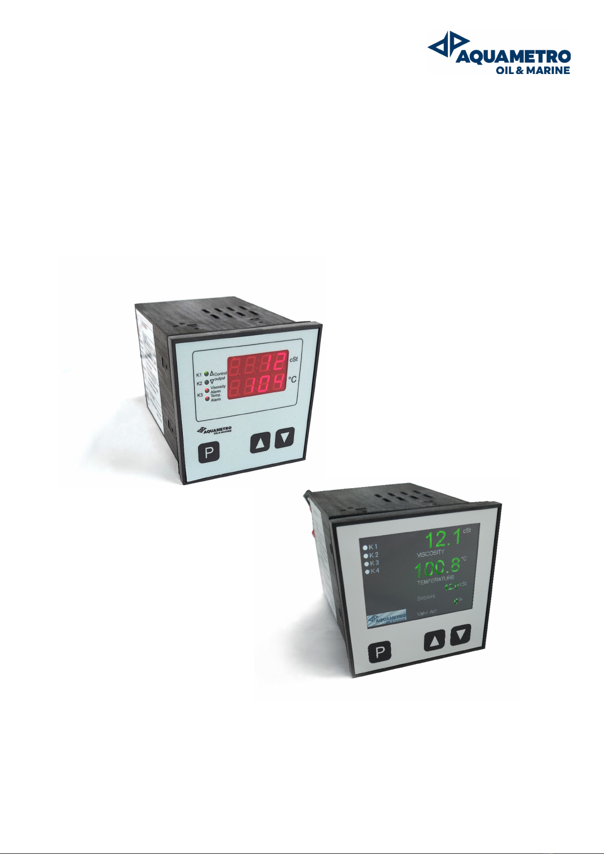
2 VCS – Viscosity Controller
Content
1Introduction.................................................................................................................................. 3
1.1 Liability disclaimer ...............................................................................................................................................................................3
1.2 Safety precautions...............................................................................................................................................................................3
1.3 Receiving and storage requirements...........................................................................................................................................4
2Application.................................................................................................................................... 4
2.1 Description of Viscosity Controller ...............................................................................................................................................4
3Controller installation / implementation................................................................................... 5
3.1 General.....................................................................................................................................................................................................5
3.1.1 Planning ............................................................................................................................................................................................6
3.1.2 Installation........................................................................................................................................................................................7
3.1.3 Electrical wiring ..............................................................................................................................................................................8
4Controller operation .................................................................................................................... 8
4.1 Putting into operation .......................................................................................................................................................................8
4.2 Display and operation level .............................................................................................................................................................9
4.3 Display operating status (VC622/722 only)...............................................................................................................................9
4.4 Parameter settings level.................................................................................................................................................................10
4.5 Configuration level...........................................................................................................................................................................11
4.6 Manual optimization ....................................................................................................................................................................... 14
5Maintenance and repair............................................................................................................. 15
5.1 Calibration ........................................................................................................................................................................................... 15
5.2 Service maintenance........................................................................................................................................................................ 15
5.3 Spare parts .......................................................................................................................................................................................... 16
6Troubleshooting ......................................................................................................................... 17
6.1 Controller problems and recommended actions................................................................................................................. 17
6.2 Process troubleshooting................................................................................................................................................................ 18
7Decommissioning, dismantling and disposal.......................................................................... 20
7.1 Decommissioning............................................................................................................................................................................. 20
7.2 Dismantling ......................................................................................................................................................................................... 20
7.3 Return of materials........................................................................................................................................................................... 20
7.4 Disposal ................................................................................................................................................................................................ 21
8Technical data............................................................................................................................. 21
8.1 Hardware characteristics................................................................................................................................................................21
8.2 Dimensional drawings .................................................................................................................................................................... 22
8.3 Electrical connection diagrams ................................................................................................................................................... 22
8.3.1 VC312 controller connection................................................................................................................................................. 22
8.3.2 VC622 (322/622/722) controller connection................................................................................................................... 27