IGM Professional Odyssey BAYLOAMS20 User manual

SSAAFFEETTYY WWAARRNNIINNGG
Only qualified personnel should install and service the equipment The installation, starting up, and servicing of heating, ventilating, and air-conditioning
equipment can be hazardous and requires specific knowledge and training Improperly installed, adjusted or altered equipment by an unqualified person
could result in death or serious injury When working on the equipment, observe all precautions in the literature and on the tags, stickers, and labels that
are attached to the equipment
August 2021 AACCCC--SSVVNN119900BB--EENN
Installation Guide
Head Pressure Control Kit
Odyssey™ Split System with Symbio™
Controls, 13 to 25 Tons
BBAAYYLLOOAAMMSS2200::
TTA156/180/201/240/251/300
TWA156/180/201/240
MOTOR
ON/OFF
N.O.
OK
LINE
120-600VAC
P/N ICM334-LF
MADE IN THE USA
C
Y1
Y2
REV. VALVE
P1&P2 BLK
HEAT
PUMP
N.C.
T AMBIENT
SETPOINT
155
35
psig 75 115
275
235
195
435
465 395
355
315
P1&P2 RED
P2 B.W.G.
P1 B.W.G.
1
Trane P/N
X13651682
LOAD
1
LINE
2
LOAD
2
LINE
3
LOAD
3
©2021 ACC-SVN190B-EN
Introduction
Read this manual thoroughly before operating or
servicing this unit
Warnings, Cautions, and Notices
Safety advisories appear throughout this manual as
required Your personal safety and the proper
operation of this machine depend upon the strict
observance of these precautions
The three types of advisories are defined as follows:
WARNING
Indicates a potentially hazardous situation
which, if not avoided, could result in death or
serious injury.
CAU
TION
Indicates a potentially hazardous situation
which, if not avoided, could result in minor or
moderate injury. It could also be used to alert
against unsafe practices.
NOTICE
Indicates a situation that could result in
equipment or property-damage only
accidents.
Important Environmental Concerns
Scientific research has shown that certain man-made
chemicals can affect the earth’s naturally occurring
stratospheric ozone layer when released to the
atmosphere In particular, several of the identified
chemicals that may affect the ozone layer are
refrigerants that contain Chlorine, Fluorine and Carbon
(CFCs) and those containing Hydrogen, Chlorine,
Fluorine and Carbon (HCFCs) Not all refrigerants
containing these compounds have the same potential
impact to the environment Trane advocates the
responsible handling of all refrigerants-including
industry replacements for CFCs and HCFCs such as
saturated or unsaturated HFCs and HCFCs
Important Responsible Refrigerant
Practices
Trane believes that responsible refrigerant practices
are important to the environment, our customers, and
the air conditioning industry All technicians who
handle refrigerants must be certified according to local
rules For the USA, the Federal Clean Air Act (Section
608) sets forth the requirements for handling,
reclaiming, recovering and recycling of certain
refrigerants and the equipment that is used in these
service procedures In addition, some states or
municipalities may have additional requirements that
must also be adhered to for responsible management
of refrigerants Know the applicable laws and follow
them
WWAARRNNIINNGG
PPrrooppeerr FFiieelldd WWiirriinngg aanndd GGrroouunnddiinngg
RReeqquuiirreedd!!
FFaaiilluurree ttoo ffoollllooww ccooddee ccoouulldd rreessuulltt iinn ddeeaatthh oorr
sseerriioouuss iinnjjuurryy
AAllll ffiieelldd wwiirriinngg MMUUSSTT bbee ppeerrffoorrmmeedd bbyy qquuaalliiffiieedd
ppeerrssoonnnneell IImmpprrooppeerrllyy iinnssttaalllleedd aanndd ggrroouunnddeedd
ffiieelldd wwiirriinngg ppoosseess FFIIRREE aanndd EELLEECCTTRROOCCUUTTIIOONN
hhaazzaarrddss TToo aavvooiidd tthheessee hhaazzaarrddss,, yyoouu MMUUSSTT ffoollllooww
rreeqquuiirreemmeennttss ffoorr ffiieelldd wwiirriinngg iinnssttaallllaattiioonn aanndd
ggrroouunnddiinngg aass ddeessccrriibbeedd iinn NNEECC aanndd yyoouurr llooccaall//
ssttaattee//nnaattiioonnaall eelleeccttrriiccaall ccooddeess
WWAARRNNIINNGG
PPeerrssoonnaall PPrrootteeccttiivvee EEqquuiippmmeenntt ((PPPPEE))
RReeqquuiirreedd!!
FFaaiilluurree ttoo wweeaarr pprrooppeerr PPPPEE ffoorr tthhee jjoobb bbeeiinngg
uunnddeerrttaakkeenn ccoouulldd rreessuulltt iinn ddeeaatthh oorr sseerriioouuss iinnjjuurryy
TTeecchhnniicciiaannss,, iinn oorrddeerr ttoo pprrootteecctt tthheemmsseellvveess ffrroomm
ppootteennttiiaall eelleeccttrriiccaall,, mmeecchhaanniiccaall,, aanndd cchheemmiiccaall
hhaazzaarrddss,, MMUUSSTT ffoollllooww pprreeccaauuttiioonnss iinn tthhiiss mmaannuuaall
aanndd oonn tthhee ttaaggss,, ssttiicckkeerrss,, aanndd llaabbeellss,, aass wweellll aass tthhee
iinnssttrruuccttiioonnss bbeellooww::
•• BBeeffoorree iinnssttaalllliinngg//sseerrvviicciinngg tthhiiss uunniitt,,
tteecchhnniicciiaannss MMUUSSTT ppuutt oonn aallll PPPPEE rreeqquuiirreedd ffoorr
tthhee wwoorrkk bbeeiinngg uunnddeerrttaakkeenn ((EExxaammpplleess;; ccuutt
rreessiissttaanntt gglloovveess//sslleeeevveess,, bbuuttyyll gglloovveess,, ssaaffeettyy
ggllaasssseess,, hhaarrdd hhaatt//bbuummpp ccaapp,, ffaallll pprrootteeccttiioonn,,
eelleeccttrriiccaall PPPPEE aanndd aarrcc ffllaasshh ccllootthhiinngg))
AALLWWAAYYSS rreeffeerr ttoo aapppprroopprriiaattee SSaaffeettyy DDaattaa
SShheeeettss ((SSDDSS)) aanndd OOSSHHAA gguuiiddeelliinneess ffoorr
pprrooppeerr PPPPEE
•• WWhheenn wwoorrkkiinngg wwiitthh oorr aarroouunndd hhaazzaarrddoouuss
cchheemmiiccaallss,, AALLWWAAYYSS rreeffeerr ttoo tthhee aapppprroopprriiaattee
SSDDSS aanndd OOSSHHAA//GGHHSS ((GGlloobbaall HHaarrmmoonniizzeedd
SSyysstteemm ooff CCllaassssiiffiiccaattiioonn aanndd LLaabbeelllliinngg ooff
CChheemmiiccaallss)) gguuiiddeelliinneess ffoorr iinnffoorrmmaattiioonn oonn
aalllloowwaabbllee ppeerrssoonnaall eexxppoossuurree lleevveellss,, pprrooppeerr
rreessppiirraattoorryy pprrootteeccttiioonn aanndd hhaannddlliinngg
iinnssttrruuccttiioonnss
•• IIff tthheerree iiss aa rriisskk ooff eenneerrggiizzeedd eelleeccttrriiccaall
ccoonnttaacctt,, aarrcc,, oorr ffllaasshh,, tteecchhnniicciiaannss MMUUSSTT ppuutt
oonn aallll PPPPEE iinn aaccccoorrddaannccee wwiitthh OOSSHHAA,, NNFFPPAA
7700EE,, oorr ootthheerr ccoouunnttrryy--ssppeecciiffiicc rreeqquuiirreemmeennttss
ffoorr aarrcc ffllaasshh pprrootteeccttiioonn,, PPRRIIOORR ttoo sseerrvviicciinngg
tthhee uunniitt NNEEVVEERR PPEERRFFOORRMM AANNYY SSWWIITTCCHHIINNGG,,
DDIISSCCOONNNNEECCTTIINNGG,, OORR VVOOLLTTAAGGEE TTEESSTTIINNGG
WWIITTHHOOUUTT PPRROOPPEERR EELLEECCTTRRIICCAALL PPPPEE AANNDD
AARRCC FFLLAASSHH CCLLOOTTHHIINNGG EENNSSUURREE
EELLEECCTTRRIICCAALL MMEETTEERRSS AANNDD EEQQUUIIPPMMEENNTT AARREE
PPRROOPPEERRLLYY RRAATTEEDD FFOORR IINNTTEENNDDEEDD
VVOOLLTTAAGGEE
ACC-SVN190B-EN 3
WWAARRNNIINNGG
FFoollllooww EEHHSS PPoolliicciieess!!
FFaaiilluurree ttoo ffoollllooww iinnssttrruuccttiioonnss bbeellooww ccoouulldd rreessuulltt iinn
ddeeaatthh oorr sseerriioouuss iinnjjuurryy
•• AAllll TTrraannee ppeerrssoonnnneell mmuusstt ffoollllooww tthhee
ccoommppaannyy’’ss EEnnvviirroonnmmeennttaall,, HHeeaalltthh aanndd SSaaffeettyy
((EEHHSS)) ppoolliicciieess wwhheenn ppeerrffoorrmmiinngg wwoorrkk ssuucchh aass
hhoott wwoorrkk,, eelleeccttrriiccaall,, ffaallll pprrootteeccttiioonn,, lloocckkoouutt//
ttaaggoouutt,, rreeffrriiggeerraanntt hhaannddlliinngg,, eettcc WWhheerree llooccaall
rreegguullaattiioonnss aarree mmoorree ssttrriinnggeenntt tthhaann tthheessee
ppoolliicciieess,, tthhoossee rreegguullaattiioonnss ssuuppeerrsseeddee tthheessee
ppoolliicciieess
•• NNoonn--TTrraannee ppeerrssoonnnneell sshhoouulldd aallwwaayyss ffoollllooww
llooccaall rreegguullaattiioonnss
Copyright
This document and the information in it are the
property of Trane, and may not be used or reproduced
in whole or in part without written permission Trane
reserves the right to revise this publication at any time,
and to make changes to its content without obligation
to notify any person of such revision or change
Trademar s
All trademarks referenced in this document are the
trademarks of their respective owners
Revision History
Jumper images updated for TTA and TWA models
IInnttrroodduuccttiioonn

ACC-SVN190B-EN 5
Pre-Installation
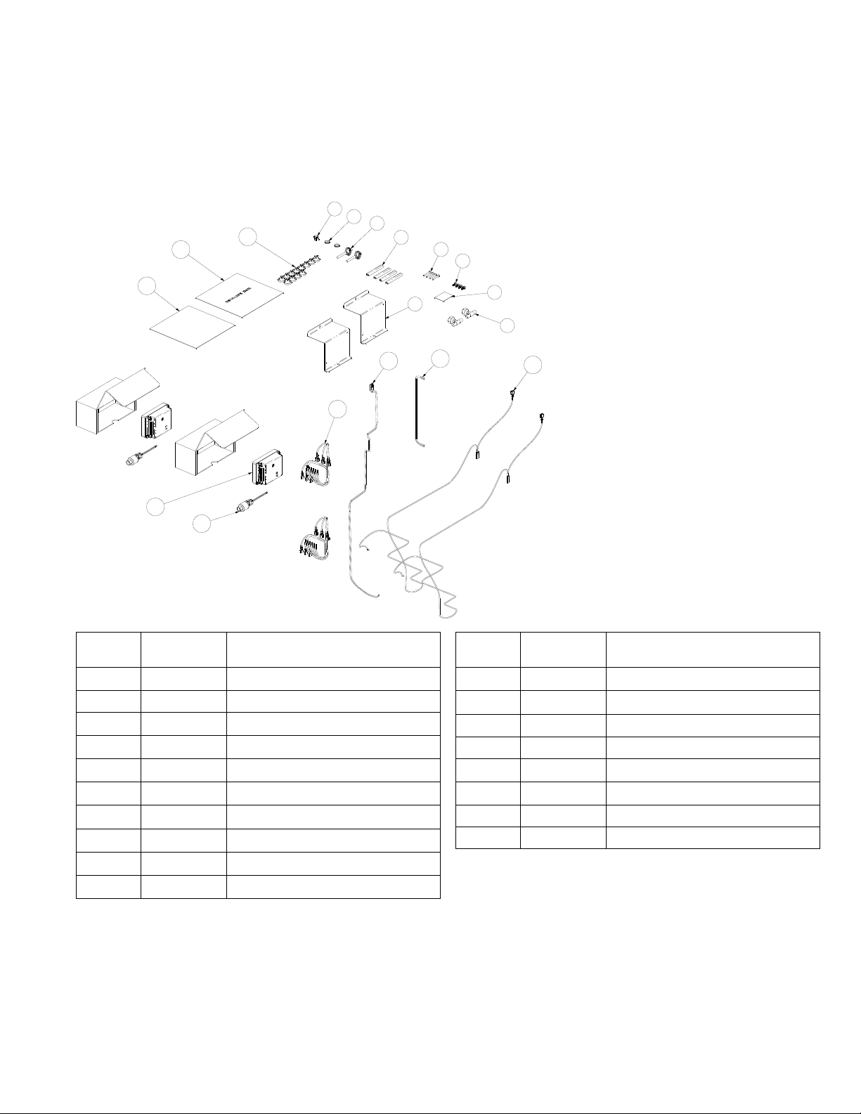
Parts List
Figure 1. Parts list
3
11
1
2
4
5
6
7
8
9
10
12
13
14
15
16
17
18
Item
Number Quantity Description
1 1 Pop-in Wire Tie
2 2 Grommet
3 2 Sensor; Thermistor Probe
4 4 Edge Protector
5 4 Screw; # 8-32 X 1.25 Pan Head
6 4 Screw; # 10-16 X .50 Hex Head
7 1 Label; Information BAYLOAMS20
8 2 Tee; Pressure Tap
9 2 Bracket; Support
10 2 Harness; Low Ambient Kit - SOV
Item
Number Quantity Description
11 1 Harness; 2 Kits Jumper
12 1 Harness; 24V UC Board to Loam
13 2 Harness; Power
14 2 Transducer
15 2 Controller; Low Ambient
16 1 Supplemental Wiring Diagram
17 1 Installation Guide
18 12 Wire Tie

6ACC-SVN190B-EN
General Information
Table 1. Low ambient controller specifications
Volts, AC 208, 240, 380, 415, 480, 600
Control Voltage 18-30 Vac
Frequency 50-60 Hz
Operating Temperature -40ºF to 140ºF (-40ºC to
60ºC)
Full Load Amps 10 Amps
Transducer Pressure Control
Range
0-500 psi
Disable Evaporator Defrost Control
IImmppoorrttaanntt:: For proper operation of the low ambient
head pressure control accessory in an
Odyssey condenser, the Evaporator Defrost
Control (EDC) function M ST be disabled.
To disable the EDC, navigate to the "Utilities" menu on
the Symbio™700 user interface and change the
configuration parameter "Evaporator Defrost Control"
to "Disabled" The Symbio Service and Installation
mobile application can also be used to edit this
parameter
PPrree--IInnssttaallllaattiioonn
ACC-SVN190B-EN 7
Installation
Controller
WWAARRNNIINNGG
HHaazzaarrddoouuss VVoollttaaggee ww//CCaappaacciittoorrss!!
FFaaiilluurree ttoo ddiissccoonnnneecctt ppoowweerr aanndd ddiisscchhaarrggee
ccaappaacciittoorrss bbeeffoorree sseerrvviicciinngg ccoouulldd rreessuulltt iinn ddeeaatthh oorr
sseerriioouuss iinnjjuurryy
DDiissccoonnnneecctt aallll eelleeccttrriicc ppoowweerr,, iinncclluuddiinngg rreemmoottee
ddiissccoonnnneeccttss aanndd ddiisscchhaarrggee aallll mmoottoorr ssttaarrtt//rruunn
ccaappaacciittoorrss bbeeffoorree sseerrvviicciinngg FFoollllooww pprrooppeerr
lloocckkoouutt//ttaaggoouutt pprroocceedduurreess ttoo eennssuurree tthhee ppoowweerr
ccaannnnoott bbee iinnaaddvveerrtteennttllyy eenneerrggiizzeedd FFoorr vvaarriiaabbllee
ffrreeqquueennccyy ddrriivveess oorr ootthheerr eenneerrggyy ssttoorriinngg
ccoommppoonneennttss pprroovviiddeedd bbyy TTrraannee oorr ootthheerrss,, rreeffeerr ttoo
tthhee aapppprroopprriiaattee mmaannuuffaaccttuurreerr’’ss lliitteerraattuurree ffoorr
aalllloowwaabbllee wwaaiittiinngg ppeerriiooddss ffoorr ddiisscchhaarrggee ooff
ccaappaacciittoorrss VVeerriiffyy wwiitthh aa CCAATT IIIIII oorr IIVV vvoollttmmeetteerr
rraatteedd ppeerr NNFFPPAA 7700EE tthhaatt aallll ccaappaacciittoorrss hhaavvee
ddiisscchhaarrggeedd
WWAARRNNIINNGG
PPrrooppeerr FFiieelldd WWiirriinngg aanndd GGrroouunnddiinngg
RReeqquuiirreedd!!
FFaaiilluurree ttoo ffoollllooww ccooddee ccoouulldd rreessuulltt iinn ddeeaatthh oorr
sseerriioouuss iinnjjuurryy
AAllll ffiieelldd wwiirriinngg MMUUSSTT bbee ppeerrffoorrmmeedd bbyy qquuaalliiffiieedd
ppeerrssoonnnneell IImmpprrooppeerrllyy iinnssttaalllleedd aanndd ggrroouunnddeedd
ffiieelldd wwiirriinngg ppoosseess FFIIRREE aanndd EELLEECCTTRROOCCUUTTIIOONN
hhaazzaarrddss TToo aavvooiidd tthheessee hhaazzaarrddss,, yyoouu MMUUSSTT ffoollllooww
rreeqquuiirreemmeennttss ffoorr ffiieelldd wwiirriinngg iinnssttaallllaattiioonn aanndd
ggrroouunnddiinngg aass ddeessccrriibbeedd iinn NNEECC aanndd yyoouurr llooccaall//
ssttaattee//nnaattiioonnaall eelleeccttrriiccaall ccooddeess
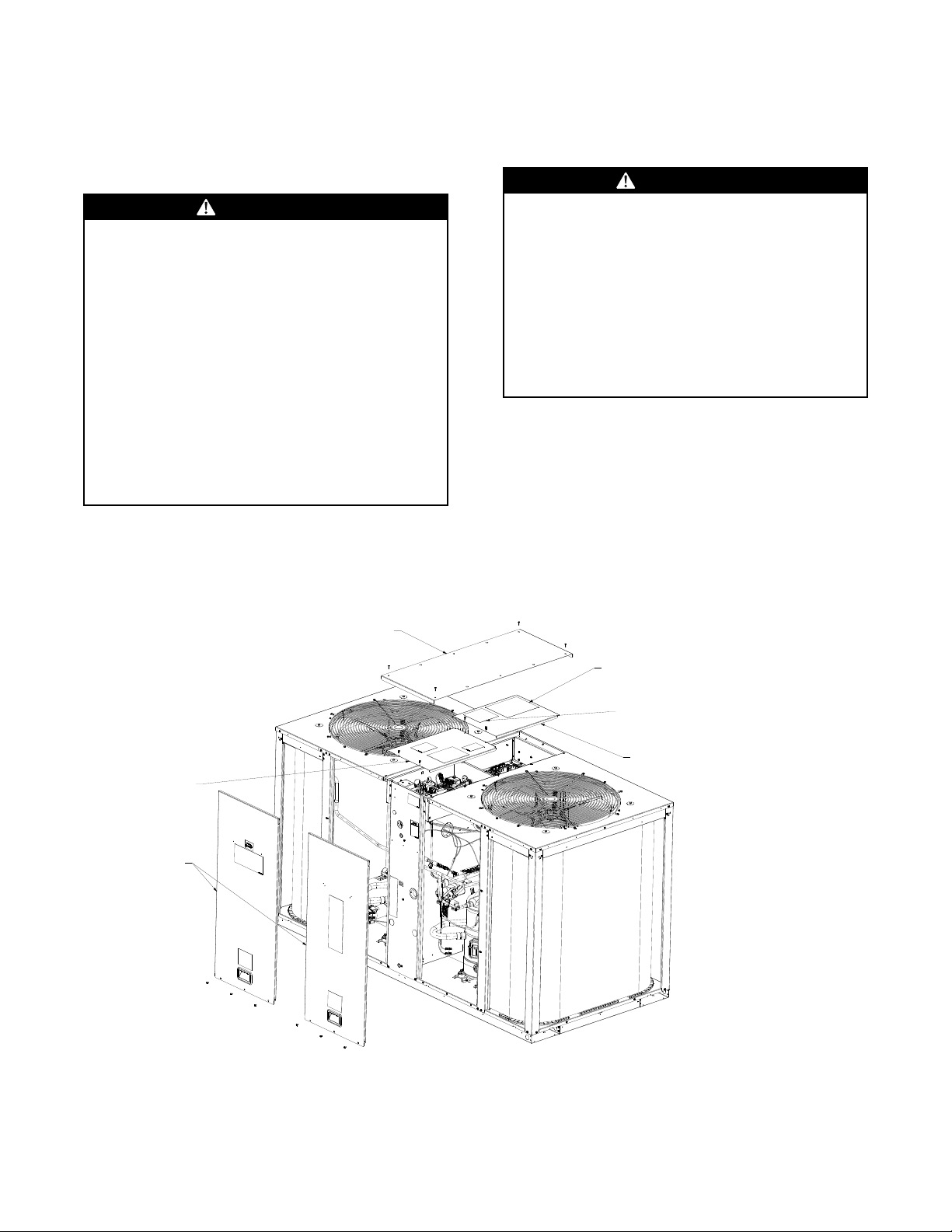
1 Prepare the unit for installation
a Disconnect and lock out all power from the unit
b Remove the compressor and control box access
panel(s), see Figure 2, p 7
2 Remove the Plug screws and install the two
brackets with edge protection as shown in Figure
3, p 8 and Figure 5, p 8
3 Mount one controller on each bracket using two 8-
32 x 1 25 screws provided Refer to Figure 4, p 8
Figure 2. Removing the compressor and control box access panel
Compressor
access panel
High voltage
control box cover
Low voltage
control box cover
Top cover
control box
Low ambient control
wiring diagram placement
Expansion control
wiring diagram placement


ACC-SVN190B-EN 9
Transducer and Tee
WWAARRNNIINNGG
RR--441100AA RReeffrriiggeerraanntt uunnddeerr HHiigghheerr
PPrreessssuurree tthhaann RR--2222!!
FFaaiilluurree ttoo uussee pprrooppeerr eeqquuiippmmeenntt oorr ccoommppoonneennttss aass
ddeessccrriibbeedd bbeellooww,, ccoouulldd rreessuulltt iinn eeqquuiippmmeenntt ffaaiilliinngg
aanndd ppoossssiibbllyy eexxppllooddiinngg,, wwhhiicchh ccoouulldd rreessuulltt iinn
ddeeaatthh,, sseerriioouuss iinnjjuurryy,, oorr eeqquuiippmmeenntt ddaammaaggee
TThhee uunniittss ddeessccrriibbeedd iinn tthhiiss mmaannuuaall uussee RR--441100AA
rreeffrriiggeerraanntt wwhhiicchh ooppeerraatteess aatt hhiigghheerr pprreessssuurreess
tthhaann RR--2222 UUssee OONNLLYY RR--441100AA rraatteedd sseerrvviiccee
eeqquuiippmmeenntt oorr ccoommppoonneennttss wwiitthh tthheessee uunniittss FFoorr
ssppeecciiffiicc hhaannddlliinngg ccoonncceerrnnss wwiitthh RR--441100AA,, pplleeaassee
ccoonnttaacctt yyoouurr llooccaall TTrraannee rreepprreesseennttaattiivvee
NNOOTTIICCEE
WWiirree DDaammaaggee!!
FFaaiilluurree ttoo ffoollllooww iinnssttrruuccttiioonnss bbeellooww ccoouulldd rreessuulltt iinn
ddaammaaggeedd wwiirreess
UUssee pprroovviiddeedd wwiirree ttiieess ttoo mmaakkee ssuurree wwiirree aarree
sseeccuurreedd aanndd pprrootteecctteedd ffrroomm sshhaarrpp eeddggeess aanndd hhoott
ssuurrffaacceess
Install a tee and pressure transducer on the discharge
line service port at each compressor using the
following instructions:
1 Remove cap nut from the unit's high pressure
service port on the discharge line that runs from the
compressor
Figure 6. High pressure service port
High pressure
service port
2 Install the transducer onto the Tee port without the
valve core
Figure 7. Transducer to tee
3 Place the Tee flare nut with valve core depressor on
the unit high pressure tap, where the cap nut was
located
NNoottee:: If the high pressure service port is on another
Tee, refer to Figure 8, p. 9 for connection.
Figure 8. Tee and transducer installed on high
pressure service port
4 Tighten flare nut securely to the high pressure
service port and check for leaks
Wiring
NNOOTTIICCEE
WWiirree DDaammaaggee!!
FFaaiilluurree ttoo ffoollllooww iinnssttrruuccttiioonnss bbeellooww ccoouulldd rreessuulltt iinn
ddaammaaggeedd wwiirreess
UUssee pprroovviiddeedd wwiirree ttiieess ttoo mmaakkee ssuurree wwiirree aarree
sseeccuurreedd aanndd pprrootteecctteedd ffrroomm sshhaarrpp eeddggeess aanndd hhoott
ssuurrffaacceess
Control Box Wiring
WWAARRNNIINNGG
HHaazzaarrddoouuss VVoollttaaggee ww//CCaappaacciittoorrss!!
FFaaiilluurree ttoo ddiissccoonnnneecctt ppoowweerr aanndd ddiisscchhaarrggee
ccaappaacciittoorrss bbeeffoorree sseerrvviicciinngg ccoouulldd rreessuulltt iinn ddeeaatthh oorr
sseerriioouuss iinnjjuurryy
DDiissccoonnnneecctt aallll eelleeccttrriicc ppoowweerr,, iinncclluuddiinngg rreemmoottee
ddiissccoonnnneeccttss aanndd ddiisscchhaarrggee aallll mmoottoorr ssttaarrtt//rruunn
ccaappaacciittoorrss bbeeffoorree sseerrvviicciinngg FFoollllooww pprrooppeerr
lloocckkoouutt//ttaaggoouutt pprroocceedduurreess ttoo eennssuurree tthhee ppoowweerr
ccaannnnoott bbee iinnaaddvveerrtteennttllyy eenneerrggiizzeedd FFoorr vvaarriiaabbllee
ffrreeqquueennccyy ddrriivveess oorr ootthheerr eenneerrggyy ssttoorriinngg
ccoommppoonneennttss pprroovviiddeedd bbyy TTrraannee oorr ootthheerrss,, rreeffeerr ttoo
tthhee aapppprroopprriiaattee mmaannuuffaaccttuurreerr’’ss lliitteerraattuurree ffoorr
aalllloowwaabbllee wwaaiittiinngg ppeerriiooddss ffoorr ddiisscchhaarrggee ooff
ccaappaacciittoorrss VVeerriiffyy wwiitthh aa CCAATT IIIIII oorr IIVV vvoollttmmeetteerr
rraatteedd ppeerr NNFFPPAA 7700EE tthhaatt aallll ccaappaacciittoorrss hhaavvee
ddiisscchhaarrggeedd
IInnssttaallllaattiioonn

10 ACC-SVN190B-EN
WWAARRNNIINNGG
PPrrooppeerr FFiieelldd WWiirriinngg aanndd GGrroouunnddiinngg
RReeqquuiirreedd!!
FFaaiilluurree ttoo ffoollllooww ccooddee ccoouulldd rreessuulltt iinn ddeeaatthh oorr
sseerriioouuss iinnjjuurryy
AAllll ffiieelldd wwiirriinngg MMUUSSTT bbee ppeerrffoorrmmeedd bbyy qquuaalliiffiieedd
ppeerrssoonnnneell IImmpprrooppeerrllyy iinnssttaalllleedd aanndd ggrroouunnddeedd
ffiieelldd wwiirriinngg ppoosseess FFIIRREE aanndd EELLEECCTTRROOCCUUTTIIOONN
hhaazzaarrddss TToo aavvooiidd tthheessee hhaazzaarrddss,, yyoouu MMUUSSTT ffoollllooww
rreeqquuiirreemmeennttss ffoorr ffiieelldd wwiirriinngg iinnssttaallllaattiioonn aanndd
ggrroouunnddiinngg aass ddeessccrriibbeedd iinn NNEECC aanndd yyoouurr llooccaall//
ssttaattee//nnaattiioonnaall eelleeccttrriiccaall ccooddeess
1 Ensure Unit power has been disconnected and
locked out
2 Disconnect both fan motor harnesses from
contactors, install 14 gauge wire harnesses
(supplied in kit) between the controller, fan
contactors and outdoor fan motor harnesses for
both refrigeration circuits See Figure 9, p 11
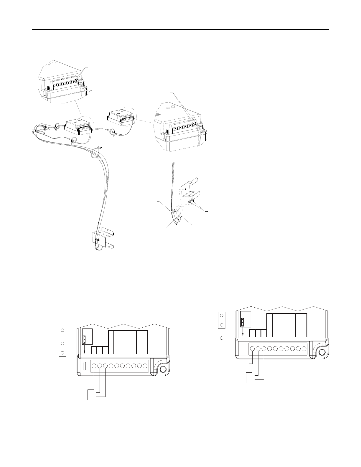
3 FOR HEAT PUMP UNITS ONLY, connect Switchover
valve 1 (SOV1) harness (supplied in kit) using the
following steps:
a Disconnect black wire from SOV1 See Figure
10, p 12
b Reconnect black wire to black wire in kit harness
by making an in-line connection Securely
attach this in-line connection to adjacent wiring
with wire ties See Figure 11, p 12
c Connect terminal with black and orange wires to
the open tab on SOV1 See Figure 11, p 12
d Connect orange wire with stripped end to Rev
valve terminal on low amb controller 1 See
Figure 11, p 12
4 FOR HEAT PUMP UNITS ONLY, connect Switchover
valve 2 (SOV2) harness (supplied in kit) using the
following steps:
a Disconnect blue wire from SOV2 See Figure
10, p 12
b Reconnect blue wire to black wire in kit harness
by making an in-line connection Securely
attach this in-line connection to adjacent wiring
with wire ties See Figure 11, p 12
c Connect terminal with black and orange wires to
the open tab on SOV2 See Figure 11, p 12
d Connect orange wire with strip end to Rev valve
terminal on low amb controller 2 See Figure
11, p 12
5 Install jumper harness (supplied in kit) between the
two controllers See diagram for reference See
Figure 12, p 13
6 Install 24VAC harness (supplied in kit) between unit
controller (UC-P5) and the Low Ambient
Controller1 See Figure 13, p 13
7 For each refrigeration circuit install transducer
wires to controller as per kit diagram See Figure
14, p 14
8 For each refrigeration circuit install the thermistors
on the outdoor air sensor bracket and connect on
controller as per kit diagram See Figure 15, p 15
9 Finish wiring installation
a Using wire ties, bundle and dress any excess
wires away from sharp edges, moving parts, or
hot tubes
b Apply the diagram (supplied in kit) to an open
area on the low voltage access panel See
Figure 2, p 7 for proper replacement
c After the settings have been properly adjusted
(see ““Controller Settings,” p 15), reinstall the
compressor and control box access panels and
secure with screws that were removed
IInnssttaallllaattiioonn


ACC-SVN190B-EN 15
Figure 15. Thermistor wires
Thermistor #2
Low Ambient
Controller
Pop-in Wire Tie
Thermistor #1
Low Ambient
Controller
Grommets
To Thermistor #1
To Thermistor #2
Controller Settings
Jumper Position for TTA Models (Cooling
Only)
For non-heat pump applications, the heat pump select
jumper must be in the Default (N O ) position, and the
HP terminals must be left unconnected Refer to Figure
16, p 15
Figure 16. Jumper position for TTA
N.C.
C
Y1
REV. VALVE
P1&P2 BLK
HEAT
PUMP
N.O.
T AMBIENT
P1&P2 RED
P2 B.W.G.
P1 B.W.G.
Y1
Y2
T’STAT
24 VAC
COMMON
Y2
N.O.
Jumper Position for TWA Models (Heat
Pump)
For heat pump applications, the heat pump select
jumper must be in the (N C ) position, see Figure 17, p
15
Figure 17. Jumper position for TWA
N.C.
C
Y1
REV. VALVE
P1&P2 BLK
HEAT
PUMP
N.O.
T AMBIENT
P1&P2 RED
P2 B.W.G.
P1 B.W.G.
Y1
Y2
T’STAT
24 VAC
COMMON
Y2
N.C.
Operation
The low ambient controller is used to maintain head
pressure within an acceptable range when ambient
temperature falls below 50 °F It reads discharge
pressure from the refrigeration circuit and “cycles” the
outdoor fan motor on and off to maintain the desired
IInnssttaallllaattiioonn
16 ACC-SVN190B-EN
discharge pressure at the selected setpoint anytime the
compressor is operating
Set Pressure Setpoint
The pressure setpoint should be adjusted to 250 psig
initially When the ambient temperature is above 50°F
(10°C), the outdoor fan motor will be energized
continuously When the ambient temperature is below
50°F, the pressure sensor reading is used to switch the
motor on or off When the pressure is 15psi below the
set pressure the motor will be turned off When the
pressure is 15psi above the set pressure, the motor will
be turned on
After completion of installation and pressure setting
adjustment), reinstall the compressor and control box
access panels and secure with screws that were
removed
Reconnect all power to the unit Refer to
troubleshooting guide, if needed
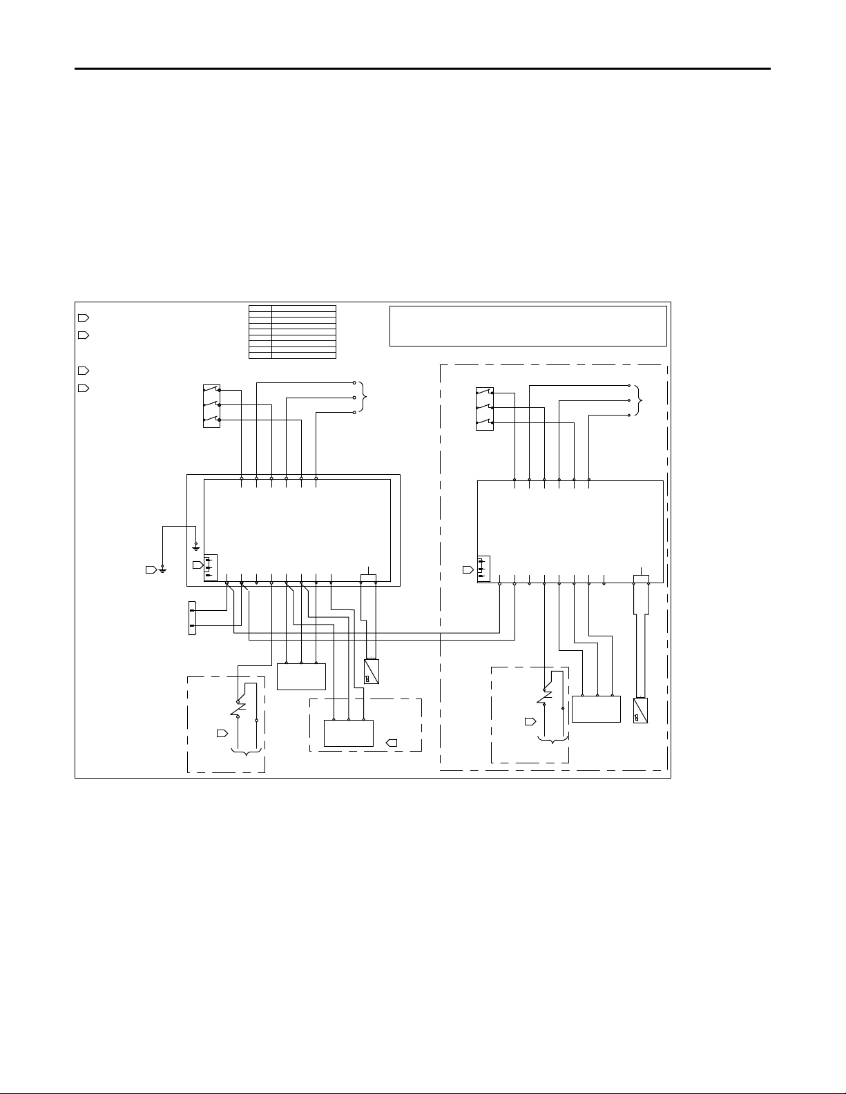
Figure 18. Supplemental wiring diagram
DEV DES DESCRIPTION
LAT1 AMBIENT TEMPERATURE 1
LAT2 AMBIENT TEMPERATURE 2
LOAM 1 LOW AMBIENT MODULE 1
LOAM 2 LOW AMBIENT MODULE 2
OFC1 OUTDOOR FAN CONTACTOR 1
OFC2 OUTDOOR FAN CONTACTOR 2
XDCR1 PRESSURE TRANSDUCER #1
XDCR2 PRESSURE TRANSDUCER #2
WHITEWHITE
RED
RED
BLACKBLACK
BROWN
BROWN
BROWN
BROWN
YELLOW
YELLOW
BROWN
BROWN
ORANGE
ORANGE
BROWN
BROWN
ORANGE
ORANGE
YELLOW
YELLOW
WHITE
WHITE
RED
RED
BLACK
BLACK
ORANGE ORANGE
BLACK
RED
BLACK
ORANGE
BLUE
BROWN
BROWN
BROWN
BROWN
WHITE
WHITE
RED
RED
BLACK
BLACK
YELLOW
YELLOW
BROWN
BROWN
ORANGE
ORANGE
BROWN
BROWN
ORANGE
ORANGE
YELLOW
YELLOW
RED
RED
BLACK, BLACK
BLACK
ORANGE
ORANGE
BLACK
RED
RED
BLACK
BLACK
GREEN
USE COPPER CONDUCTORS ONLY!
UNIT TERMINALS ARE NOT DESIGNED TO ACCEPT
OTHER TYPES OF CONDUCTORS.
FAILURE TO DO SO MAY CAUSE DAMAGE TO THE
EQUIPMENT.
CAUTION
¡UTILICE ÚNICAMENTE CONDUCTORES DE COBRE!
LAS TERMINALES DE LA UNIDAD NO ESTÁN DISEÑADAS
PARA ACEPTAR OTROS TIPOS DE CONDUCTORES.
SI NO LO HACE, PUEDE OCASIONAR DAÑO AL EQUIPO.
N'UTILISER QUE DES CONDUCTEURS EN CUIVRE!
LES BORNES DE L'UNITÉ NE SONT PAS CONÇUES
POUR RECEVOIR D'AUTRES TYPES DE CONDUCTEURS.
L'UTILISATION DE TOUT AUTRE CONDUCTEUR PEUT
ENDOMMAGER L'ÉQUIPEMENT.
PRECAUCIÓNATTENTION
LOW AMBIENT KIT FOR 2ND CIRCUIT
12133356-B
TO
OUTDOOR
FAN MOTOR
1 HARNESS
TO
OUTDOOR
FAN MOTOR
2 HARNESS
FACTORY SETTINGS:
CUT OUT SPEED - MIN
HARD START - MIN
SETPOINT - 250 PSIG
HEAT PUMP
ONLY
HEAT PUMP
ONLY
FACTORY
WIRES
FACTORY
WIRES
CONNECTIONS FOR
DUAL TRANSDUCERS
ON SINGLE MODULE
NOTES:
JUMPER DEFAULT POSITION IS ON N.O. FOR COOLING
ONLY UNITS, MOVE JUMPER TO N.C. POSITION FOR
HEAT PUMP UNITS
REMOVE BLACK FACTORY WIRE FROM SOV1, AND
BLUE FACTORY WIRE FROM SOV2. CONNECT THE
ORANGE WIRE/S FROM THE REV VALVE TERMINAL/S
TO SOV1 AND SOV2. CONNECT THE BLACK FACTORY
WIRE TO THE BLACK SUPPLIED WIRE IN LOAM1, AND THE
BLUE FACTORY WIRE TO THE BLACK SUPPLIED WIRE IN
LOAM2.
WHEN LOW AMBIENT KIT IS INSTALLED IN A SEPARATE
ENCLOSURE THEN TERMINATE THE GREEN WIRE IN THE
ENCLOSURE AND THE MAIN CONTROL BOX
CONNECTIONS FOR DUAL CIRCUIT ON ONE
MODULE WITH SINGLE FAN ONLY.
LAT1
L3 T3
L2 T2
L1 T1
OFC1
OUT
GND
IN
XDCR1
LAT2
L3 T3
L2 T2
L1 T1
OFC2
OUT
GND
IN
XDCR2
SOV1
SOV2
3
3
1
UC-P5
1
2
LOAM 1
T AMBIENT
C
Y1
Y2
REV VALVE
P1 & P2 BLK
P1 & P2 RED
P1 B.W.G.
P2 B.W.G.
LINE 1
LOAD 1
LINE 2
LOAD 2
LINE 3
LOAD 3
N.O.
HEAT
PUMP
N.C.
LOAM 2
T AMBIENT
C
Y1
Y2
REV VALVE
P1 & P2 BLK
P1 & P2 RED
P1 B.W.G.
P2 B.W.G.
LINE 1
LOAD 1
LINE 2
LOAD 2
LINE 3
LOAD 3
N.O.
HEAT
PUMP
N.C.
OUT
GND
IN
XDCR2
1
1
2
2
2
4
4
IInnssttaallllaattiioonn

ACC-SVN190B-EN 17
Operation and Troubleshooting
Chec out Procedure
WWAARRNNIINNGG
HHaazzaarrddoouuss SSeerrvviiccee PPrroocceedduurreess!!
FFaaiilluurree ttoo ffoollllooww aallll pprreeccaauuttiioonnss iinn tthhiiss mmaannuuaall aanndd
oonn tthhee ttaaggss,, ssttiicckkeerrss,, aanndd llaabbeellss ccoouulldd rreessuulltt iinn
ddeeaatthh oorr sseerriioouuss iinnjjuurryy
TTeecchhnniicciiaannss,, iinn oorrddeerr ttoo pprrootteecctt tthheemmsseellvveess ffrroomm
ppootteennttiiaall eelleeccttrriiccaall,, mmeecchhaanniiccaall,, aanndd cchheemmiiccaall
hhaazzaarrddss,, MMUUSSTT ffoollllooww pprreeccaauuttiioonnss iinn tthhiiss mmaannuuaall
aanndd oonn tthhee ttaaggss,, ssttiicckkeerrss,, aanndd llaabbeellss,, aass wweellll aass tthhee
ffoolllloowwiinngg iinnssttrruuccttiioonnss:: UUnnlleessss ssppeecciiffiieedd ootthheerrwwiissee,,
ddiissccoonnnneecctt aallll eelleeccttrriiccaall ppoowweerr iinncclluuddiinngg rreemmoottee
ddiissccoonnnneecctt aanndd ddiisscchhaarrggee aallll eenneerrggyy ssttoorriinngg
ddeevviicceess ssuucchh aass ccaappaacciittoorrss bbeeffoorree sseerrvviicciinngg
FFoollllooww pprrooppeerr lloocckkoouutt//ttaaggoouutt pprroocceedduurreess ttoo
eennssuurree tthhee ppoowweerr ccaann nnoott bbee iinnaaddvveerrtteennttllyy
eenneerrggiizzeedd WWhheenn nneecceessssaarryy ttoo wwoorrkk wwiitthh lliivvee
eelleeccttrriiccaall ccoommppoonneennttss,, hhaavvee aa qquuaalliiffiieedd lliicceennsseedd
eelleeccttrriicciiaann oorr ootthheerr iinnddiivviidduuaall wwhhoo hhaass bbeeeenn
ttrraaiinneedd iinn hhaannddlliinngg lliivvee eelleeccttrriiccaall ccoommppoonneennttss
ppeerrffoorrmm tthheessee ttaasskkss
Before leaving the installation, observe for correct
operation through the desired pressure range (see
Table 3, p 18)
Table 2. Troubleshooting guide
Problem Possible Cause Possible Solution
No fan operation
No 24 volt control voltage Check for 24 Vac between Y1 or Y2 and C terminals - it should read 24 volts.
No line voltage Check voltage across brown, orange, and yellow motor leads. If no voltage is
present verify all wiring is correct.
Bad fan motor or controller If fan does not start, motor is bad and should be replaced. If motor does start,
check controller settings. If motor still fails to start, replace controller.
Improper fan operation
Heat pump jumper not
configured correctly Verify the heat pump jumper is configured correctly.
Control is not wired correctly See wiring diagrams. Ensure that the 24 Vac power supply is connected.
No fan modulation
No need to modulate the fan If pressure is equal to or greater than the head pressure control setpoint, the fan
will be operating at full speed.
No input pressure to control Check for proper transducer and Tee installation. Schrader valve depressor must
depress Schrader valve enough to allow refrigerant into pressure transducer.
Heat pump inputs wired
incorrectly into the controller Check diagram and verify heat pump inputs are properly wired into the controller.
Miswired Check that the 24 Vac signal and the transducer are wired up correctly into the
controller.
Erratic fan operation
Control is not wired correctly See wiring diagrams.
Pressure transducer problem Check for proper transducer and Tee installation. Schrader valve depressor must
depress Schrader valve enough to allow refrigerant into pressure transducer.
Dirty or blocked condenser
coil Clean condenser coil.
The high pressure
switch trips off
Improper head pressure
setpoint setting
See unit fails to start above.
Check the setpoint and reduce it if needed.
Reduced cooling
capacity at low Ambient
Evaporative Defrost Control
is active Disable EDC function in Symbio™700


ACC-SVN190B-EN 19
NNootteess

Trane and American Standard create comfortable, energy efficient indoor environments for
commercial and residential applications For more information, please visit trane com or
americanstandardair com
Trane and American Standard have a policy of continuous product and product data improvement and reserve the right to change design and
specifications without notice We are committed to using environmentally conscious print practices
ACC-SVN190B-EN 20 Aug 2021
Supersedes ACC-SVN190A-EN (March 2020) ©2021
This manual suits for next models
10
Table of contents


